1969 DATSUN B110 gas type
[x] Cancel search: gas typePage 9 of 136

aintenIDce
une
up
Find
the
cause
for
necessary
corrective
action
b
Oil
with
extremely
low
viscosity
in
dicates
dllutton
with
gasoline
Check
011
level
If
found
below
L
mark
refill
to
H
mark
on
gauge
OIL
FILTER
The
011
filter
IS
of
a
cartndge
type
Check
for
011
leaks
through
gasketed
flange
If
any
leakage
IS
found
retIghten
shghtly
If
nece
sary
replaLe
filter
as
an
assembly
When
mstalhng
an
011
filter
tIghten
by
hand
Note
Do
not
overtighten
011
fIlter
or
oil
leakage
may
result
I
I
Fig
3
Checking
engine
011
level
Oc
OF
I
0
121
20141
30
21
401401
5015BI
I
EGOQl
I
10
20
Fig
4
Protection
concentration
COOLANT
L
L
C
IS
al
ethylene
glycol
base
product
con
tammg
chemical
mhlbltors
to
protect
the
coohng
system
from
rustmg
and
corrosIOn
The
L
I
C
does
not
con
tam
any
glycerme
ethyl
or
methyl
alcohol
It
wIll
not
evaporate
or
bOll
away
and
can
be
used
wIth
either
high
or
low
temperature
thermostat
It
flows
freely
transfers
heat
effiCiently
and
will
not
clog
the
passages
m
the
coohng
system
The
L
L
C
must
not
be
mIxed
wIth
other
products
ThiS
coolant
can
be
used
throughout
the
seasons
of
the
year
Whenever
any
coolant
IS
changed
the
coohng
system
should
be
flushed
and
refilled
wIth
a
new
coolant
Check
the
level
COMPRESSION
Compression
pressure
test
Note
To
test
cylinder
compression
remove
all
spark
plugs
and
hold
tester
fit
Percent
BOllIng
pomt
concen
09
kg
cm2
Freeze
tra
lion
Sea
level
coolmg
sys
protectIon
tern
pressure
30
2210F
2550F
50f
50
2280
F
2610F
31oF
ETO
104
Fig
5
Testing
compressIon
pressure
7
Page 30 of 136

BDgiDe
Install
the
new
011
seal
to
the
front
cover
The
front
cover
011
seal
should
be
replaced
when
the
front
cover
IS
disassembled
Install
the
front
cover
applYing
the
seahng
agent
to
both
surfaces
of
the
gasket
Tlghtemng
torque
36
to
5
1
ft
lb
Install
the
ot
strainer
and
the
011
pan
uSing
the
gasket
Apply
seahng
agent
on
both
surfaces
of
the
gasket
especIally
on
the
front
and
rear
por
tlOns
of
the
011
pan
011
pan
tlghtemng
torque
2
9
to
4
3
ft
lb
Invert
the
engine
and
Install
the
cyhnder
head
assembly
and
gasket
Note
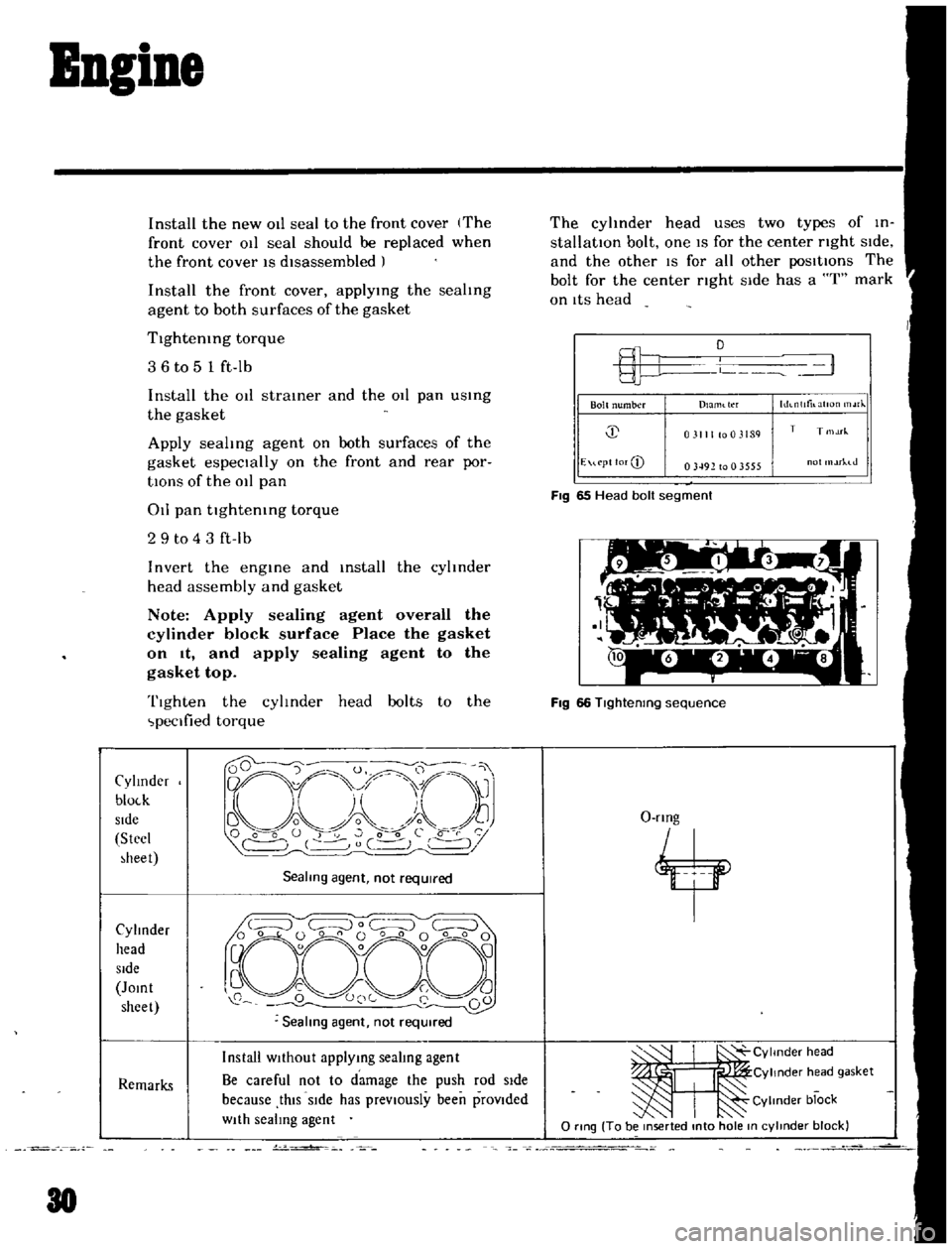
Apply
sealing
agent
overall
the
cylinder
block
surface
Place
the
gasket
on
It
and
apply
sealing
agent
to
the
gasket
top
Tighten
the
cylinder
head
bolts
to
the
peclfied
torque
Cylmder
bloLk
Side
Stecl
heet
Sealmg
agent
not
required
Cylinder
head
Side
Jomt
sheet
Remarks
Install
WIthout
applymg
sealing
agent
Be
careful
not
to
damage
the
push
rod
Side
because
thIS
SIde
has
prevIOusly
been
provIded
WIth
sealing
agent
J
30
v
o
The
cyhnder
head
uses
two
types
of
in
stallatIOn
bolt
one
IS
for
the
center
nght
SIde
and
the
other
IS
for
all
other
posItIOns
The
bolt
for
the
center
nght
Side
has
a
I
mark
on
ItS
head
L
1
Bolt
number
hh
nlltilatlOn
rJ
Dlaml
tl
f
j
031111003189
T
T
1M
E
u
pt
lor
CD
03492
to
0
3555
ot
rhJ
FIg
65
Head
bolt
segment
Fig
66
Tlghtenmg
sequence
O
rmg
4
ItI
CYlmder
head
Cylinder
h
ad
gasket
Cylinder
block
o
rtng
To
be
mserted
mto
hole
m
cylmder
block
Page 47 of 136

ruel
Sptem
FUEL
FILTER
DESCRIPTION
The
fuel
filter
IS
of
a
cartndge
type
It
uses
paper
element
as
traIner
element
which
can
be
checked
for
condItIOn
from
outsIde
ThIS
filter
cannot
be
cleaned
Replace
the
filter
at
the
peclfied
servICe
Interval
01
If
It
becomes
clogged
or
I
estncted
REMOVAL
DIsconnect
Inlet
and
outlet
fuel
hnes
from
fuel
filter
and
remove
fuel
filter
if
EF005
Fig
87
Sectional
view
of
cartridge
type
fuel
filter
Note
Before
disconnecting
fuel
lines
use
a
container
to
receive
the
remaining
fuel
In
lines
INSTALLATION
InstallatIOn
IS
the
reverse
of
removal
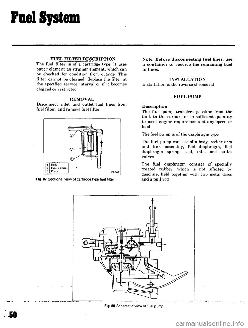
FUEL
PUMP
Description
The
fuel
pump
transfers
gasoline
from
the
tank
to
the
carburetor
In
suffiCient
quantity
to
meet
engine
requIrements
at
any
speed
or
load
The
fuel
pump
IS
of
the
diaphragm
type
The
fuel
pump
conSIsts
of
a
body
rocker
arm
and
link
assembly
fuel
diaphragm
fuel
diaphragm
spnng
seal
Inlet
and
outlet
valves
The
fuel
diaphragm
consists
of
specially
treated
rubber
whIch
IS
not
affected
by
gasohne
held
together
WIth
two
metal
diSCS
and
a
pull
rod
t
Fig
88
SchematiC
view
of
fuel
pump
R
0
Page 49 of 136

Fuel
Sptem
Capacity
Test
The
capaclty
test
IS
used
only
when
the
statIc
plessure
IS
wlthm
specIficatIOns
The
capacity
test
IS
conducted
as
follows
Disconnect
the
fuel
p1pe
at
the
carburetor
Place
a
bUltable
contamer
at
the
end
of
the
pIpe
Start
the
engme
and
run
at
1
000
rpm
The
pump
should
delIver
1
US
pt
of
fuel
In
one
mmute
or
less
If
no
gasolme
or
only
a
lIttle
flows
flOm
open
end
of
pIpe
the
fuel
pIpe
IS
clogged
or
the
pump
I
malfunctlOntng
Before
removing
the
pump
remove
the
gas
tank
cap
dIsconnect
both
Inlet
dnd
outlet
pIpes
and
blow
through
them
wIth
an
aIr
hose
to
make
sure
that
they
are
clear
Thl
wIll
elImmate
pOSSible
clogged
gas
tramer
In
the
fuel
tank
Reconnect
the
pIpes
to
the
pump
and
rete
t
flow
Removal
and
DisassenbIy
Remove
the
fuel
pump
assembly
by
un
screwmg
two
mounting
nuts
and
dIsassemble
In
the
follOWing
order
Separate
the
upper
body
and
the
lower
body
by
unscrewmg
the
body
set
screws
Take
off
the
cap
and
the
cap
gasket
by
I
emOVIng
the
cap
screw
Unscrew
the
elbow
and
the
connector
Take
off
the
valve
retainer
by
unscrewmg
two
valve
retamer
screws
Two
valves
are
eaSIly
removed
To
remove
the
diaphragm
diaphragm
sprmg
lower
body
seal
washer
and
lower
body
seal
from
the
lower
body
press
down
the
dIaphragm
counter
to
the
force
of
the
dIaphragm
spring
and
while
dOIng
thIS
cant
the
dIaphragm
so
that
the
rectangular
part
m
the
lower
end
of
the
pull
rod
IS
unhooked
from
the
rocker
arm
lInk
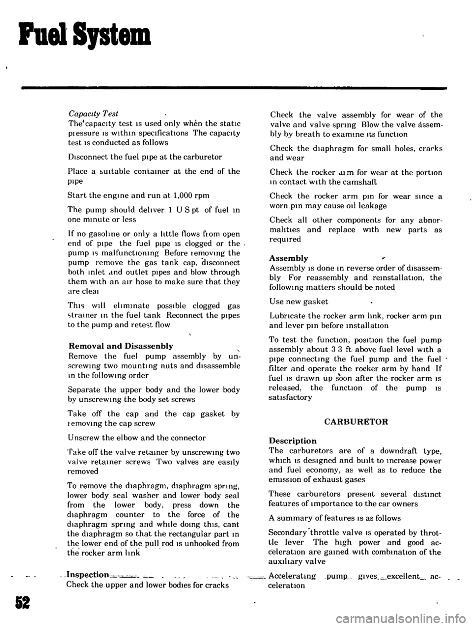
Inspection
Check
the
upper
and
lower
bodIes
for
cracks
2
Check
the
valve
assembly
for
wear
of
the
valve
and
valve
sprmg
Blow
the
valve
assem
bly
by
breath
to
examme
ItS
functIOn
Check
the
dIaphragm
for
small
holes
cral
ks
and
wear
Check
the
rocker
dl
m
for
wear
at
the
portIOn
In
contact
With
the
camshaft
Check
the
rocker
arm
pin
for
wear
since
a
worn
pm
may
cause
011
leakage
Check
all
other
components
for
any
abnor
mahtIes
and
replace
With
new
parts
as
requIred
Assembly
Assembly
IS
done
In
reverse
order
of
disassem
bly
For
reassembly
and
remstallatlOn
the
followmg
matters
should
be
noted
Use
new
gasket
Lubricate
the
rocker
arm
link
rocker
arm
pm
and
lever
pm
before
mstallatlOlI
To
test
the
functIOn
poSItIOn
the
fuel
pump
assembly
about
33ft
above
fuel
level
WIth
a
pipe
connecting
the
fuel
pump
and
the
fuel
filter
and
operate
the
rocker
arm
by
hand
If
fuel
IS
drawn
up
soon
after
the
rocker
arm
IS
released
the
functIOn
of
the
pump
IS
satIsfactory
CARBURETOR
Description
The
carburetors
are
of
a
downdraft
type
whIch
IS
deSIgned
and
bUIlt
to
Increase
power
and
fuel
economy
as
well
as
to
reduce
the
em1SSlon
of
exhaust
gases
These
carburetors
present
several
dIstinct
features
of
Importance
to
the
car
owners
A
summary
of
features
IS
as
follows
Secondary
throttle
valve
IS
operated
by
throt
tie
lever
The
hIgh
power
and
good
ac
celeratIon
are
gained
With
combmatlOn
of
the
auxlhary
valve
Acceleratmg
pump
glves
excellent
ac
celeratIon
Page 119 of 136

Specifications
RECOMMENDED
LUBRICANT
SPECI
f
ICATIONS
Item
SpeCificatiOnS
Remarks
SAE
ClaSSIfIcatIon
Furthermore
refer
to
GasolIne
engme
011
SD
or
SE
SAE
recommended
VISCOSity
table
See
Page
GI
5
Transmission
and
API
GL4
0
steenng
l
Dlfferenllal
I
API
GLS
Automallc
TIM
flUId
Type
DEXRON
MultIpurpose
grease
NLGI2
LIthIUm
soap
base
Brake
and
clutch
flUId
OOT3
Antifreeze
coolant
Long
LIfe
Coolant
130