Page 2 of 136

lI
I
DATSUN
1200
RANGE
1971
1973
MAINTENANCE
REPAIR
BY
DRAKE
AUTOMOTIVE
EDITORS
Quick
Referencelodel
MAINTENANCE
TUNE
UP
5
STEERING
89
ENGINEERING
13
REAR
DRIVE
ELECTRICAL
SYSTEM
35
SUSPENSION
93
IGNITION
SYSTEM
43
CLUTCH
99
FUEL
SYSTEM
49
TRANSMISSION
103
COOLING
SYSTEM
63
BODY
WORK
111
BRAKES
67
SPECIFICATIONS
129
FRONT
SUSPENSION
83
The
purpose
of
this
manual
IS
to
provide
the
automobile
owner
and
mechanic
with
a
reference
source
with
which
he
can
perform
normal
service
operations
We
endeavor
to
lOcorporate
the
latest
manufacturing
design
changes
and
up
to
date
specifications
at
the
time
of
publication
While
every
effort
IS
made
to
attain
accuracy
the
Publisher
cannot
be
held
responsible
for
manufacturing
changes
typographical
errors
or
omiSSions
Upon
compIling
the
information
contained
herein
we
have
tried
to
be
brief
and
Simple
relvlng
on
the
combination
of
photographs
Illustrations
and
text
to
make
thIS
manual
a
useful
tool
DRAKE
PUBLISHERS
INC
361
PARK
AVENUE
SOUTH
NEW
YORK
NY
10016
Page 4 of 136

able
of
Contents
MAINTENANCE
TUNE
UP
DIsassembly
32
InspectIOn
RepaIr
33
VALVE
CLEARANCES
6
AdJustmg
Regulator
33
ENGINE
OIL
6
Assembly
33
OIL
FILTER
7
COOLANT
7
COMPRESSION
7
ELECTRICAL
SYSTEM
BATTERY
8
IGNITION
TIMING
8
STARTER
36
DIstributor
Breaker
Pomt
9
Removal
37
Condenser
9
InstallatIOn
37
Spark
Plugs
9
Trouble
Shootmg
37
Carburetor
9
ALTERNATOR
36
Idle
LImIter
Cap
10
Removal
37
Dash
Pot
automatic
transmISSIOn
11
InstallatIOn
37
model
only
11
REGULATOR
39
Carburetor
Return
Sprmg
11
DeSCriptIOn
39
Fuel
Filter
11
Trouble
Shootmg
40
ENGINE
IGNITION
SYSTEM
DESCRIPTION
14
DISTRIBUTOR
44
REMOVAL
14
ConstructIOn
44
INSTALLATION
14
Checkmg
and
Adjustment
44
CLEANING
INSPECTION
14
SP
ARK
PLUGS
46
DISASSEMBL
Y
14
DeSCriptIOn
46
INSPECTION
REPAIR
18
InspectIOn
46
PreparatIOn
18
Cleamng
Regap
47
Cyltnder
Head
18
Valve
Assembly
18
Valve
Spnng
19
Valve
Rocker
Shaft
Rocker
Arm
19
FUEL
SYSTEM
Valve
LIfter
Push
Rod
20
Camshaft
Camshaft
Bearmg
20
FUEL
FILTER
50
Valve
Tlmmg
20
DESCRIPTION
50
Cyltnder
Block
21
REMOVAL
50
PIston
Piston
Pm
Plsto
LRmg
21
INSTALLATION
50
Connectmg
Rod
23
FUEL
PUMP
50
Crankshaft
24
DeSCriptIOn
50
Bushmg
Bearing
24
Testmg
51
Crankshaft
Sprocket
Removal
DIsassembly
52
Camshaft
Sprocket
25
InspectIOn
52
Flywheel
25
Assembly
52
ASSEMBL
Y
25
CARBURETOR
52
PrecautIOn
25
DeSCription
52
Cyltnder
Head
25
Adjustment
53
PIston
ConnectIng
Rod
26
Removal
58
Engme
26
DIsassembly
58
OIL
PUMP
32
Cleanmg
InspectIOn
59
Removal
Engme
m
vehicle
32
Assembly
InstallatIOn
60
I
Page 6 of 136
fable
of
Contents
BODY
WORK
SPECIFICATIONS
I
HOOD
112
SERVICE
DATA
130
Removal
112
ENGINE
134
InstallatIOn
112
General
SpeCificatIOn
134
HOOD
LOCK
112
Tlghtemng
Torque
134
Removal
112
SpeCIficatIOn
135
Adjustment
112
Coohng
System
139
LubncatlOn
114
Fuel
System
140
TRUNK
LID
LOCK
116
Starter
142
Removal
116
Alternator
143
Adjustment
116
Regulator
144
TRUNK
LID
TORSION
BAR
116
Dlstnbutor
145
DOOR
CONSTRUCTION
117
IgnItIOn
Cot
145
WIRING
DIAGRAMS
118
CLUTCH
146
BULB
SPECIFICATIONS
120
NOTES
174
HEADLAMP
121
THERMOMETER
AND
FUEL
METER
122
OIL
PRESSURE
AND
IGNITION
WARNING
LAMPS
126
I
I
t
I
3
Page 13 of 136
aiDtenuce
TUDe
up
Fig
12
Fuel
strainer
Install
Idle
hmlter
cap
m
posItion
makmg
sure
that
the
adJustmg
screw
can
further
turn
rotatIOn
m
the
CO
RICH
d1rectlOn
Dash
Pot
Automatic
Transmission
Model
Only
Check
operation
of
dash
pot
It
should
not
be
cracked
or
bound
It
IS
also
essenttal
to
check
r
w
be
certam
that
It
IS
m
correct
adjustment
Check
to
be
sure
that
dash
pot
contacts
stop
per
lever
when
engme
speed
reaches
1
900
to
2
000
rpm
Engme
should
be
slowed
down
from
3
000
to
1
000
rpm
within
a
few
seconds
Readjust
dash
pot
or
replace
It
with
a
new
one
lflt
falls
to
meet
the
above
condItions
Carburetor
Return
Spring
Check
throttle
return
sprmg
for
sign
of
damage
wear
or
squareness
Discard
spring
If
found
wIth
any
of
above
excessIvely
beyond
use
Fuel
Filter
Check
for
a
contammatlOn
element
water
depoSIt
and
defection
All
engmes
use
a
cartridge
type
strainer
If
1t
IS
found
to
be
defective
replace
as
an
assembly
u
Page 14 of 136
IQgiDe
DESCRIPTION
The
A12
engme
IS
a
715
cu
m
In
I
me
over
head
valve
four
cyltnder
engine
with
2874
m
bore
and
2
765
m
stroke
It
feature
full
opened
wedge
shaped
combustIOn
cham
ber
alummum
heads
and
fully
balanced
5
bearmg
crankshaft
to
turn
out
smooth
dependable
power
REMOVAL
Removmg
hood
Open
the
hood
remove
four
mstallatlOn
bolts
and
remove
the
hood
Disconnect
the
battery
cable
from
the
ter
mmal
Removmg
radIator
Dram
water
from
the
radiator
disconnect
two
radIator
hoses
remove
four
radIator
m
stallatlOn
bolts
and
remove
the
radiator
Removmg
cables
and
hoses
Disconnect
the
followmg
cables
hoses
and
wires
High
voltage
cable
between
Igmtton
COlI
and
distributor
Cable
to
the
thermal
transmitter
Cable
to
the
011
pressure
sW1tch
Cable
to
the
primary
Side
of
the
distributor
Cable
to
the
startmg
motor
Fuel
hose
Cable
to
the
alternator
Heater
hose
for
model
With
heater
only
I
Fig
13
Sectional
view
of
A
12
Engine
It
Page 16 of 136
Bngine
Remove
the
altel
nator
and
engine
mounting
bracket
L
H
slde
Remove
the
crankshaft
pulley
Remove
the
011
pump
together
With
the
011
filtel
Remove
the
high
tensIOn
cable
wIth
the
dlstnbutor
cap
on
Remove
the
spark
plugs
Remove
the
dlstllbutor
assembly
Remove
the
carburetor
Remove
the
rocker
cover
Remove
the
thermo
itat
houslllg
Remove
the
manifolds
Remove
the
water
pump
Remove
the
fuel
pump
Fig
16
Manifolds
removal
Fig
17
Water
pump
removal
18
Remove
the
rocker
shaft
assembly
and
push
rods
Remove
the
cylInder
head
assembly
Invert
the
engine
Fig
18
Rocker
shaft
assembly
removal
7
1
l
I
h
Y
r
I
w
L
1
Fig
19
Cylinder
head
bolts
removal
sequence
o
Fig
20
011
strainer
removal
j
Page 31 of 136

BDgiDe
TIghtening
torque
40
to
43
ft
Ib
Install
the
push
rod
Install
the
rocker
haft
assembly
and
tighten
the
I
ocker
haft
bracket
bolts
to
the
specIfied
torque
Tightening
torque
15
to
18
ft
lb
Note
TIghtening
operation
should
be
made
gradually
10
separating
two
or
three
stages
and
outwardly
from
the
center
bracket
In
tall
the
Intake
and
exhaust
mamfolds
TIghtening
torque
65
to
10
ft
lb
AdJu
t
valve
clemance
wIth
the
specIfied
dlmenblOn
Install
the
rocker
cover
and
carburetor
assem
bly
I
n
tdll
the
watel
pump
and
thermostat
Tlghtemng
tOl
que
65
to
10
ft
lb
I
nstall
the
crankshaft
pulley
Tighten
the
crank
pulley
bolt
to
the
specIfied
torque
TIghtenIng
torque
109
to
116
ft
lb
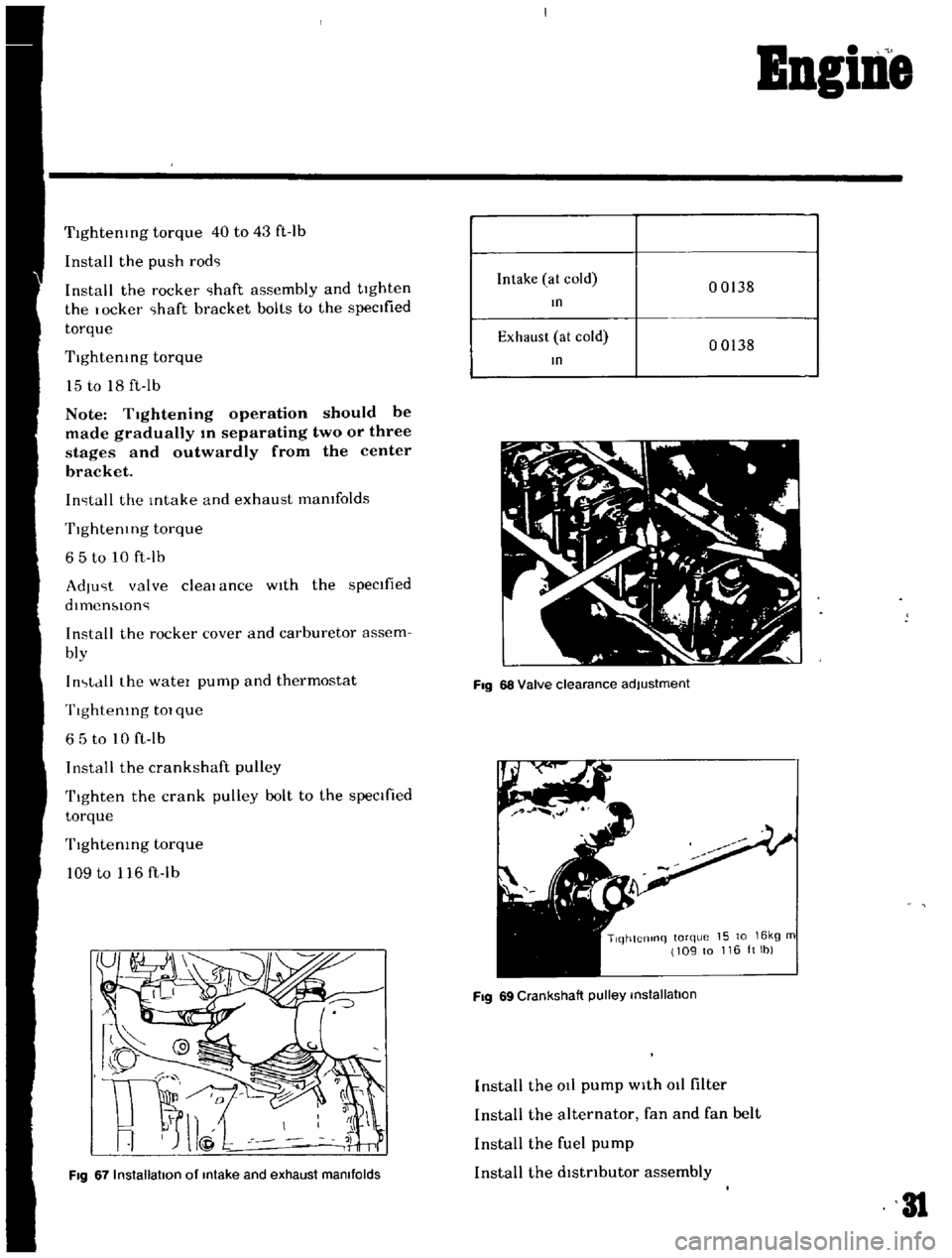
Fig
67
Installation
of
Intake
and
exhaust
manifolds
Intake
at
cold
00138
In
Exhaust
at
cold
00138
In
Fig
68
Valve
clearance
adjustment
TlqhtCnlnq
torque
15
to
16kg
m
109
to
116ltlb
Fig
69
Crankshaft
pulley
installation
Install
the
at
pump
with
011
filter
Install
the
alternator
fan
and
fan
belt
Install
the
fuel
pump
Install
the
dlstnbutor
assembly
31
Page 32 of 136

BBgiBe
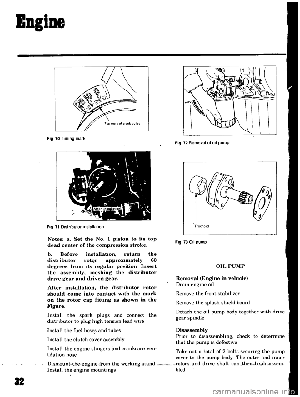
Fig
70
Tlmmg
mark
Fig
71
Dlstnbutor
mstallatlon
Notes
a
Set
the
No
1
piston
to
its
top
dead
center
of
the
compression
stroke
b
Before
installation
return
the
distributor
rotqr
approximately
60
degrees
from
Its
regular
position
Insert
the
assembly
meshing
the
distributor
drive
gear
and
driven
gear
After
installation
the
distributor
rotor
should
come
into
contact
wIth
the
mark
on
the
rotor
cap
fittmg
as
shown
in
the
Figure
Install
the
spark
plugs
and
connect
the
distrIbutor
to
plug
high
tensIOn
lead
wire
Install
the
fuel
hoses
and
tubes
Install
the
clutch
cover
assembly
Install
the
engme
shngers
and
crankcase
ven
tilatIOn
hose
Fig
72
Removal
of
011
pump
TrochoId
Fig
73011
pump
OIL
PUMP
Removal
Engine
in
vehlCIe
Dram
engme
OIl
Remove
the
front
stabilIzer
Remove
the
splash
shield
board
Detach
the
011
pump
body
together
with
drIve
gear
spmdle
Disassembly
PrIor
to
dlsassembhng
check
to
determme
that
the
pump
IS
defective
Take
out
a
total
of
2
bolts
securmg
the
pump
cover
to
the
pump
body
The
outer
and
mner
Dlsmount
the
engme
from
the
workmg
stand
rotors
and
drive
shaft
can
then
be
dlsassem
Install
the
engme
mountmgs
bled
32