1969 DATSUN B110 tow
[x] Cancel search: towPage 15 of 136
Bngine
WIres
for
accelerator
and
choke
The
operatIOn
Will
be
carned
out
more
easily
by
removing
the
a1r
cleaner
Lift
up
the
engine
toward
the
front
INST
ALLA
TION
Install
the
engine
In
reverse
sequence
of
removal
Disconnecting
clutch
wire
on
nght
hand
dnve
model
On
left
hand
dnve
model
disconnect
hydraulIc
line
from
the
clutch
slave
cylInder
DIsconnect
the
clutch
WIre
at
the
JXlrtlOn
of
the
wIthdrawal
lever
Remove
the
exhaust
front
tube
Disconnect
the
the
cable
to
the
back
up
lamp
SWItch
D1sconnect
the
speedometer
cable
Remove
the
propeller
shaft
Remove
four
bolts
used
In
the
differential
carner
SIde
and
Withdraw
the
propeller
shaft
Remove
the
shift
lever
Model
With
remote
control
shIft
lever
Disconnect
the
remote
control
rod
at
the
JXlr
tlOn
of
transmiSSIOn
outer
lever
and
remove
the
remote
control
rod
Model
With
floor
Sh1ft
lever
Remove
the
boot
WIthdraw
the
lock
pin
and
remove
the
lever
The
operatIOn
IS
carned
out
In
the
passenger
compartment
Model
With
automatic
transmiSSIOn
Remove
pinS
from
both
ends
of
the
cross
shaft
and
remove
the
shIft
rod
Suspend
the
engine
With
wire
Remove
the
front
engine
mounting
installation
nuts
Remove
the
rear
engine
mounting
installation
nuts
When
removing
the
engine
mounting
in
stallation
nuts
be
sure
to
apply
a
Jack
beneath
the
transmiSSIOn
CLEANING
AND
INSPECTION
Clean
the
engine
thoroughly
before
disassem
bly
Before
cleaning
the
engine
remove
the
l
electncal
parts
and
plug
up
the
carburetor
air
horn
to
aVOid
intrusIOn
of
foreign
matter
The
engine
extenor
Check
the
covers
and
bolts
for
breakage
rust
damage
and
loss
CylInder
block
Check
thoroughly
the
water
Jacket
for
cracks
and
breakage
Clutch
hOUSing
Check
for
cracks
011
pan
Check
for
excessive
rust
DISASSEMBLY
Mount
engine
assembly
on
engine
stand
Remove
the
engine
mounting
bracket
R
H
Side
Install
the
engine
attachment
Mount
the
engine
on
the
stand
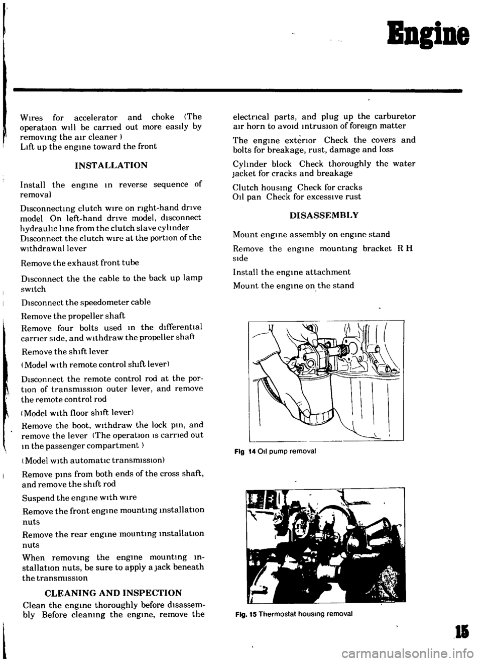
Fig
14011
pump
removal
Fig
15
Thermostat
hOUSing
removal
II
Page 26 of 136
BDgiDe
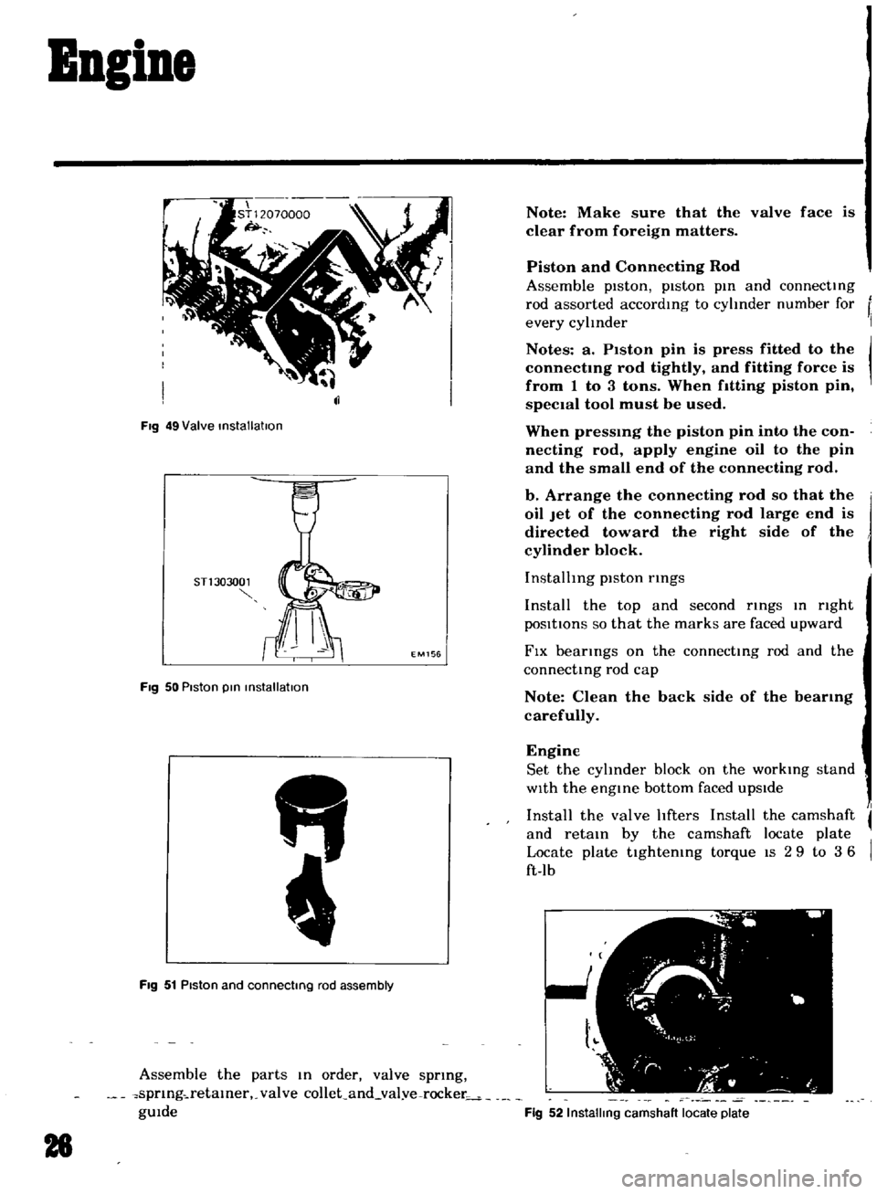
Fig
49
Valve
installatIon
STl
303001
EM156
Fig
50
Piston
pin
installation
FIg
51
Piston
and
connecting
rod
assembly
Assemble
the
parts
In
order
valve
sprmg
spnng
retamer
valve
collet
and
val
ve
rocker
gUIde
28
Note
Make
sure
that
the
valve
face
is
clear
from
foreign
matters
Piston
and
Connecting
Rod
Assemble
pIston
piston
pm
and
connecting
rod
assorted
accordmg
to
cyhnder
number
for
every
cylInder
Notes
a
P1ston
pin
is
press
fitted
to
the
connectmg
rod
tightly
and
fitting
force
is
from
1
to
3
tons
When
fitting
piston
pin
speCIal
tool
must
be
used
When
pressmg
the
piston
pin
into
the
con
necting
rod
apply
engine
oil
to
the
pin
and
the
small
end
of
the
connecting
rod
b
Arrange
the
connecting
rod
so
that
the
oil
Jet
of
the
connecting
rod
large
end
is
directed
toward
the
right
side
of
the
cylinder
block
InstallIng
piston
rmgs
Install
the
top
and
second
rings
In
nght
pOSItIOns
so
that
the
marks
are
faced
upward
FIX
bearings
on
the
connecting
rod
and
the
connecting
rod
cap
Note
Clean
the
back
side
of
the
bearmg
carefully
Engine
Set
the
cyhnder
block
on
the
workmg
stand
WIth
the
engine
bottom
faced
upSIde
Install
the
valve
hfters
Install
the
camshaft
and
retain
by
the
camshaft
locate
plate
Locate
plate
tightemng
torque
IS
2
9
to
3
6
ft
lb
Fig
52
Installing
camshaft
locate
plate
Page 27 of 136
Bogine
Note
Set
the
locate
plate
so
as
the
LOWER
mark
comes
to
the
engine
bot
tom
side
Set
the
maIn
bearIngR
on
theIr
posItIOns
on
the
cylinder
block
Notes
a
The
center
bearmg
No
3
bearmg
is
a
flanged
type
for
thrust
force
b
Two
lOner
bearmgs
No
2
and
No
4
are
of
the
same
type
c
The
front
bearmg
No
1
IS
the
same
type
as
the
rear
bearmg
No
5
d
All
bearings
except
for
No
I
bearing
are
interchangeable
between
upper
and
lower
bearings
Apply
engIne
OIl
to
the
mam
bearIng
surfaces
on
both
sIdes
of
the
cyltnder
block
and
cap
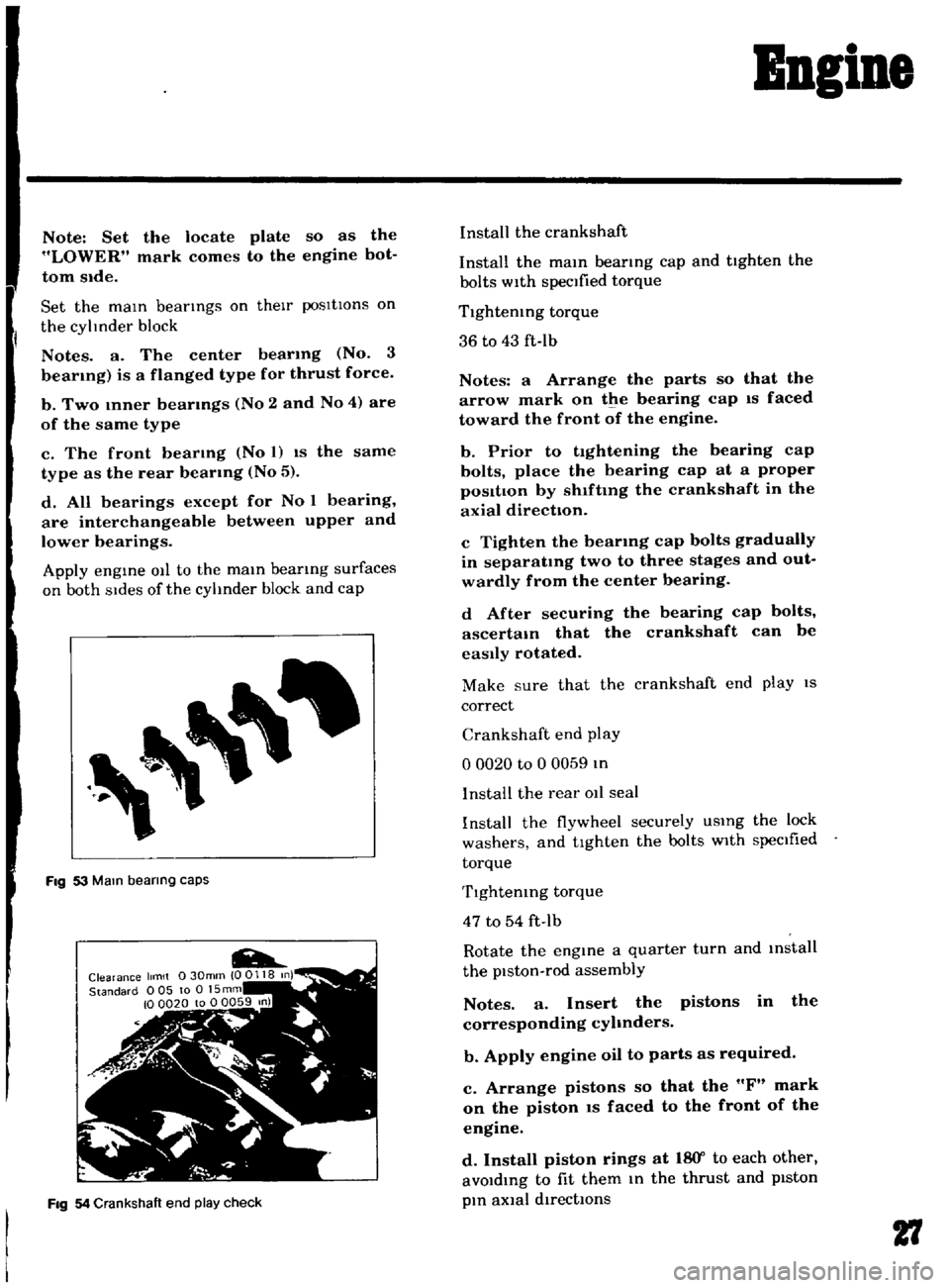
Fig
53
Mam
bearing
caps
Fig
54
Crankshaft
end
play
check
Install
the
crankshaft
Install
the
mam
bearmg
cap
and
tighten
the
bolts
with
specified
torque
Tlghtemng
torque
36
to
43
ft
Ib
Notes
a
Arrange
the
parts
so
that
the
arrow
mark
on
the
bearing
cap
IS
faced
toward
the
front
of
the
engine
b
Prior
to
tightening
the
bearing
cap
bolts
place
the
bearing
cap
at
a
proper
posItIon
by
shlftmg
the
crankshaft
in
the
axial
direction
c
Tighten
the
bearmg
cap
bolts
gradually
in
separatmg
two
to
three
stages
and
out
wardly
from
the
center
bearing
d
After
securing
the
bearing
cap
bolts
ascertam
that
the
crankshaft
can
be
easily
rotated
Make
sure
that
the
crankshaft
end
play
IS
correct
Crankshaft
end
play
o
0020
to
0
0059
In
I
nstalI
the
rear
011
seal
Install
the
flywheel
securely
USIng
the
lock
washers
and
tighten
the
bolts
with
specIfied
torque
Tlghtemng
torque
47
to
54
ft
Ib
Rotate
the
engine
a
quarter
turn
and
mstall
the
piston
rod
assembly
Notes
a
Insert
the
pistons
in
the
corresponding
cyhnders
b
Apply
engine
oil
to
parts
as
required
c
Arrange
pistons
so
that
the
F
mark
on
the
piston
IS
faced
to
the
front
of
the
engine
d
Install
piston
rings
at
18
Y
to
each
other
avoIdIng
to
fit
them
In
the
thrust
and
pIston
pIn
aXial
directIOns
27
Page 28 of 136
Bagine
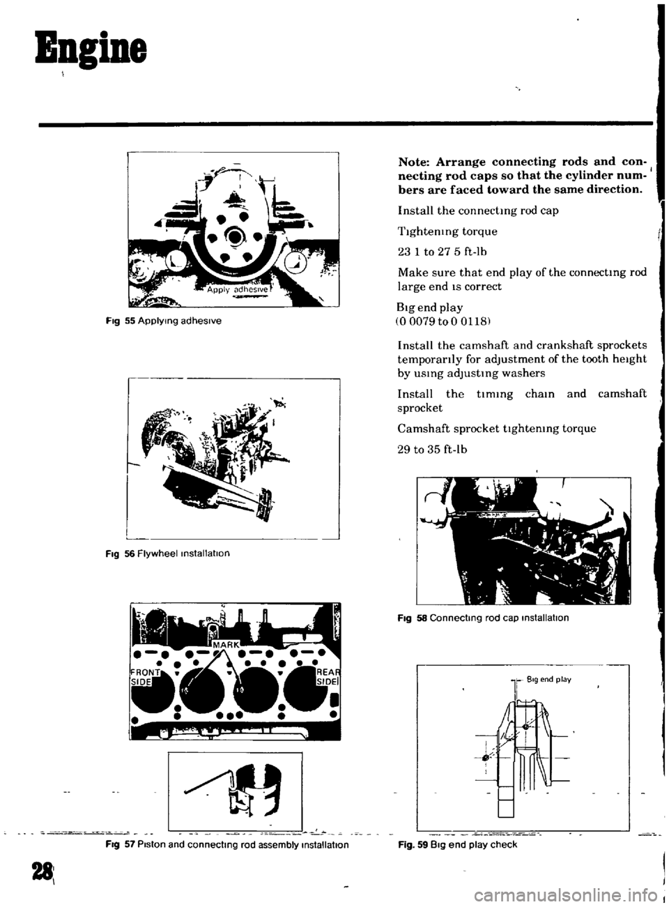
Fig
55
ApplYing
adhesive
L
FIg
56
Flywheel
installation
c
0
FIg
57
Piston
and
connecting
rod
assembly
installation
281
Note
Arrange
connecting
rods
and
con
necting
rod
caps
so
that
the
cylinder
num
bers
are
faced
toward
the
same
direction
Install
the
connectmg
rod
cap
Tlghtenmg
torque
23
1
to
27
5
ft
lb
Make
sure
that
end
play
of
the
connectmg
rod
large
end
IS
correct
Big
end
play
00079
to
0
0118
Install
the
camshaft
and
crankshaft
sprockets
temporarily
for
adjustment
of
the
tooth
height
by
usmg
adJustmg
washers
Install
the
tlmmg
cham
and
camshaft
sprocket
Camshaft
sprocket
tlghtemng
torque
29
to
35
ft
lb
FIg
58
Connecting
rod
cap
installation
Fig
59
Big
end
play
check
Page 71 of 136
Brakes
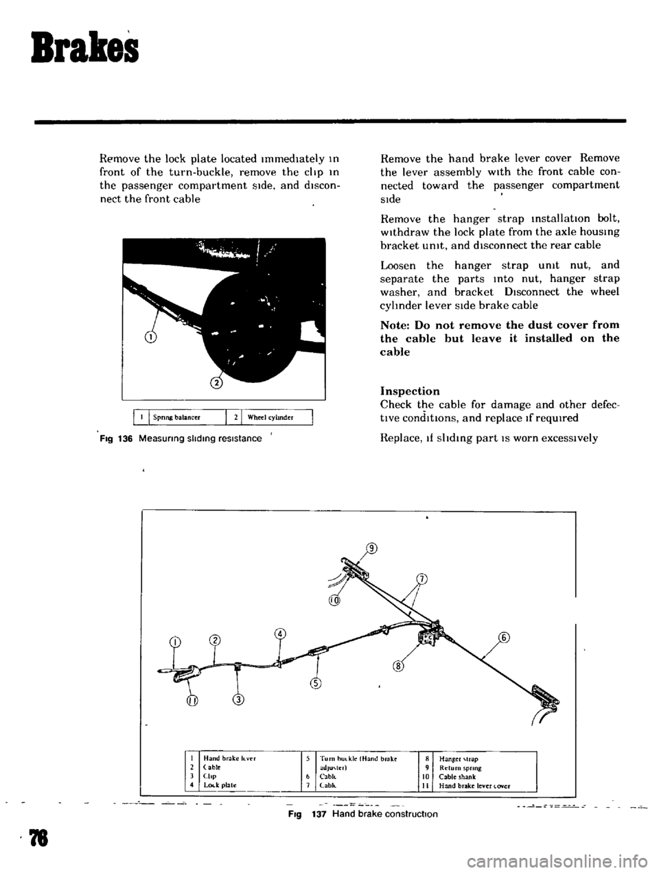
Remove
the
lock
plate
located
Immediately
III
front
of
the
turn
buckle
remove
the
clip
III
the
passenger
compartment
SIde
and
discon
nect
the
front
cable
I
Spong
balancer
G
Wheel
cyhnder
FIg
136
Measunng
slidIng
resistance
Remove
the
hand
brake
lever
cover
Remove
the
lever
assembly
wIth
the
front
cable
con
nected
toward
the
passenger
compartment
SIde
Remove
the
hanger
strap
installatIOn
bolt
withdraw
the
lock
plate
from
the
axle
hOUSIng
bracket
umt
and
disconnect
the
rear
cable
Loosen
the
hanger
strap
umt
nut
and
separate
the
parts
Into
nut
hanger
strap
washer
and
bracket
DIsconnect
the
wheel
cylinder
lever
SIde
brake
cable
Note
Do
not
remove
the
dust
cover
from
the
cable
but
leave
it
installed
on
the
cable
Inspection
Check
the
cable
for
damage
and
other
defec
tlve
condlttons
and
replace
If
reqUIred
Replace
If
shdIng
part
IS
worn
excessively
1
Hand
brake
It
ver
2
able
J
Clip
4
Lock
plate
5
Turn
hUlkle
Hand
brake
adJU
h
r
6
CabJc
7
abk
8
Han
er
trap
9
Return
sprmg
10
Cable
shank
II
Hand
brake
lever
lover
FIg
137
Hand
brake
construction
78
Page 78 of 136
pront
Suspension
Qj
@
@
I
Strut
mounting
Insulator
2
Strut
mounllng
bearing
3
Upper
pnng
o
r
at
4
Oumpu
rubblf
5
DU
tlOVU
6
P
ton
rod
7
F
ool
pring
8
Irut
embly
q
Hub
b
t
mbly
10
5pmdh
II
Ball
JOint
12
Trd
nwu
link
1
J
Tln
lon
rod
14
StJblluLr
15
SU
p
mIOn
mlmbt
r
Fig
146
Front
axle
and
suspension
assembly
I
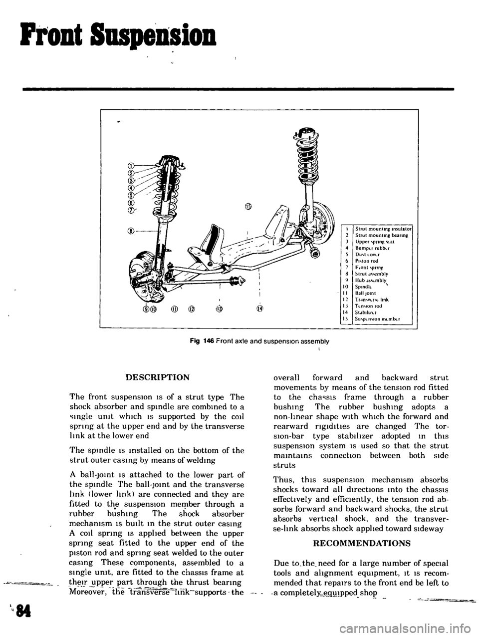
DESCRIPTION
The
front
suspensIOn
IS
of
a
strut
type
The
shock
absorber
and
spIndle
are
combIned
to
a
Ingle
Unit
whIch
IS
supported
by
the
COIl
spnng
at
the
upper
end
and
by
the
transverse
lInk
at
the
lower
end
The
spIndle
IS
Installed
on
the
bottom
of
the
strut
outer
caSIng
by
means
of
weldIng
A
ball
JOInt
IS
attached
to
the
lower
part
of
the
spIndle
The
ball
JOInt
and
the
transverse
lInk
lower
lInk
are
connected
and
they
are
fitted
to
the
suspensIOn
member
through
a
rubber
b
shIng
The
shock
absorber
mechanism
IS
bUIlt
In
the
strut
outer
caSIng
A
COIl
sprIng
IS
apphed
between
the
upper
sprIng
seat
fitted
to
the
upper
end
of
the
piston
rod
and
spring
seat
welded
to
the
outer
caSIng
These
components
assembled
to
a
SIngle
umt
are
fitted
to
the
chaSSIS
frame
at
their
upper
part
through
the
thrust
beanng
M
eover
the
1ransverse
hnk
supports
the
84
overall
forward
and
backward
strut
movements
by
means
of
the
tensIOn
rod
fitted
to
the
cha
sls
frame
through
a
rubber
bushIng
The
rubber
bushIng
adopts
a
non
lInear
shape
WIth
whICh
the
forward
and
rearward
ngldltles
are
changed
The
tor
slOn
bar
type
stabilIzer
adopted
In
thiS
suspensIOn
system
IS
used
so
that
the
strut
maIntaInS
connectIOn
between
both
Side
struts
Thus
thiS
suspensIOn
mechanism
absorbs
shocks
toward
all
directIOns
Into
the
chaSSIS
effectively
and
effiCIently
the
tensIOn
rod
ab
sorbs
forward
and
backward
shocks
the
strut
absorbs
vertical
shock
and
the
transver
se
lInk
absorbs
shock
applIed
toward
SIdeway
RECOMMENDATIONS
Due
to
the
need
for
a
large
number
of
speCial
tools
and
ahgnment
eqUIpment
It
IS
recom
mended
that
repairs
to
the
front
end
be
left
to
a
completely
e
q
pped
shop
Page 88 of 136
Bear
Drive
Suspension
A
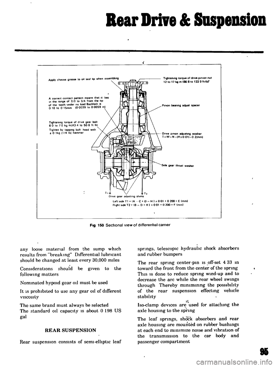
correct
contact
pattern
means
that
It
beii
the
ange
of
2
3
to
3
4
from
the
tip
of
the
tooth
nder
no
load
Backlash
IS
010
to
015mm
00039
to
00059
n
Tlghtemng
torque
of
drlve
gear
bolt
60
to
70
kg
m
434
to
506
ft
Ibl
TIghten
by
tapping
bolt
head
with
a
0
lkg
1
4
lb
hammer
TIghtening
torque
of
dnvt
pmlon
nut
12
to
11
kg
m
86
8
to
1229
ft
lb
Plmon
be
nng
adjust
spacer
O
lve
plmon
adlustlng
washer
T
W
N
HxO
011
0
2
mml
T
T
Drive
gear
ad
ustlng
shims
Left
Ide
T1
jA
C
0
H
I
001
0200
E
lmml
Right
SIde
T2
B
D
HI
001
0
200
F
mml
Fig
150
Sectional
view
of
dIfferentIal
carner
any
loose
matenal
from
the
sump
which
results
from
breaking
Dlfferentlallubncant
should
be
changed
at
least
every
30
000
m11es
ConsIderatIOns
should
be
given
to
the
follOWing
matters
Nommated
hYPOld
gear
011
must
be
used
It
IS
prohibited
to
use
any
gear
011
of
dIfferent
VISCOSity
The
same
brand
must
always
be
selected
The
standard
011
capacity
IS
about
0
198
US
gal
REAR
SUSPENSION
Rear
suspensIOn
consists
of
serm
elhptlc
leaf
springs
telescopIc
hydrauhc
shock
absorbers
and
rubber
bumpers
The
rear
sprmg
center
pm
1S
ofT
set
4
33
m
toward
the
front
from
the
center
of
the
sprmg
ThIS
IS
done
to
reduce
sprmg
wmd
up
and
to
decrease
the
arc
while
the
rear
wheel
sWings
through
Thereby
m1n1mlzmg
the
POSSibilIty
of
the
rear
suspensIOn
effecting
vehlCle
stablhty
It
Iso
damp
deVices
are
used
for
attachmg
the
axle
hOUSing
to
the
sprmg
The
leaf
sprmgs
shock
absorbers
and
rear
axle
housmg
are
mounted
on
rubber
bushings
at
each
end
to
minimIZe
nOIse
and
VibratIOn
of
the
transmiSSIon
to
the
car
body
and
passenger
compartment
85
Page 102 of 136
Bod
Work
HOOD
Removal
DI
connect
the
WInd
hwld
washer
hose
at
the
nozzle
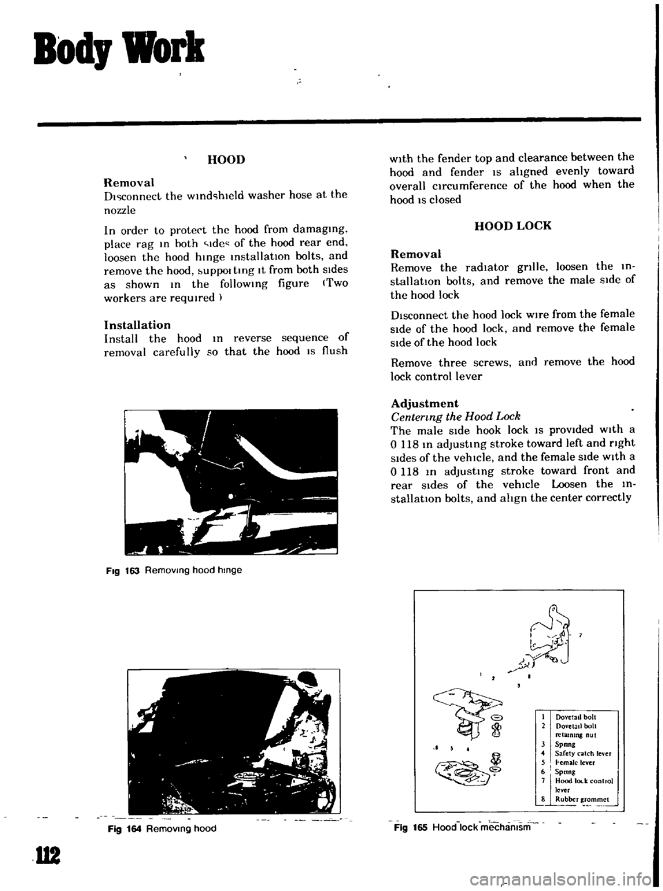
In
order
to
protect
the
hood
from
damaging
place
rag
In
hoth
Ide
of
the
hood
rear
end
loosen
the
hood
hinge
installatIOn
bolts
and
remove
the
hood
UPPOl
tIng
It
from
both
SIdes
as
shown
In
the
follOWing
figure
Two
workers
are
required
Installation
Install
the
hood
In
reverse
sequence
of
removal
carefully
so
that
the
hood
IS
flush
FIg
163
Removmg
hood
hmge
Fig
164
Removmg
hood
U2
with
the
fender
top
and
clearance
between
the
hood
and
fender
IS
aligned
evenly
toward
overall
circumference
of
the
hood
when
the
hood
IS
closed
HOOD
LOCK
Removal
Remove
the
radiator
gnlle
loosen
the
in
stallation
bolts
and
remove
the
male
Side
of
the
hood
lock
Disconnect
the
hood
lock
wire
from
the
female
Side
of
the
hood
lock
and
remove
the
female
Side
of
the
hood
lock
Remove
three
screws
and
remove
the
hood
lock
control
lever
Adjustment
Centermg
the
Hood
Lock
The
male
Side
hook
lock
IS
prOVided
with
a
o
118
In
adjusting
stroke
toward
left
and
nght
Sides
of
the
vehicle
and
the
female
SIde
with
a
0118
In
adjustIng
stroke
toward
front
and
rear
Sides
of
the
vehicle
Loosen
the
in
stallatIOn
bolts
and
align
the
center
correctly
I
Dov
tall
bolt
2
Dovetail
bolt
retammg
nut
31
Spong
4
Sarety
catch
lever
5
I
hmaJc
lever
6
Spnng
j
7JjHood
lod
control
lever
8
Rubber
grommet
Ii
5
4
il
Fig
165
Hood
lock
mechamsm