Page 17 of 136

Bneine
Remove
the
011
pan
and
011
straIner
Remove
the
tImIng
chaIn
cover
and
the
chaIn
tenSlOner
Remove
the
crankshaft
and
camshaft
sprockets
together
WIth
the
timing
chaIn
Fig
21
Tlmmg
cham
cover
removal
I
FIg
22
PIston
and
connectmg
rod
assembly
removal
Fig
23
Rear
011
seal
removal
Rotate
the
engIne
a
quarter
turn
and
remove
the
piston
and
connectIng
rod
assembly
Take
off
the
connectIng
rod
beatings
at
the
same
tIme
and
keep
them
In
order
Rotate
the
engIne
a
quarter
turn
and
remove
the
flywheel
Remove
the
maIn
bearIng
cap
and
the
rear
011
seal
Remove
the
crankshaft
Remove
the
baffie
plate
and
the
crank
case
net
Remove
the
camshaft
after
takIng
off
the
cam
shaft
plate
Remove
the
valve
tfter
Remove
the
piston
rIngs
With
a
tlng
remover
Press
out
the
piston
pIn
With
a
piston
pin
remover
and
an
arbor
press
Remove
the
valves
USIng
a
valve
tfter
Be
careful
not
to
lose
valve
sprIng
seat
011
seal
valve
collet
and
valve
rocker
sprIng
FIg
24
Baffle
plate
and
net
removal
Fig
25
Camshaft
plate
removal
17
Page 18 of 136

Bogioe
0
WAI
CI
o
o
WAIl
Cl
I
Fig
26
Valve
components
FIg
27
Cylinder
head
Cyhnder
head
surface
flatness
Standard
MaxImum
m
m
Al2
Engme
less
than
o
0020
o
0039
INSPECTION
AND
REPAIR
Preparation
Check
the
cyhnder
head
and
cylinder
block
for
traces
of
water
leaks
before
cleaning
Clean
all
parts
to
remove
011
stains
carbon
depoSits
fur
and
other
foreIgn
matters
com
pletely
M
k
s
lr
1at
all
o
hol
Lare
clear
Blow
air
Into
them
If
reqUIred
18
Fig
28
Checking
the
cylinder
head
surface
Fig
29
CheckIng
valve
stem
dIameter
Secure
proper
assembly
carefully
Cylinder
Head
Checking
cylinder
head
mating
face
VIsually
check
for
cracks
and
flaws
Measure
the
surface
of
the
cyhnder
head
on
the
cyhnder
block
SIde
for
warping
If
It
ex
ceeds
the
hmlt
indIcated
below
regrind
afTec
ted
surface
wIth
a
surface
grinder
Valve
Assembly
Check
each
of
the
Intake
and
exhause
valve
assembhes
for
worn
damaged
or
deformed
valve
caps
and
stems
Correct
or
replace
the
valve
If
reqUIred
The
valve
face
or
valve
stem
end
surface
should
be
refaced
by
usmg
a
valve
gtlnder
Notes
a
Deflection
of
seat
surface
against
axis
should
be
0
0012
in
or
less
b
o
rr
ctnes
f
right
angle
and
out
of
round
should
be
0
0004
in
or
less
Page 19 of 136

IBglne
Note
When
the
valve
head
has
been
reduced
to
0
0197
in
or
less
in
thickness
replace
the
valve
Grinding
allowance
for
the
valve
stem
end
surface
is
0
0197
in
or
less
Valve
spring
Measure
the
free
length
and
the
tensIOn
of
each
spnng
If
the
measured
value
exceeds
the
specIfied
hmlt
replace
the
sprlllg
Check
each
spnng
for
deformatIOn
with
a
square
Any
sprmgs
w1th
deflectIOn
of
0
0630
III
or
more
must
be
replaced
Valve
Rocker
Shaft
and
Rocker
Arm
Check
the
valve
rocker
shaft
and
rocker
arm
1
N
in
00
9E
22
N
o
NO
I
I
I
I
1
I
I
Ll
gE
N
cno
CX
co
00
r
o
171M
OtM
Be
22
Bo
l
N
11
lit
l
o
cnM
l
Q
1
45
30
290
to
29
2
die
1142
to
1
1501
N
I
350
to
35
2dla
1
378
to
1386
INTAKE
EXHAUST
UNIT
mm
lnl
Fig
30
The
Intake
and
exhaust
valves
Fig
31
Valve
grinder
for
seizure
and
wear
and
repair
or
replace
as
required
Valve
rocker
arm
to
shaft
011
clearance
o
0008
to
0
0020
III
Spnng
specIficatIOns
Free
length
1
831
In
Valve
closed
1
524
In
at
52
7
Ib
Valve
open
I
19
III
at
1291b
EM
J
Fig
32
Valve
spring
test
Fig
33
Valve
rocker
shaft
lB
Page 20 of 136

Bn
in1l
If
camshaft
bearmg
clearance
IS
exceSS1ve
replace
the
camshaft
bearmgs
with
service
parts
When
valve
contact
surface
of
the
valve
rocker
arm
IS
worn
excessively
m
step
repair
by
means
of
a
valve
grinder
or
replace
Grinding
allowance
for
valve
contact
surface
of
the
valve
rocker
arm
IS
0
0197
In
or
less
Valve
Lifter
and
Push
Rod
Check
the
valve
hfter
for
wear
seizure
and
bevel
edge
contact
and
repair
or
replace
as
reqUIred
Measure
clearance
between
the
hfter
hole
on
the
cyhnder
block
and
valve
hfter
and
replace
the
valve
hfter
when
clearance
ex
ceeds
the
hmlt
Check
the
push
rod
for
bendmg
and
damage
and
repair
or
replace
as
reqUIred
Camshaft
and
Camshaft
Bearing
Measure
mner
dIameter
of
the
camshaft
bearing
and
outer
diameter
of
the
camshaft
Journal
Standard
MaxlIDum
m
m
Valve
hfter
hfter
hole
o
0059
o
0008
to
0
0020
clearance
limit
0151010
00059
m
Standard
003
to
0071010
00012
to
00027
m
Fig
34
Camshaft
bearing
check
20
Valve
Timing
If
the
camshaft
has
no
apparent
damage
although
some
valve
troubles
have
been
detec
Standard
Wear
hm1t
1st
00015luOO024
2nd
00011
to
0
0020
Ot
3rd
clearance
00016
to
00025
o
0059
In
4th
00011
to
0
0020
5th
00015
toO
0024
1st
1
7257
to
I
7261
Inner
2nd
1
7050
to
1
7060
diameter
of
camshaft
3rd
beanng
1
6865
to
1
6868
m
4th
I
6663
to
I
6667
5th
1
6243
to
1
6247
TDC
DIRECTION
OF
ROTATION
EXHAUST
INTAKE
BDC
Fig
35
Valve
timing
diagram
Page 21 of 136

ted
compare
valve
ttmmg
data
wIth
the
valve
I
ttmmg
diagram
to
ensure
that
begmmng
and
endmg
of
stroke
for
all
cylmders
are
com
plymg
with
specified
advance
and
retard
figures
Cylinder
Block
Check
the
cyhnder
head
v1sually
for
defects
such
as
cracks
and
flaws
Measure
the
top
of
the
cyhnder
block
cyhn
der
head
matmg
face
for
warpmg
If
the
warp
exceeds
the
hmlt
correct
1t
Measure
the
cyhnder
bore
for
out
of
round
and
wear
WIth
a
bore
gauge
If
wear
or
out
of
round
IS
exceSS1ve
rebore
the
cyhnder
walls
by
means
of
a
bormg
machme
Umt
degree
a
b
d
f
c
e
248
248
14
54
12
56
Standard
MaxImum
tolerance
Surface
flatness
less
than
o
0020
o
0039
m
Distortion
limIt
0
101010
00039
In
Standard
0051010
100020
In
or
less
Fig
36
Cylinder
block
surface
check
Bogioe
When
wear
or
out
of
round
1S
mmor
and
wlthm
the
hmlt
remove
the
step
from
the
top
most
portIOn
of
the
cyhnder
by
the
use
of
a
ridge
reamer
or
other
slm11ar
tool
Piston
Piston
Pin
and
Piston
Ring
Check
for
seIzure
scratch
and
wear
Replace
as
reqUIred
Measure
Side
clearance
of
each
piston
rmg
and
ring
groove
WIth
the
piston
rmg
mstalled
on
the
piston
Clearance
of
a
new
pIston
and
p1ston
rmg
should
be
as
follows
Place
the
rmg
at
the
bottom
of
the
rmg
traveled
part
of
cyhnder
bore
m
wh1ch
It
wlll
be
used
Wear
limIt
02mm
0
0079
In
I
Fig
37
MeaSUring
the
cylinder
bore
SAO
I
O
I
f
Fig
38
Piston
and
connecting
rod
assembly
II
Page 22 of 136
BogiDe
SIde
clearance
Standard
Wear
limIt
m
m
Top
rIng
o
0079
0015
to
0
0027
2nd
rIng
00015
to
0
0027
o
0079
Ot
rIng
00015
to
0
0031
o
0079
EM129
Fig
39
Side
clearance
measurement
Fig
40
Ring
gap
measurement
22
Rmg
gap
Standard
Wear
limIt
m
m
Top
rmg
o
0394
00079
to
0
0138
2nd
rIng
o
0394
00079
to
00138
OtlrIng
o
0394
00118
to
00354
Fig
41
Piston
pin
fitting
EM131
Fig
42
Measunng
piston
pin
diameter
Page 23 of 136

Square
rmg
m
bore
by
pushing
It
mto
pos1t1on
wIth
the
head
piston
Measure
gap
between
ends
of
rmg
with
feeler
gauge
Gap
should
be
as
hsted
above
Note
a
When
the
piston
ring
only
is
to
be
replaced
without
the
cylinder
bore
bemg
corrected
measure
gap
at
the
bottom
of
the
cylinder
where
the
wear
is
minor
b
Overs1ze
piston
rings
are
avaIlable
for
service
50
100
150
oversize
Measure
the
piston
pm
hole
m
relation
to
the
outer
dIameter
of
the
pm
If
wear
exceeds
the
hmlt
replace
such
piston
pm
together
with
the
pIston
on
whIch
It
IS
mstalled
PI
ton
pill
dldmeter
06869
to
06871
PIston
pill
length
25681
to
5779
Piston
pm
hole
dta
meter
06874
to
0
6871
PIston
pm
to
piston
clearance
00002
to
OOUr
j
Interference
fit
of
piston
pm
to
connectmg
rod
o
0008
EM133
FIg
43
Connecting
rod
ahgner
Bngine
Flttmg
of
piston
pm
Determme
the
fittmg
of
the
piston
pm
mto
the
piston
pm
hole
to
such
an
extent
that
1t
can
be
finger
pressed
at
room
temperature
ThIS
piston
pm
rnust
be
tight
press
fitted
mto
the
connectmg
rod
Connecting
Rod
If
a
connectmg
rod
shows
any
scratch
or
score
mark
or
IS
pitted
on
both
Sides
of
the
thrust
face
and
the
large
end
correct
or
replace
It
Check
for
bend
or
torsIOn
usmg
a
connectmg
rod
ahgner
If
bend
or
torsIOn
exceeds
the
hmlt
correct
or
replace
the
connectmg
rod
When
replacing
the
connectmg
rod
select
the
rod
so
that
weight
difference
between
new
and
old
rods
IS
wlthm
0
18
oz
m
umt
weIght
Standard
MaXimum
Connectmg
rod
bend
bend
or
tOrsIon
per
100
mm
o
0020
or
3
94
m
length
o
00391
torsIOn
o
0028
I
Standard
MaXImum
BIg
end
play
00079
to
0
0118
I
U0157
FIg
44
Big
end
play
check
23
Page 24 of 136

BogiDe
27
00
to
27
05
1063
to
1
0651
1910
to
1940
1910
to
19
40
0752
to
07641
0752
to
0
7641
49951
to
49
964
dl
11
9666
to
1
9671
ALL
MAIN
BEARING
JOURNALS
34
97
to
35
03
1
377
to
1
3791
44
961
to
44
974
dl
1
7701
to
1
7706
ALL
CRANK
PINS
UNIT
mm
m
Fig
45
Crankshaft
S
tanddrd
MaXimum
Taper
out
of
round
of
uank
Journal
and
o
0004
00012
crank
pm
Standard
MaxJmum
Crankshaft
bend
m
o
0006
o
0020
Install
connecting
rods
wIth
bearings
on
to
the
corresponding
crank
pinS
and
measure
the
thrust
clearance
If
the
measured
value
ex
ceeds
the
hmlt
replace
such
connecting
rod
Crankshaft
Check
the
crankshaft
Journal
and
crank
pin
for
scars
biased
wear
and
cracks
Repair
or
replace
as
reqUired
Check
the
crankshaft
for
bend
If
the
bend
ex
ceeds
the
hmlt
replace
the
crankshaft
Note
When
me
8
sJlring
jJ
nc
ldtSe
dial
gauge
14
Standard
Llmtl
Crankshaft
free
end
play
m
o
0020
to
0
0059
00118
EM141
Fig
46
Plasllgage
Bend
value
is
a
half
of
the
readmg
ob
tamed
when
the
crankshaft
is
turned
once
with
the
dial
gauge
applied
to
Its
center
journal
After
regrInding
the
crankshaft
fimsh
It
to
the
necessary
size
by
uSing
an
adequate
un
derSize
bearing
according
to
the
extent
of
reqUIred
repair
Install
the
crankshaft
In
the
cyhnder
block
and
measure
th
the
thruht
clearance
Check
the
main
drIve
shaft
pilot
beating
at
the
rear
end
of
the
crankshaft
for
wear
and
damage
Replace
It
1f
any
defects
are
detected
Bushing
and
Bearing
Check
all
bearIngs
and
bushings
for
seIzure
melt
scar
and
burr
Rgj
Jlace
bushings
If
any
defects
are
detected
Wipe
off
011
and
dust
especially
the
rear
of
the
bushing
Set
the
main
bearing
on
the
cap
block
 1
1 2
2 3
3 4
4 5
5 6
6 7
7 8
8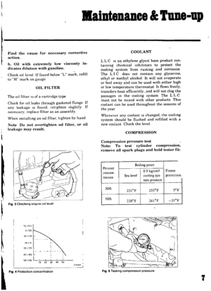 9
9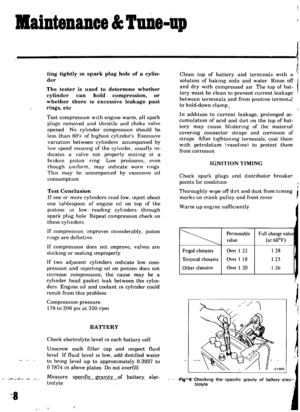 10
10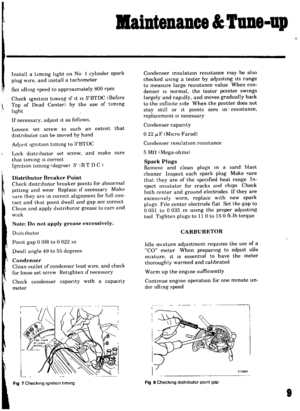 11
11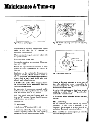 12
12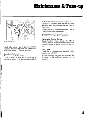 13
13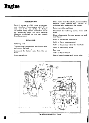 14
14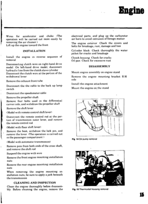 15
15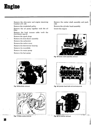 16
16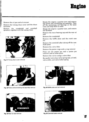 17
17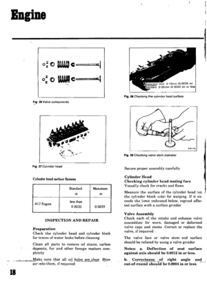 18
18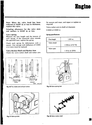 19
19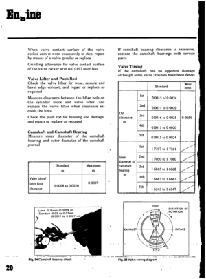 20
20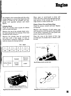 21
21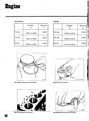 22
22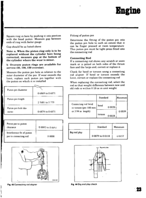 23
23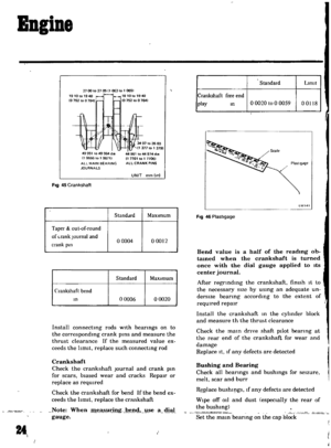 24
24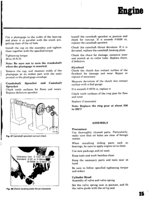 25
25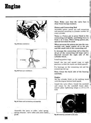 26
26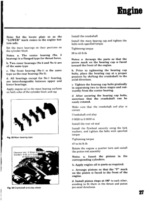 27
27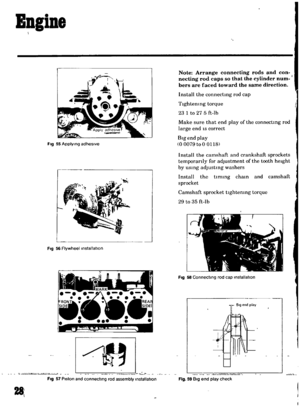 28
28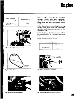 29
29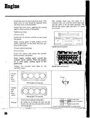 30
30 31
31 32
32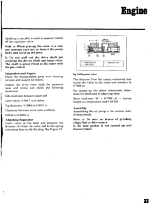 33
33 34
34 35
35 36
36 37
37 38
38 39
39 40
40 41
41 42
42 43
43 44
44 45
45 46
46 47
47 48
48 49
49 50
50 51
51 52
52 53
53 54
54 55
55 56
56 57
57 58
58 59
59 60
60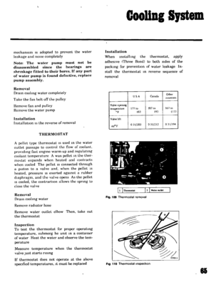 61
61 62
62 63
63 64
64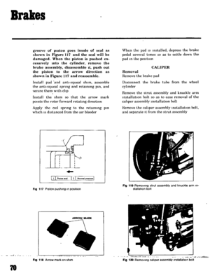 65
65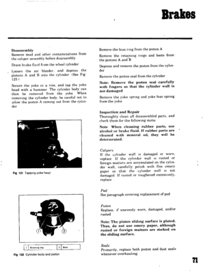 66
66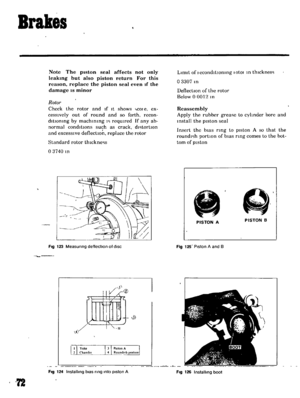 67
67 68
68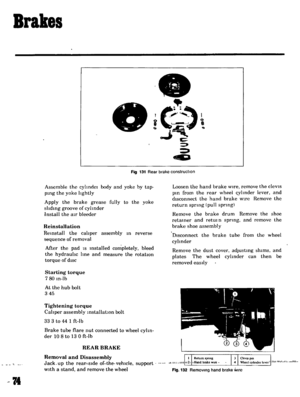 69
69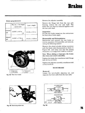 70
70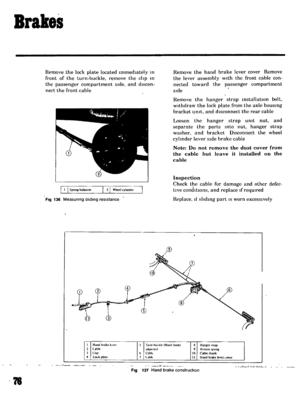 71
71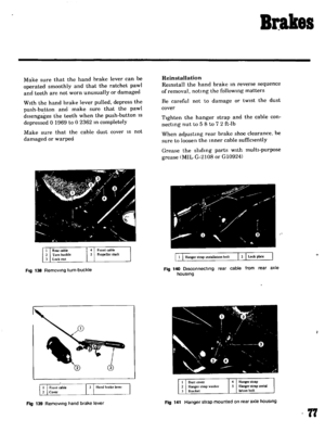 72
72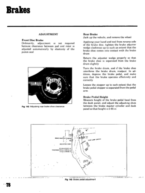 73
73 74
74 75
75 76
76 77
77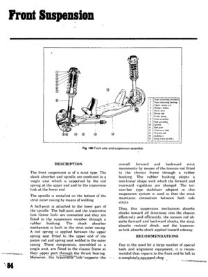 78
78 79
79 80
80 81
81 82
82 83
83 84
84 85
85 86
86 87
87 88
88 89
89 90
90 91
91 92
92 93
93 94
94 95
95 96
96 97
97 98
98 99
99 100
100 101
101 102
102 103
103 104
104 105
105 106
106 107
107 108
108 109
109 110
110 111
111 112
112 113
113 114
114 115
115 116
116 117
117 118
118 119
119 120
120 121
121 122
122 123
123 124
124 125
125 126
126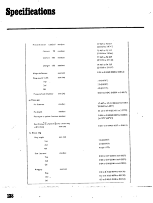 127
127 128
128 129
129 130
130 131
131 132
132 133
133 134
134 135
135