Page 9 of 136

aintenIDce
une
up
Find
the
cause
for
necessary
corrective
action
b
Oil
with
extremely
low
viscosity
in
dicates
dllutton
with
gasoline
Check
011
level
If
found
below
L
mark
refill
to
H
mark
on
gauge
OIL
FILTER
The
011
filter
IS
of
a
cartndge
type
Check
for
011
leaks
through
gasketed
flange
If
any
leakage
IS
found
retIghten
shghtly
If
nece
sary
replaLe
filter
as
an
assembly
When
mstalhng
an
011
filter
tIghten
by
hand
Note
Do
not
overtighten
011
fIlter
or
oil
leakage
may
result
I
I
Fig
3
Checking
engine
011
level
Oc
OF
I
0
121
20141
30
21
401401
5015BI
I
EGOQl
I
10
20
Fig
4
Protection
concentration
COOLANT
L
L
C
IS
al
ethylene
glycol
base
product
con
tammg
chemical
mhlbltors
to
protect
the
coohng
system
from
rustmg
and
corrosIOn
The
L
I
C
does
not
con
tam
any
glycerme
ethyl
or
methyl
alcohol
It
wIll
not
evaporate
or
bOll
away
and
can
be
used
wIth
either
high
or
low
temperature
thermostat
It
flows
freely
transfers
heat
effiCiently
and
will
not
clog
the
passages
m
the
coohng
system
The
L
L
C
must
not
be
mIxed
wIth
other
products
ThiS
coolant
can
be
used
throughout
the
seasons
of
the
year
Whenever
any
coolant
IS
changed
the
coohng
system
should
be
flushed
and
refilled
wIth
a
new
coolant
Check
the
level
COMPRESSION
Compression
pressure
test
Note
To
test
cylinder
compression
remove
all
spark
plugs
and
hold
tester
fit
Percent
BOllIng
pomt
concen
09
kg
cm2
Freeze
tra
lion
Sea
level
coolmg
sys
protectIon
tern
pressure
30
2210F
2550F
50f
50
2280
F
2610F
31oF
ETO
104
Fig
5
Testing
compressIon
pressure
7
Page 10 of 136

aiDtenaDce
TUDe
up
ting
tightly
m
spark
plug
hole
of
a
cylin
der
The
tester
is
used
to
determme
whether
cylinder
can
hold
compression
or
whether
there
IS
excessive
leakage
past
rings
etc
Test
compressIOn
wIth
engme
warm
all
spark
plugs
removed
and
throttle
and
choke
valve
opened
No
cyhnder
compressIOn
should
be
less
than
80
of
highest
cyhnder
s
Excessive
variatIOn
between
cyhnders
accompamed
by
low
speed
missing
of
the
cyllndel
usually
10
dlcates
a
valve
not
properly
seating
or
a
blOken
pIston
ring
Low
preSsures
even
though
umform
may
indIcate
worn
rings
ThIs
may
be
accompamed
by
excessive
011
consumptIOn
Test
Conclusion
If
one
or
more
cyhnders
read
low
Inject
about
one
tablespoon
of
engine
011
on
top
of
the
plstons
In
low
readmg
cyhnders
through
spark
plug
hole
Repeat
compressIOn
check
on
these
cy
II
nders
If
compressIOn
Improves
conSiderably
piston
rings
are
defectIve
If
compressIOn
does
not
Improve
valves
are
stIcking
or
seatIng
Improperly
If
two
adjacent
cyhnders
mdlcate
low
com
pressIOn
and
mjectmg
011
on
pistons
does
not
Increase
compreSSIOn
the
cause
may
be
a
cylInder
head
gasket
leak
between
the
cyhn
ders
Engine
011
and
coolant
In
cylInder
could
result
from
this
problem
CompressIOn
pressure
178
to
206
pSI
at
350
rpm
BATIERY
Check
electrolyte
level
10
each
battery
cell
Unscrew
each
filler
cap
and
Inspect
flUId
level
If
flUId
level
IS
low
add
dIstilled
water
to
bring
level
up
to
approximately
03937
to
07874
In
above
plates
Do
not
overfill
Mea
ure
P
illL
gravlty
of
pattery
el
c
trolyte
8
Clean
top
of
battery
and
terminals
With
a
solutIOn
of
baking
soda
and
water
Rinse
off
and
dry
WIth
compressed
atr
The
top
of
bat
tery
must
be
clean
to
prevent
current
leakage
between
terminals
and
from
poSItive
termlndl
to
hold
down
clamp
In
additIOn
to
current
leakage
prolonged
ac
cumulatIon
of
aCId
and
dirt
on
the
top
of
bat
tery
may
cause
bhstenng
of
the
material
covering
connector
straps
and
corrOSIOn
of
straps
After
tightening
terminals
coat
them
With
petrolatum
vasehnel
to
protect
them
from
corrosIOn
IGNITION
TIMING
Check
spark
plugs
and
dIstributor
breaker
pOints
for
conditIon
I
I
Thoroughly
wipe
off
dIrt
and
dust
from
tlmmg
j
marks
on
crank
pulley
and
front
cover
Warm
up
engine
suffiClently
PermIssIble
Full
charge
value
value
at
68OF
Fngld
chmates
Over
1
22
128
TropIcal
chmates
Over
I
18
123
Other
clunates
Over
1
20
126
j
J
I
ET002
Flg
S
Gheckmg
the
speCific
gravity
of
baltery
elec
trolyte
f
Page 11 of 136

l
aiDteDaDce
UDe
up
Install
a
timing
lIght
on
No
1
cyhnder
spark
plug
WIre
and
Install
a
tachometer
Set
Idhng
ipeed
to
approximately
800
rpm
Check
19mtlOn
tImmg
If
It
IS
50BTDC
Before
Top
of
Dead
Center
by
the
use
of
tlmmg
hght
If
necessary
adjust
It
as
follows
Loosen
iet
screw
to
such
an
extent
that
dlstnbutor
can
be
moved
by
hand
AdJu
it
IgmtlOn
tIming
to
50BTDC
Lock
dlstnbutor
set
screw
and
make
sure
that
tlmmg
IS
correct
IgnitIOn
tImmg
degreel
50
B
T
DC
Distributor
Breaker
Point
Check
dlstnbutor
breaker
pomts
for
abnormal
pItting
and
wear
Replace
If
necessary
Make
wre
they
are
In
correct
ahgnment
for
full
con
tact
and
that
pOint
dwell
and
gap
are
correct
Clean
and
apply
dlstnbutor
grease
to
cam
and
WIck
Note
Do
not
apply
grease
excessively
Dl
tI
IbutOl
POint
gap
0
018
to
0
022
In
Dwell
angle
49
to
55
degrees
Condenser
Clean
outlet
of
condenser
lead
WIre
and
check
for
loose
set
screw
RetIghten
If
necessary
Check
condenber
capacIty
With
a
capacity
meter
Fig
7
Checking
Igmllon
timing
Condenser
msulatlOn
resistance
may
be
also
checked
usmg
a
tester
by
adjusting
ItS
range
to
measure
large
resIstance
value
When
con
denser
IS
normal
the
tester
pomter
swmgs
largely
and
rapidly
and
moves
gradually
back
to
the
Infimte
SIde
When
the
pomter
does
not
stay
still
or
It
pomts
zero
m
reSIstance
replacement
IS
necessary
Condenser
capacIty
022
J
F
MIcro
Farad
Condenser
InsulatIOn
resIstance
5
Mn
Mega
ohms
Spark
Plugs
Remove
and
clean
plugs
In
a
sand
blast
cleaner
Inspect
each
spark
plug
Make
iure
that
they
are
of
the
specified
heat
range
In
ipect
msulator
for
cracks
and
chIps
Check
both
center
and
ground
electrodes
If
they
are
excessIVely
worn
replace
WIth
new
spark
plugs
File
center
electrode
flat
Set
the
gap
to
0031
to
0035
m
USIng
the
proper
adjustIng
tool
Tighten
plugs
to
11
0
to
150
ft
Ib
torque
CARBURETOR
Idle
mixture
adjustment
requIres
the
use
of
a
CO
meter
When
preparIng
to
adjust
Idle
mixture
It
IS
essential
to
have
the
meter
thoroughly
warmed
and
cahbrated
Warm
up
the
engme
suffiCiently
ContInue
engIne
operatIOn
for
one
mmute
un
der
ldhng
speed
I
i
I
I
I
I
I
I
ETOQ4
Fig
8
Checking
dlstnbutor
POint
gap
Page 12 of 136

aiDteDaDce
UDe
up
Adjust
throttle
adjusting
screw
so
that
engme
speed
1S
800
rpm
m
N
positIOn
for
automatic
transmIssIOn
Check
IgnitIOn
tlmmg
If
necessary
adjust
1t
to
the
specIficatIOns
IgnitIOn
timing
50
800
rpm
Adjust
Idle
adjusting
screw
so
that
CO
percen
tage
IS
1
5
t0
5
ff
Repeat
the
adjustments
as
desctlbed
In
steps
3
above
so
that
CO
percentage
IS
15
t0
5
ff
at
800
rpm
Cautions
a
On
automatic
transmission
equipped
model
check
must
be
done
in
the
D
position
Be
sure
to
apply
parking
brake
and
to
lock
both
front
and
rear
wheels
wIth
wheel
chocks
b
Hold
brake
pedal
while
stepping
down
on
accelerator
pedal
Otherwise
car
will
rush
out
dangerously
On
automatic
transmISSIOn
eqUIpped
model
make
sure
that
the
adjustment
has
been
made
wIth
the
selector
lever
In
N
posItion
And
then
check
the
specificatIOns
with
the
lever
In
D
posItion
Insure
that
CO
percent
and
Idle
speed
are
as
follows
Idle
rpm
650
Idle
Limiter
Cap
CO
percentage
Do
not
remove
this
Idle
hm1ter
cap
unless
necessary
If
this
Unit
IS
removed
It
IS
I
with
lever
In
D
PoSitIOn
1
5
t
0
5
k
necessary
to
re
adJust
It
at
the
time
of
In
If
necessary
adjust
by
progIesslvely
turmng
stallatlon
To
adjust
proceed
as
follows
throttle
adJustlng
screw
and
Idle
adJustmg
Make
sure
that
the
percentage
oLCO
contents
screw
until
correct
adjustments
are
made
satisfies
the
specifications
I
I
I
I
J
Fig
9
Checking
spark
plug
gap
10
Throttle
sdJustlnl
screw
Idle
adjust
Inlscrew
Idle
Itmlttc
r
cap
4
Stopper
Fig
10
Throttle
adjusting
screw
and
Idle
adjusting
screw
CARB
STOPPER
Fig
11
Setting
Idle
limiter
cap
Notes
a
Do
not
attempt
to
screw
down
the
idle
adjusting
screw
completely
to
JI
avoid
damage
to
the
tip
which
will
tend
to
cause
malfunctions
b
After
idle
adjustment
has
been
made
I
shift
the
level
to
N
or
P
position
for
automatic
transmission
c
Remove
wheel
chocks
before
startmg
the
car
Page 13 of 136
aiDtenuce
TUDe
up
Fig
12
Fuel
strainer
Install
Idle
hmlter
cap
m
posItion
makmg
sure
that
the
adJustmg
screw
can
further
turn
rotatIOn
m
the
CO
RICH
d1rectlOn
Dash
Pot
Automatic
Transmission
Model
Only
Check
operation
of
dash
pot
It
should
not
be
cracked
or
bound
It
IS
also
essenttal
to
check
r
w
be
certam
that
It
IS
m
correct
adjustment
Check
to
be
sure
that
dash
pot
contacts
stop
per
lever
when
engme
speed
reaches
1
900
to
2
000
rpm
Engme
should
be
slowed
down
from
3
000
to
1
000
rpm
within
a
few
seconds
Readjust
dash
pot
or
replace
It
with
a
new
one
lflt
falls
to
meet
the
above
condItions
Carburetor
Return
Spring
Check
throttle
return
sprmg
for
sign
of
damage
wear
or
squareness
Discard
spring
If
found
wIth
any
of
above
excessIvely
beyond
use
Fuel
Filter
Check
for
a
contammatlOn
element
water
depoSIt
and
defection
All
engmes
use
a
cartridge
type
strainer
If
1t
IS
found
to
be
defective
replace
as
an
assembly
u
Page 14 of 136
IQgiDe
DESCRIPTION
The
A12
engme
IS
a
715
cu
m
In
I
me
over
head
valve
four
cyltnder
engine
with
2874
m
bore
and
2
765
m
stroke
It
feature
full
opened
wedge
shaped
combustIOn
cham
ber
alummum
heads
and
fully
balanced
5
bearmg
crankshaft
to
turn
out
smooth
dependable
power
REMOVAL
Removmg
hood
Open
the
hood
remove
four
mstallatlOn
bolts
and
remove
the
hood
Disconnect
the
battery
cable
from
the
ter
mmal
Removmg
radIator
Dram
water
from
the
radiator
disconnect
two
radIator
hoses
remove
four
radIator
m
stallatlOn
bolts
and
remove
the
radiator
Removmg
cables
and
hoses
Disconnect
the
followmg
cables
hoses
and
wires
High
voltage
cable
between
Igmtton
COlI
and
distributor
Cable
to
the
thermal
transmitter
Cable
to
the
011
pressure
sW1tch
Cable
to
the
primary
Side
of
the
distributor
Cable
to
the
startmg
motor
Fuel
hose
Cable
to
the
alternator
Heater
hose
for
model
With
heater
only
I
Fig
13
Sectional
view
of
A
12
Engine
It
Page 15 of 136

Bngine
WIres
for
accelerator
and
choke
The
operatIOn
Will
be
carned
out
more
easily
by
removing
the
a1r
cleaner
Lift
up
the
engine
toward
the
front
INST
ALLA
TION
Install
the
engine
In
reverse
sequence
of
removal
Disconnecting
clutch
wire
on
nght
hand
dnve
model
On
left
hand
dnve
model
disconnect
hydraulIc
line
from
the
clutch
slave
cylInder
DIsconnect
the
clutch
WIre
at
the
JXlrtlOn
of
the
wIthdrawal
lever
Remove
the
exhaust
front
tube
Disconnect
the
the
cable
to
the
back
up
lamp
SWItch
D1sconnect
the
speedometer
cable
Remove
the
propeller
shaft
Remove
four
bolts
used
In
the
differential
carner
SIde
and
Withdraw
the
propeller
shaft
Remove
the
shift
lever
Model
With
remote
control
shIft
lever
Disconnect
the
remote
control
rod
at
the
JXlr
tlOn
of
transmiSSIOn
outer
lever
and
remove
the
remote
control
rod
Model
With
floor
Sh1ft
lever
Remove
the
boot
WIthdraw
the
lock
pin
and
remove
the
lever
The
operatIOn
IS
carned
out
In
the
passenger
compartment
Model
With
automatic
transmiSSIOn
Remove
pinS
from
both
ends
of
the
cross
shaft
and
remove
the
shIft
rod
Suspend
the
engine
With
wire
Remove
the
front
engine
mounting
installation
nuts
Remove
the
rear
engine
mounting
installation
nuts
When
removing
the
engine
mounting
in
stallation
nuts
be
sure
to
apply
a
Jack
beneath
the
transmiSSIOn
CLEANING
AND
INSPECTION
Clean
the
engine
thoroughly
before
disassem
bly
Before
cleaning
the
engine
remove
the
l
electncal
parts
and
plug
up
the
carburetor
air
horn
to
aVOid
intrusIOn
of
foreign
matter
The
engine
extenor
Check
the
covers
and
bolts
for
breakage
rust
damage
and
loss
CylInder
block
Check
thoroughly
the
water
Jacket
for
cracks
and
breakage
Clutch
hOUSing
Check
for
cracks
011
pan
Check
for
excessive
rust
DISASSEMBLY
Mount
engine
assembly
on
engine
stand
Remove
the
engine
mounting
bracket
R
H
Side
Install
the
engine
attachment
Mount
the
engine
on
the
stand
Fig
14011
pump
removal
Fig
15
Thermostat
hOUSing
removal
II
Page 16 of 136
Bngine
Remove
the
altel
nator
and
engine
mounting
bracket
L
H
slde
Remove
the
crankshaft
pulley
Remove
the
011
pump
together
With
the
011
filtel
Remove
the
high
tensIOn
cable
wIth
the
dlstnbutor
cap
on
Remove
the
spark
plugs
Remove
the
dlstllbutor
assembly
Remove
the
carburetor
Remove
the
rocker
cover
Remove
the
thermo
itat
houslllg
Remove
the
manifolds
Remove
the
water
pump
Remove
the
fuel
pump
Fig
16
Manifolds
removal
Fig
17
Water
pump
removal
18
Remove
the
rocker
shaft
assembly
and
push
rods
Remove
the
cylInder
head
assembly
Invert
the
engine
Fig
18
Rocker
shaft
assembly
removal
7
1
l
I
h
Y
r
I
w
L
1
Fig
19
Cylinder
head
bolts
removal
sequence
o
Fig
20
011
strainer
removal
j
 1
1 2
2 3
3 4
4 5
5 6
6 7
7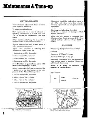 8
8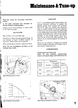 9
9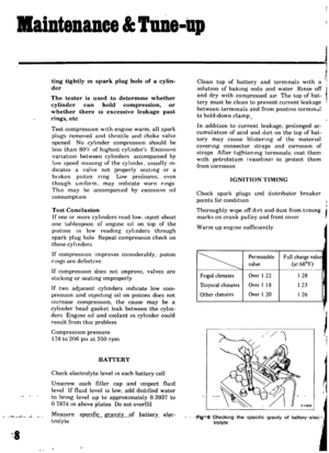 10
10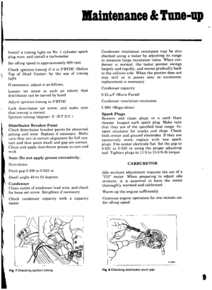 11
11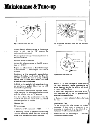 12
12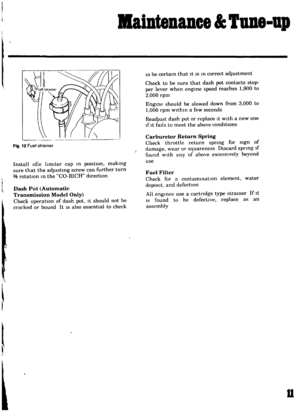 13
13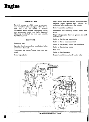 14
14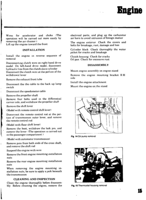 15
15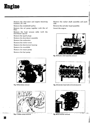 16
16 17
17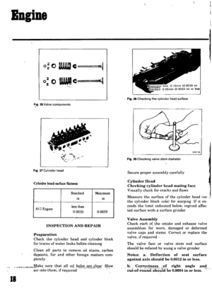 18
18 19
19 20
20 21
21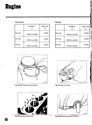 22
22 23
23 24
24 25
25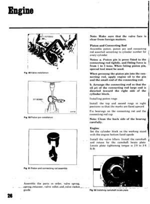 26
26 27
27 28
28 29
29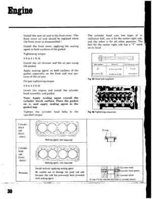 30
30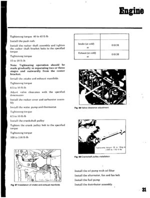 31
31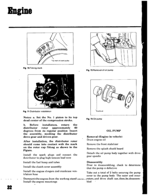 32
32 33
33 34
34 35
35 36
36 37
37 38
38 39
39 40
40 41
41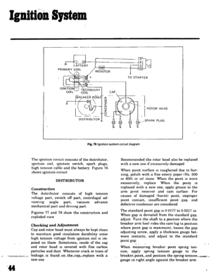 42
42 43
43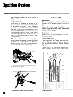 44
44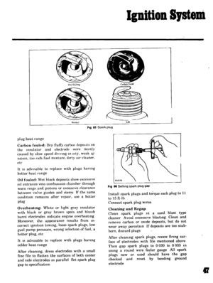 45
45 46
46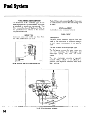 47
47 48
48 49
49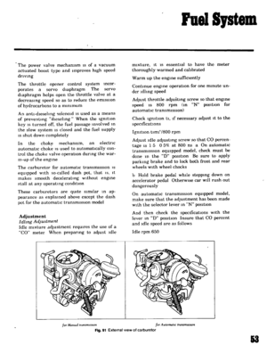 50
50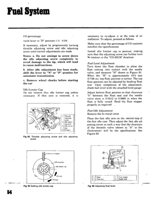 51
51 52
52 53
53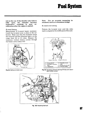 54
54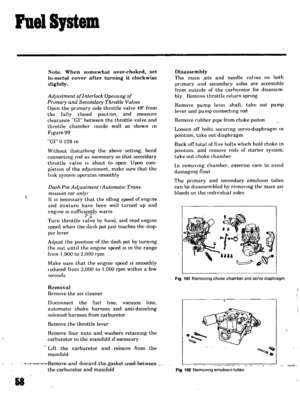 55
55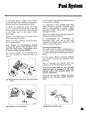 56
56 57
57 58
58 59
59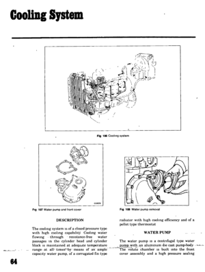 60
60 61
61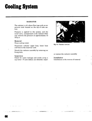 62
62 63
63 64
64 65
65 66
66 67
67 68
68 69
69 70
70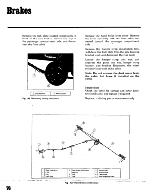 71
71 72
72 73
73 74
74 75
75 76
76 77
77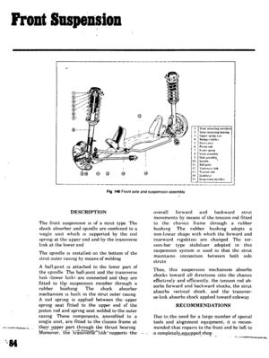 78
78 79
79 80
80 81
81 82
82 83
83 84
84 85
85 86
86 87
87 88
88 89
89 90
90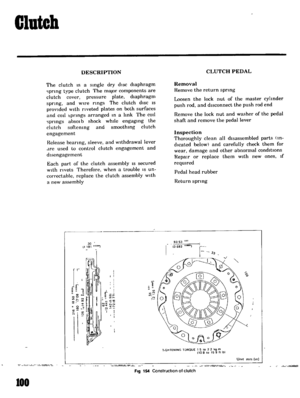 91
91 92
92 93
93 94
94 95
95 96
96 97
97 98
98 99
99 100
100 101
101 102
102 103
103 104
104 105
105 106
106 107
107 108
108 109
109 110
110 111
111 112
112 113
113 114
114 115
115 116
116 117
117 118
118 119
119 120
120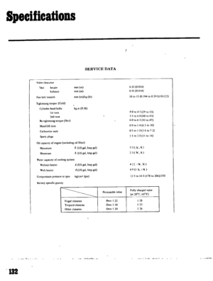 121
121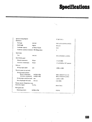 122
122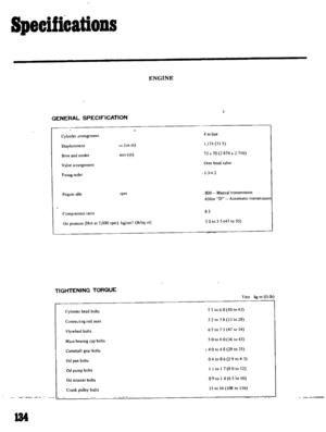 123
123 124
124 125
125 126
126 127
127 128
128 129
129 130
130 131
131 132
132 133
133 134
134 135
135

