Page 25 of 136

Ingine
1
Cut
a
plastIgage
to
the
wIdth
of
the
bearing
and
place
It
m
parallel
with
the
crank
pm
gettmg
clear
of
the
011
hole
Install
the
cap
on
the
assembly
and
tighten
them
together
with
the
specified
torque
Tlghtentng
torque
36
to
43
ft
lb
Note
Be
sure
not
to
turn
the
crankshaft
when
the
plastIgage
is
Inserted
Remove
the
cap
and
measure
wIdth
of
the
plastlgage
at
Its
widest
part
wIth
the
scale
printed
tn
the
plastIgage
envelope
Crankshaft
Sprocket
and
Camshaft
Sprocket
Check
tooth
surfaces
for
flaws
and
wears
Replace
defective
sprocket
EM148
Fig
47
Camshaft
sprocket
run
out
check
Clearance
limit
0
1
mm
00039
m
1
Standard
0
02
to
0
08mm
0
0008
to
0
0031
m
t
Fig
48
Check
locatmg
plate
thrust
clearance
Install
the
camshaft
sprocket
m
posItion
and
check
for
run
out
If
It
exceeds
00039
tn
replace
the
camshaft
sprocket
Check
the
camshaft
thrust
deViatIOn
If
It
IS
deViated
replace
the
camshaft
locatmg
plate
Check
the
cham
for
damage
excessive
wear
and
stretch
at
ItS
roller
Imks
Replace
cham
If
defective
Flywheel
Check
the
clutch
diSC
contact
surface
of
the
flywheel
for
damage
and
wear
Repair
or
replace
If
necessary
Measure
deVtat10n
of
the
clutch
dISC
contact
surface
with
a
dial
gauge
If
It
exceeds
0
0079
m
replace
1t
Check
tooth
surfaces
of
the
ring
gear
for
flaw
and
wear
Replace
If
necessary
Note
Replace
the
ring
gear
at
about
356
to
392
F
ASSEMBLY
PrecautIOn
Use
thoroughly
cleaned
parts
PartIcularly
make
sure
that
011
holes
are
cleal
of
foreign
matter
When
mstalltng
sltdmg
parts
such
as
bearings
be
sure
to
apply
engme
011
to
them
Use
new
packmgs
and
011
seals
Keep
tools
and
work
benches
clean
Keep
the
necessary
parts
and
tools
near
at
hand
Be
sure
to
follow
specified
tIghtemng
torque
and
orders
Cylinder
Head
Assembly
of
valve
and
valve
sprmg
Set
the
valve
sprmg
seat
m
poSItIon
and
fit
the
valve
gUIde
with
the
011
hp
seal
21
Page 26 of 136

BDgiDe
Fig
49
Valve
installatIon
STl
303001
EM156
Fig
50
Piston
pin
installation
FIg
51
Piston
and
connecting
rod
assembly
Assemble
the
parts
In
order
valve
sprmg
spnng
retamer
valve
collet
and
val
ve
rocker
gUIde
28
Note
Make
sure
that
the
valve
face
is
clear
from
foreign
matters
Piston
and
Connecting
Rod
Assemble
pIston
piston
pm
and
connecting
rod
assorted
accordmg
to
cyhnder
number
for
every
cylInder
Notes
a
P1ston
pin
is
press
fitted
to
the
connectmg
rod
tightly
and
fitting
force
is
from
1
to
3
tons
When
fitting
piston
pin
speCIal
tool
must
be
used
When
pressmg
the
piston
pin
into
the
con
necting
rod
apply
engine
oil
to
the
pin
and
the
small
end
of
the
connecting
rod
b
Arrange
the
connecting
rod
so
that
the
oil
Jet
of
the
connecting
rod
large
end
is
directed
toward
the
right
side
of
the
cylinder
block
InstallIng
piston
rmgs
Install
the
top
and
second
rings
In
nght
pOSItIOns
so
that
the
marks
are
faced
upward
FIX
bearings
on
the
connecting
rod
and
the
connecting
rod
cap
Note
Clean
the
back
side
of
the
bearmg
carefully
Engine
Set
the
cyhnder
block
on
the
workmg
stand
WIth
the
engine
bottom
faced
upSIde
Install
the
valve
hfters
Install
the
camshaft
and
retain
by
the
camshaft
locate
plate
Locate
plate
tightemng
torque
IS
2
9
to
3
6
ft
lb
Fig
52
Installing
camshaft
locate
plate
Page 27 of 136

Bogine
Note
Set
the
locate
plate
so
as
the
LOWER
mark
comes
to
the
engine
bot
tom
side
Set
the
maIn
bearIngR
on
theIr
posItIOns
on
the
cylinder
block
Notes
a
The
center
bearmg
No
3
bearmg
is
a
flanged
type
for
thrust
force
b
Two
lOner
bearmgs
No
2
and
No
4
are
of
the
same
type
c
The
front
bearmg
No
1
IS
the
same
type
as
the
rear
bearmg
No
5
d
All
bearings
except
for
No
I
bearing
are
interchangeable
between
upper
and
lower
bearings
Apply
engIne
OIl
to
the
mam
bearIng
surfaces
on
both
sIdes
of
the
cyltnder
block
and
cap
Fig
53
Mam
bearing
caps
Fig
54
Crankshaft
end
play
check
Install
the
crankshaft
Install
the
mam
bearmg
cap
and
tighten
the
bolts
with
specified
torque
Tlghtemng
torque
36
to
43
ft
Ib
Notes
a
Arrange
the
parts
so
that
the
arrow
mark
on
the
bearing
cap
IS
faced
toward
the
front
of
the
engine
b
Prior
to
tightening
the
bearing
cap
bolts
place
the
bearing
cap
at
a
proper
posItIon
by
shlftmg
the
crankshaft
in
the
axial
direction
c
Tighten
the
bearmg
cap
bolts
gradually
in
separatmg
two
to
three
stages
and
out
wardly
from
the
center
bearing
d
After
securing
the
bearing
cap
bolts
ascertam
that
the
crankshaft
can
be
easily
rotated
Make
sure
that
the
crankshaft
end
play
IS
correct
Crankshaft
end
play
o
0020
to
0
0059
In
I
nstalI
the
rear
011
seal
Install
the
flywheel
securely
USIng
the
lock
washers
and
tighten
the
bolts
with
specIfied
torque
Tlghtemng
torque
47
to
54
ft
Ib
Rotate
the
engine
a
quarter
turn
and
mstall
the
piston
rod
assembly
Notes
a
Insert
the
pistons
in
the
corresponding
cyhnders
b
Apply
engine
oil
to
parts
as
required
c
Arrange
pistons
so
that
the
F
mark
on
the
piston
IS
faced
to
the
front
of
the
engine
d
Install
piston
rings
at
18
Y
to
each
other
avoIdIng
to
fit
them
In
the
thrust
and
pIston
pIn
aXial
directIOns
27
Page 28 of 136
Bagine
Fig
55
ApplYing
adhesive
L
FIg
56
Flywheel
installation
c
0
FIg
57
Piston
and
connecting
rod
assembly
installation
281
Note
Arrange
connecting
rods
and
con
necting
rod
caps
so
that
the
cylinder
num
bers
are
faced
toward
the
same
direction
Install
the
connectmg
rod
cap
Tlghtenmg
torque
23
1
to
27
5
ft
lb
Make
sure
that
end
play
of
the
connectmg
rod
large
end
IS
correct
Big
end
play
00079
to
0
0118
Install
the
camshaft
and
crankshaft
sprockets
temporarily
for
adjustment
of
the
tooth
height
by
usmg
adJustmg
washers
Install
the
tlmmg
cham
and
camshaft
sprocket
Camshaft
sprocket
tlghtemng
torque
29
to
35
ft
lb
FIg
58
Connecting
rod
cap
installation
Fig
59
Big
end
play
check
Page 29 of 136
Bogine
HeIght
dIfference
less
than
0
0197
III
AdJustmg
washer
0006
tluckness
m
Fig
60
AdJustmg
sprocket
tooth
heIght
a
IT
Match
mark
e
8
Tlsnaft
0w
1
hol
0
0
0
Matohma
k
Key
groove
Fig
61
Settmg
cham
r
f
r
0
tt
I
I
l
f
I
4
Fig
62
Cham
tensloner
Installation
Notes
a
Make
sure
that
the
camshaft
sprocket
dowel
hole
and
crankshaft
sprocket
key
are
in
line
and
both
the
dowel
hole
and
key
are
located
down
ward
b
Set
the
timing
cham
making
its
mating
marks
meet
with
those
of
crankshaft
sprocket
and
camshaft
sprocket
at
the
right
hand
side
Install
the
tlmmg
cham
tenslOner
and
tighten
the
tenslOner
bolts
to
a
torque
of
43
to
58
ft
Ib
Install
the
crankshaft
011
thrower
Check
the
temloner
spondle
projection
Wear
limit
Spindle
projection
t
Fig
63
Carn
sprocket
gear
mstallatlon
Fig
64
Checkmg
the
tension
spindle
projection
21
Page 30 of 136

BDgiDe
Install
the
new
011
seal
to
the
front
cover
The
front
cover
011
seal
should
be
replaced
when
the
front
cover
IS
disassembled
Install
the
front
cover
applYing
the
seahng
agent
to
both
surfaces
of
the
gasket
Tlghtemng
torque
36
to
5
1
ft
lb
Install
the
ot
strainer
and
the
011
pan
uSing
the
gasket
Apply
seahng
agent
on
both
surfaces
of
the
gasket
especIally
on
the
front
and
rear
por
tlOns
of
the
011
pan
011
pan
tlghtemng
torque
2
9
to
4
3
ft
lb
Invert
the
engine
and
Install
the
cyhnder
head
assembly
and
gasket
Note
Apply
sealing
agent
overall
the
cylinder
block
surface
Place
the
gasket
on
It
and
apply
sealing
agent
to
the
gasket
top
Tighten
the
cylinder
head
bolts
to
the
peclfied
torque
Cylmder
bloLk
Side
Stecl
heet
Sealmg
agent
not
required
Cylinder
head
Side
Jomt
sheet
Remarks
Install
WIthout
applymg
sealing
agent
Be
careful
not
to
damage
the
push
rod
Side
because
thIS
SIde
has
prevIOusly
been
provIded
WIth
sealing
agent
J
30
v
o
The
cyhnder
head
uses
two
types
of
in
stallatIOn
bolt
one
IS
for
the
center
nght
SIde
and
the
other
IS
for
all
other
posItIOns
The
bolt
for
the
center
nght
Side
has
a
I
mark
on
ItS
head
L
1
Bolt
number
hh
nlltilatlOn
rJ
Dlaml
tl
f
j
031111003189
T
T
1M
E
u
pt
lor
CD
03492
to
0
3555
ot
rhJ
FIg
65
Head
bolt
segment
Fig
66
Tlghtenmg
sequence
O
rmg
4
ItI
CYlmder
head
Cylinder
h
ad
gasket
Cylinder
block
o
rtng
To
be
mserted
mto
hole
m
cylmder
block
Page 31 of 136

BDgiDe
TIghtening
torque
40
to
43
ft
Ib
Install
the
push
rod
Install
the
rocker
haft
assembly
and
tighten
the
I
ocker
haft
bracket
bolts
to
the
specIfied
torque
Tightening
torque
15
to
18
ft
lb
Note
TIghtening
operation
should
be
made
gradually
10
separating
two
or
three
stages
and
outwardly
from
the
center
bracket
In
tall
the
Intake
and
exhaust
mamfolds
TIghtening
torque
65
to
10
ft
lb
AdJu
t
valve
clemance
wIth
the
specIfied
dlmenblOn
Install
the
rocker
cover
and
carburetor
assem
bly
I
n
tdll
the
watel
pump
and
thermostat
Tlghtemng
tOl
que
65
to
10
ft
lb
I
nstall
the
crankshaft
pulley
Tighten
the
crank
pulley
bolt
to
the
specIfied
torque
TIghtenIng
torque
109
to
116
ft
lb
Fig
67
Installation
of
Intake
and
exhaust
manifolds
Intake
at
cold
00138
In
Exhaust
at
cold
00138
In
Fig
68
Valve
clearance
adjustment
TlqhtCnlnq
torque
15
to
16kg
m
109
to
116ltlb
Fig
69
Crankshaft
pulley
installation
Install
the
at
pump
with
011
filter
Install
the
alternator
fan
and
fan
belt
Install
the
fuel
pump
Install
the
dlstnbutor
assembly
31
Page 32 of 136

BBgiBe
Fig
70
Tlmmg
mark
Fig
71
Dlstnbutor
mstallatlon
Notes
a
Set
the
No
1
piston
to
its
top
dead
center
of
the
compression
stroke
b
Before
installation
return
the
distributor
rotqr
approximately
60
degrees
from
Its
regular
position
Insert
the
assembly
meshing
the
distributor
drive
gear
and
driven
gear
After
installation
the
distributor
rotor
should
come
into
contact
wIth
the
mark
on
the
rotor
cap
fittmg
as
shown
in
the
Figure
Install
the
spark
plugs
and
connect
the
distrIbutor
to
plug
high
tensIOn
lead
wire
Install
the
fuel
hoses
and
tubes
Install
the
clutch
cover
assembly
Install
the
engme
shngers
and
crankcase
ven
tilatIOn
hose
Fig
72
Removal
of
011
pump
TrochoId
Fig
73011
pump
OIL
PUMP
Removal
Engine
in
vehlCIe
Dram
engme
OIl
Remove
the
front
stabilIzer
Remove
the
splash
shield
board
Detach
the
011
pump
body
together
with
drIve
gear
spmdle
Disassembly
PrIor
to
dlsassembhng
check
to
determme
that
the
pump
IS
defective
Take
out
a
total
of
2
bolts
securmg
the
pump
cover
to
the
pump
body
The
outer
and
mner
Dlsmount
the
engme
from
the
workmg
stand
rotors
and
drive
shaft
can
then
be
dlsassem
Install
the
engme
mountmgs
bled
32
 1
1 2
2 3
3 4
4 5
5 6
6 7
7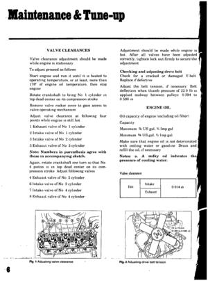 8
8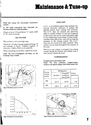 9
9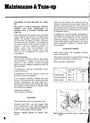 10
10 11
11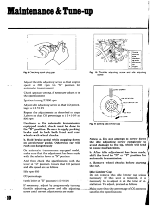 12
12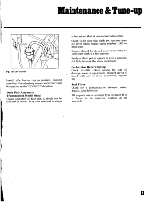 13
13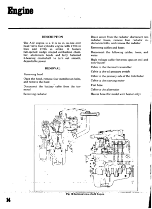 14
14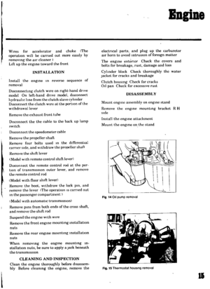 15
15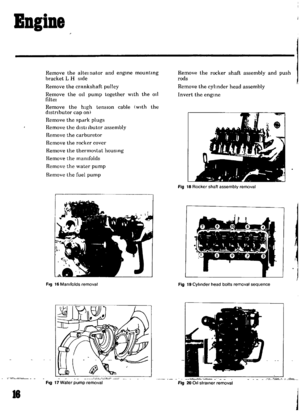 16
16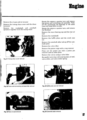 17
17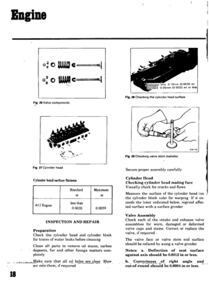 18
18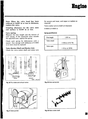 19
19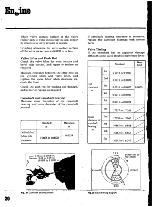 20
20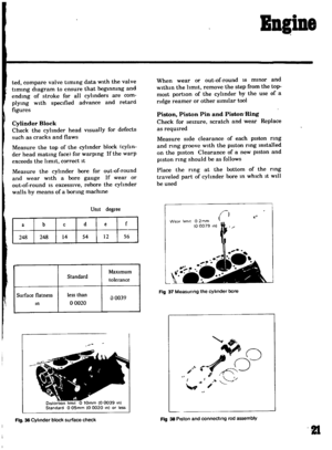 21
21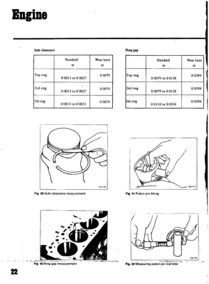 22
22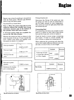 23
23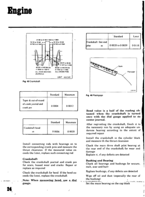 24
24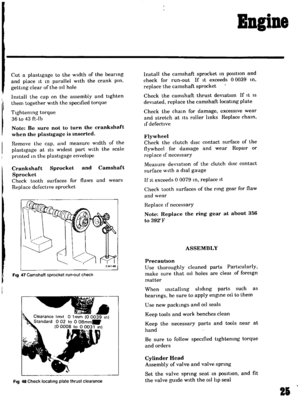 25
25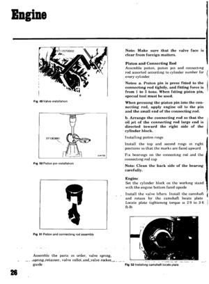 26
26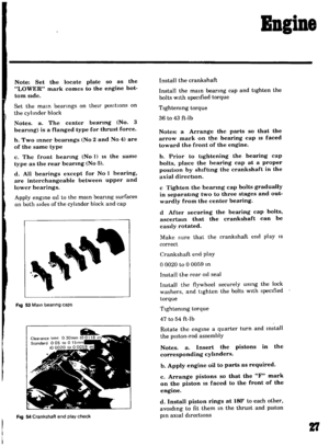 27
27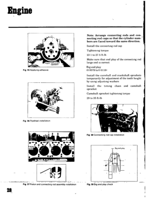 28
28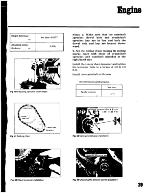 29
29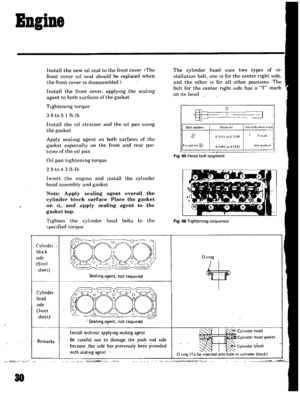 30
30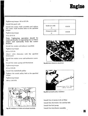 31
31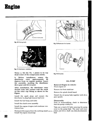 32
32 33
33 34
34 35
35 36
36 37
37 38
38 39
39 40
40 41
41 42
42 43
43 44
44 45
45 46
46 47
47 48
48 49
49 50
50 51
51 52
52 53
53 54
54 55
55 56
56 57
57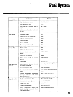 58
58 59
59 60
60 61
61 62
62 63
63 64
64 65
65 66
66 67
67 68
68 69
69 70
70 71
71 72
72 73
73 74
74 75
75 76
76 77
77 78
78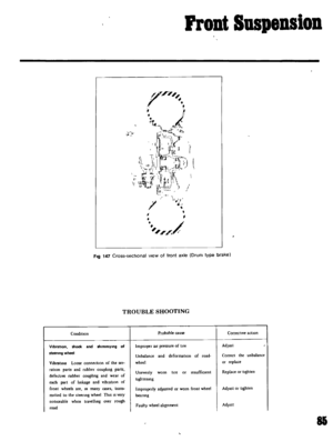 79
79 80
80 81
81 82
82 83
83 84
84 85
85 86
86 87
87 88
88 89
89 90
90 91
91 92
92 93
93 94
94 95
95 96
96 97
97 98
98 99
99 100
100 101
101 102
102 103
103 104
104 105
105 106
106 107
107 108
108 109
109 110
110 111
111 112
112 113
113 114
114 115
115 116
116 117
117 118
118 119
119 120
120 121
121 122
122 123
123 124
124 125
125 126
126 127
127 128
128 129
129 130
130 131
131 132
132 133
133 134
134 135
135
