Page 65 of 136

Brakes
groove
of
pIston
goes
insIde
of
seal
as
shown
in
Figure
117
and
the
seal
will
be
damaged
When
the
piston
is
pushed
ex
cesslvely
mto
the
cylinder
remove
the
brake
assembly
disassemble
It
push
out
the
piston
to
the
arrow
direction
as
shown
in
Figure
117
and
reassemble
Install
pad
and
antt
squeal
shim
assemble
the
anti
squeal
spring
and
retaining
pin
and
ecure
them
with
cltp
Install
the
shim
so
that
the
arrow
mark
pOints
the
rotor
forward
rotating
directIOn
Apply
the
COIl
spring
to
the
retaining
pin
which
IS
distanced
from
the
atr
bleeder
111
PlSton
seal
I
2
I
Normal
position
I
Fig
117
Piston
pushIng
In
posllIon
FIg
118
Arrow
mark
on
shim
78
When
the
pad
IS
Installed
depress
the
brake
pedal
several
tl
mes
so
as
to
settle
down
the
pad
In
the
posltton
CALIPER
Removal
Remove
the
brake
pad
DIsconnect
the
brake
tube
from
the
wheel
cyltnder
Remove
the
strut
assembly
and
knuckle
arm
installatIOn
bolt
so
as
to
ease
removal
of
the
cahper
assembly
installatIOn
bolt
Remove
the
cahper
assembly
installatIOn
bolt
and
separate
It
from
the
strut
assembly
Fig
119
RemOVing
strut
assembly
and
knuckle
arm
in
stallatIon
bolt
Fig
120
RemOVing
caliper
assembly
Installallon
bolt
Page 66 of 136

Brakes
DIsassembly
Remove
mud
and
other
contamInations
from
the
caLiper
as
embly
before
dlsa
sembly
DraIn
bl
ake
fluId
flOm
the
wheel
cylinder
Loosen
the
aIr
bleeder
and
depres
the
pistons
A
and
B
Into
the
cylInder
See
FIg
125
Secure
the
yoke
In
a
vIse
and
tap
the
yoke
head
with
a
hammer
The
cylinder
body
can
then
be
removed
from
the
yoke
When
remOVIng
the
cylinder
body
be
careful
not
to
allow
the
piston
A
comIng
out
from
the
cylIn
der
FIg
121
TapPing
yoke
head
5
I
B
Q
Retamlng
nng
J
Boot
Fig
122
Cylinder
body
and
piston
Remove
the
bIas
nng
from
the
piston
A
Remove
the
retaInIng
nngs
and
boots
from
the
pistons
A
and
B
Depress
and
remove
the
piston
from
the
cylin
der
Remove
the
piston
seal
from
the
cylinder
Note
Remove
the
p1ston
seal
carefully
w1th
fmgers
so
that
the
cylinder
wall
is
not
damaged
Remove
the
yoke
prIng
and
yoke
bias
sprIng
from
the
yoke
Inspection
and
Repair
Thoroughly
clean
all
dIsassembled
parts
and
check
them
for
the
follOWIng
Items
Note
When
cleaning
rubber
parts
use
alcohol
or
brake
fluid
If
rubber
parts
are
cleaned
wIth
mmeral
Oil
they
will
be
detenorated
Calzpers
If
the
cylInder
wall
IS
damaged
or
worn
replace
If
the
cylinder
wall
IS
rusted
or
foreIgn
matters
are
accumulated
on
the
cylIn
der
wall
carefully
polIsh
wIth
fine
emery
paper
so
that
the
cylInder
wall
IS
not
damaged
If
rusted
or
roughened
excessively
replace
Pad
See
paragraph
covenng
replacement
of
pad
PIston
Replace
If
unevenly
worn
damaged
and
or
rusted
Note
The
piston
slidmg
surface
is
plated
Thus
do
not
use
emery
paper
although
rusted
or
foreign
matters
are
sttcked
on
the
sliding
surface
Seals
Prlmanly
replace
both
pIston
and
dust
seals
whenever
overhauling
n
Page 67 of 136
Brakes
Note
The
piston
seal
affects
not
only
Ieakmg
but
also
piston
return
For
this
reason
replace
the
piston
seal
even
If
the
damage
IS
minor
Rotor
Check
the
rotor
and
If
It
shows
cOl
e
ex
cesslvely
out
of
round
and
so
forth
recon
ditIOnIng
by
machInIng
l
l
requIred
If
any
ab
normal
condItIOns
such
as
crack
dl
ltortlOn
and
excessIve
deflectIOn
replace
the
rotor
Standard
rotor
thlckne
ls
03740
In
Fig
123
MeaSUring
deflectoon
of
diSC
Fig
124
Installing
bias
ring
mto
piston
A
72
LImIt
of
I
econdltlOntng
lotOl
In
thlcknes
l
o
3307
In
DeflectIOn
of
the
rotor
Below
0
0012
In
Reassembly
Apply
the
rubber
grea
le
to
cylinder
bore
and
Install
the
pIston
seal
Insert
the
bIas
rIng
to
pIston
A
so
that
the
roundl
lh
portIon
of
bIas
ring
comes
to
the
bot
tom
of
pIston
A
PISTON
B
PISTON
A
Fig
125
Piston
A
and
B
Fig
126
Installing
boot
Page 68 of 136
Brakes
Note
Be
careful
not
to
confuse
the
piston
A
with
B
Apply
rubber
grease
hghtly
to
the
shdlng
par
tlon
of
p1ston
and
Insert
the
piston
Into
the
cyhnder
Note
When
insertmg
the
piston
be
careful
not
to
insert
too
far
Install
the
boot
and
retaining
nng
Install
so
that
the
yoke
groove
of
bIas
nng
of
piston
A
COinCide
wIth
the
yoke
groove
of
cyhnder
YOKE
SPRING
Fig
127
Installation
of
yoke
spnng
1
Fig
128
InstallatIOn
of
yoke
spnng
2
Install
so
that
the
projected
portIOn
of
yoke
spnng
faces
to
diSC
as
shown
In
Figures
127
and
128
Install
the
bias
spring
to
yoke
so
that
the
bias
spring
comes
to
the
aIr
bleeder
Side
of
cyhn
der
Apply
the
brake
grease
to
the
yoke
shdlng
portIOn
of
cylinder
With
the
yoke
spring
Inserted
to
cylinder
groove
hghtly
correct
poSitIOn
of
the
bias
spnng
so
that
the
groove
of
biaS
spring
COin
Cides
With
yoke
Fig
129
Correctmg
bias
spnng
POSItion
Fig
130
Measunng
startmg
torque
73
Page 69 of 136

Brakes
c
Fig
131
Rear
brake
construction
Assemble
the
cylIndel
body
and
yoke
by
tap
ping
the
yoke
lIghtly
Apply
the
brake
grease
fully
to
the
yoke
slIding
groove
of
cylInder
I
nstall
the
air
bleeder
Reinstallation
Reinstall
the
calIper
assembly
In
reverse
sequence
of
removal
After
the
pad
IS
Installed
completely
bleed
the
hydraulIc
line
and
measure
the
rotatton
torque
of
diSC
Starting
torque
780
In
Ib
At
the
hub
bolt
345
Tightening
torque
CalIper
assembly
installatIOn
bolt
33
3
to
44
1
ft
lb
Brake
tube
flare
nut
connected
to
wheel
cylIn
der
108
to
13
0
ft
lb
REAR
BRAKE
Removal
and
Disassembly
Jack
up
the
rear
slde
of
the
vehicle
support
With
a
stand
and
remove
the
wheel
74
Loosen
the
hand
brake
Wire
remove
the
cleVIS
pin
from
the
rear
wheel
l
ylInder
lever
and
disconnect
the
hand
brake
wIre
Remove
the
return
spnng
pull
spnng
Remove
the
brake
drum
Remove
the
shoe
retainer
and
retUl
n
spnng
and
remove
the
brake
shoe
assembly
DIsconnect
the
brake
tube
from
the
wheel
cylinder
Remove
the
dust
cover
adjusting
shims
and
plates
The
wheel
cylInder
can
then
be
removed
eaSily
Flg
132
RemOVing
hand
brake
vme
Page 70 of 136

Brakes
Return
spnng
dimensIOns
Wire
dla
x
free
length
Load
x
length
actIve
turns
Cylmder
o
0787
x
4
69
III
sIde
33
4lb
x
5
22
m
28
Adjuster
00787
x
2
736
m
sIde
19
6
lb
x
3
020
III
20
1
Brake
moes
2
Shoe
retamer
Fig
133
Rear
drum
brake
Fig
134
Removmg
brake
disc
Remove
the
adjuster
assembly
Remove
the
flange
bolt
from
the
rear
axle
housing
remove
the
rear
axle
shaft
The
brake
disc
can
then
be
removed
together
wIth
the
rear
axle
shaft
Inspection
For
the
rear
brake
inspectIOn
the
instructIOns
for
front
drum
brake
apply
Reassembly
and
Reinstallation
Rea
semble
and
reinstall
the
rear
brake
In
reverse
sequence
of
dl
assembly
and
removal
noting
the
follOWing
matter
Measure
the
wheel
cylinder
shdlng
resistance
With
the
brake
tube
dIsconnected
as
shown
In
Figure
136
and
make
sure
that
the
slIding
resIstance
1
In
range
from
4
409
to
15432
Ib
Note
When
sliding
IS
improper
the
brake
shoe
does
not
return
smoothly
Tighten
the
brake
diSC
installatIOn
bold
flange
bolt
10
8
to
14
5
ft
Ib
T1ghten
the
adjuster
assembly
installatIOn
bolt
116to
159ft
Ib
HAND
BRAKE
Removal
Loosen
the
turn
buckle
adjusting
nut
and
separate
the
front
cable
from
the
rear
cable
CYLINDER
SIDE
306
j
E
i
1
205
58
2
283
J
1192
469
FREE
LENGTH
ADJUSTE
R
51
DE
12
0472
2
11
0433
42
1654
69
5
2
736
UNIT
mm
0
FREE
LENGTH
Fig
135
75
Page 71 of 136

Brakes
Remove
the
lock
plate
located
Immediately
III
front
of
the
turn
buckle
remove
the
clip
III
the
passenger
compartment
SIde
and
discon
nect
the
front
cable
I
Spong
balancer
G
Wheel
cyhnder
FIg
136
Measunng
slidIng
resistance
Remove
the
hand
brake
lever
cover
Remove
the
lever
assembly
wIth
the
front
cable
con
nected
toward
the
passenger
compartment
SIde
Remove
the
hanger
strap
installatIOn
bolt
withdraw
the
lock
plate
from
the
axle
hOUSIng
bracket
umt
and
disconnect
the
rear
cable
Loosen
the
hanger
strap
umt
nut
and
separate
the
parts
Into
nut
hanger
strap
washer
and
bracket
DIsconnect
the
wheel
cylinder
lever
SIde
brake
cable
Note
Do
not
remove
the
dust
cover
from
the
cable
but
leave
it
installed
on
the
cable
Inspection
Check
the
cable
for
damage
and
other
defec
tlve
condlttons
and
replace
If
reqUIred
Replace
If
shdIng
part
IS
worn
excessively
1
Hand
brake
It
ver
2
able
J
Clip
4
Lock
plate
5
Turn
hUlkle
Hand
brake
adJU
h
r
6
CabJc
7
abk
8
Han
er
trap
9
Return
sprmg
10
Cable
shank
II
Hand
brake
lever
lover
FIg
137
Hand
brake
construction
78
Page 72 of 136

Brakes
Make
sure
that
the
hand
brake
lever
can
be
operated
smoothly
and
that
the
ratchet
pawl
and
teeth
are
not
worn
unusually
or
damaged
With
the
hand
brake
lever
pulled
depress
the
push
button
and
make
sure
that
the
pawl
disengages
the
teeth
when
the
push
button
IS
depressed
0
1969
to
0
2362
In
completely
Make
sure
that
the
cable
dust
cover
1S
not
damaged
or
warped
FIg
138
Removing
turn
buckle
I
Front
cabl
2
Cover
CI
H
nd
brok
1
Ye
Fig
139
Removing
hand
brake
lever
Reinstallation
Remstall
the
hand
brake
m
reverse
sequence
of
removal
notmg
the
folloWIng
matters
Be
careful
not
to
damage
or
tW1St
the
dust
cover
TIghten
the
hanger
strap
and
the
cable
con
nectmg
nut
to
5
8
to
7
2
ft
lb
When
adJustmg
rear
brake
shoe
clearance
be
sure
to
loosen
the
mner
cable
sufficIently
Grease
the
shdmg
parts
w1th
multI
purpose
grease
MIL
G
2108
or
G10924l
o
Lock
plate
Fig
140
Disconnecting
rear
cable
from
rear
axle
housing
i
O
j
0
I
J
i
Ii
0
j
0
0
V
I
Dust
cover
Hanger
strap
washer
Bracket
I
Fig
141
Hanger
strap
mounted
on
rear
axle
hOUSing
77
 1
1 2
2 3
3 4
4 5
5 6
6 7
7 8
8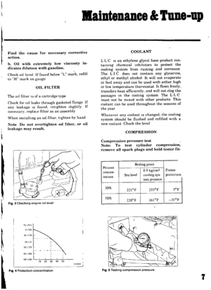 9
9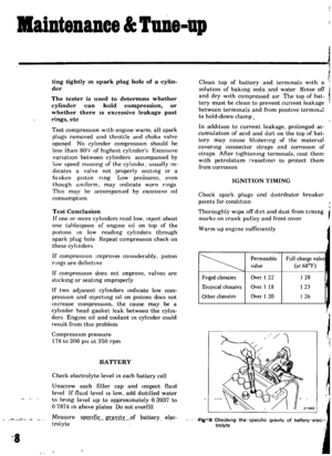 10
10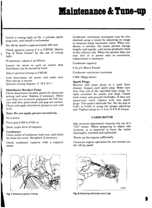 11
11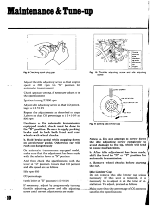 12
12 13
13 14
14 15
15 16
16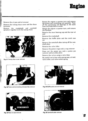 17
17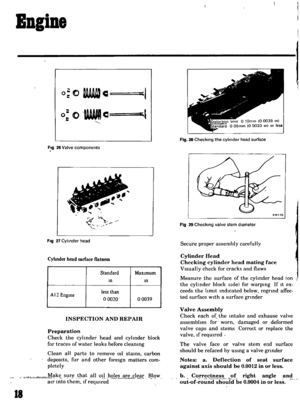 18
18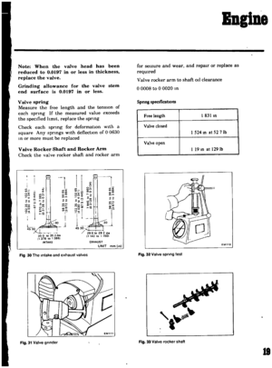 19
19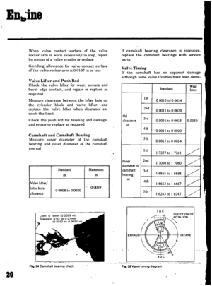 20
20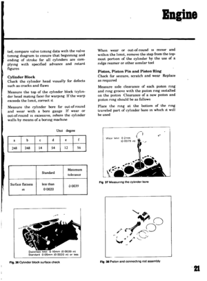 21
21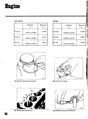 22
22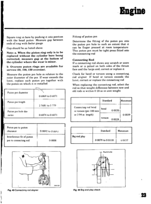 23
23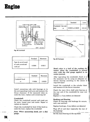 24
24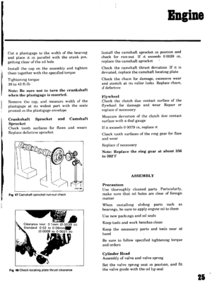 25
25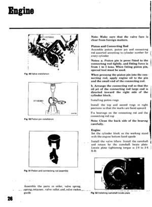 26
26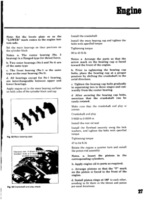 27
27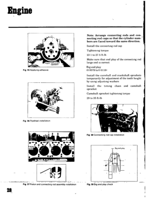 28
28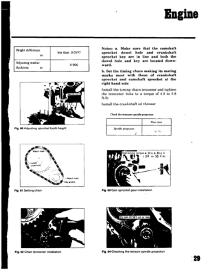 29
29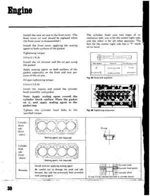 30
30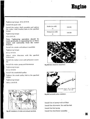 31
31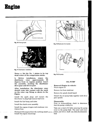 32
32 33
33 34
34 35
35 36
36 37
37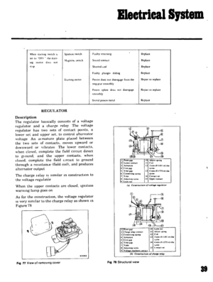 38
38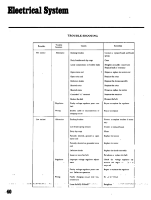 39
39 40
40 41
41 42
42 43
43 44
44 45
45 46
46 47
47 48
48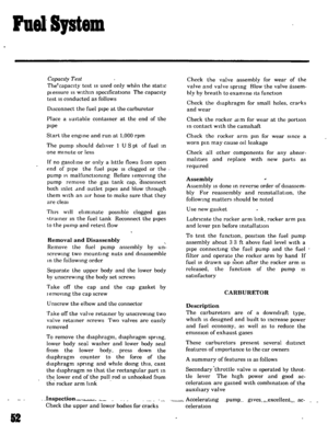 49
49 50
50 51
51 52
52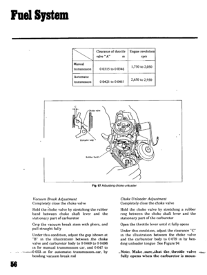 53
53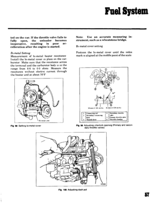 54
54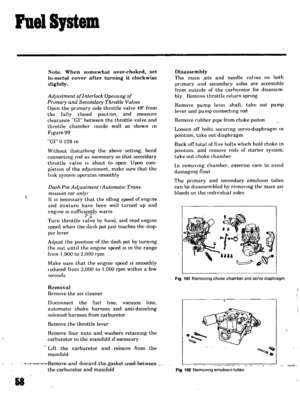 55
55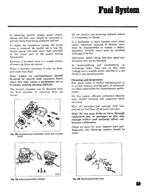 56
56 57
57 58
58 59
59 60
60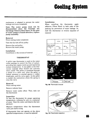 61
61 62
62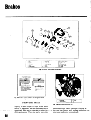 63
63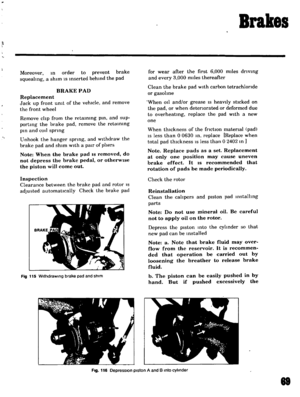 64
64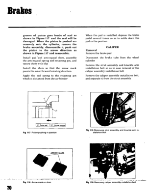 65
65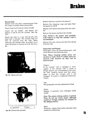 66
66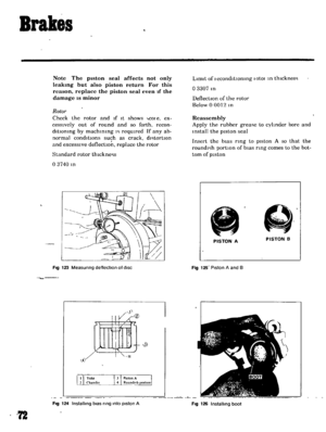 67
67 68
68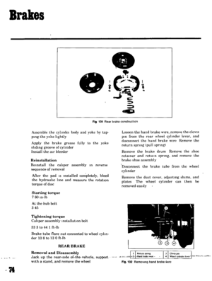 69
69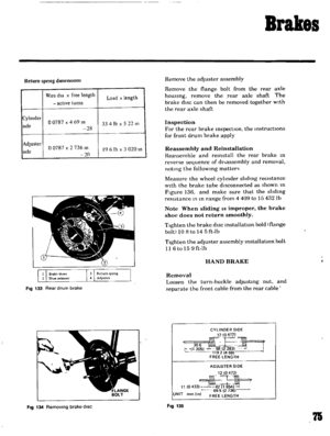 70
70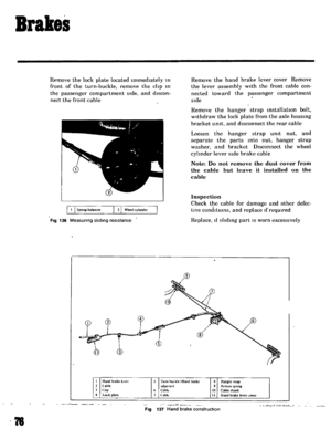 71
71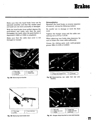 72
72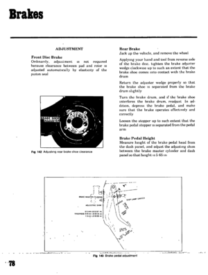 73
73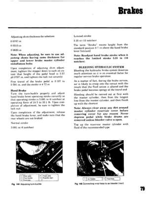 74
74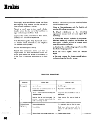 75
75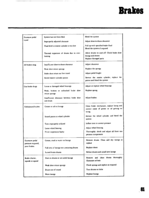 76
76 77
77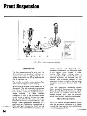 78
78 79
79 80
80 81
81 82
82 83
83 84
84 85
85 86
86 87
87 88
88 89
89 90
90 91
91 92
92 93
93 94
94 95
95 96
96 97
97 98
98 99
99 100
100 101
101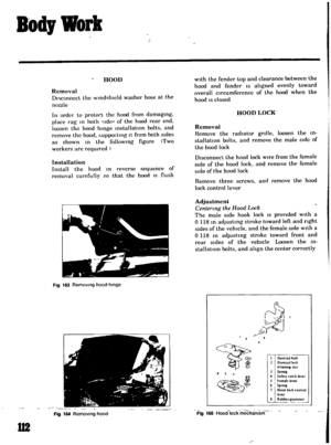 102
102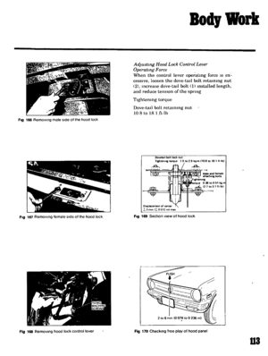 103
103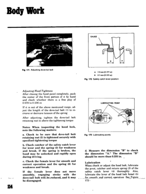 104
104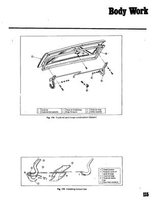 105
105 106
106 107
107 108
108 109
109 110
110 111
111 112
112 113
113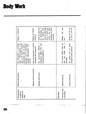 114
114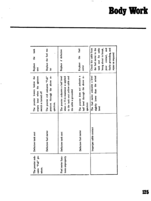 115
115 116
116 117
117 118
118 119
119 120
120 121
121 122
122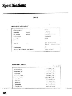 123
123 124
124 125
125 126
126 127
127 128
128 129
129 130
130 131
131 132
132 133
133 134
134 135
135
