Page 49 of 136

Fuel
Sptem
Capacity
Test
The
capaclty
test
IS
used
only
when
the
statIc
plessure
IS
wlthm
specIficatIOns
The
capacity
test
IS
conducted
as
follows
Disconnect
the
fuel
p1pe
at
the
carburetor
Place
a
bUltable
contamer
at
the
end
of
the
pIpe
Start
the
engme
and
run
at
1
000
rpm
The
pump
should
delIver
1
US
pt
of
fuel
In
one
mmute
or
less
If
no
gasolme
or
only
a
lIttle
flows
flOm
open
end
of
pIpe
the
fuel
pIpe
IS
clogged
or
the
pump
I
malfunctlOntng
Before
removing
the
pump
remove
the
gas
tank
cap
dIsconnect
both
Inlet
dnd
outlet
pIpes
and
blow
through
them
wIth
an
aIr
hose
to
make
sure
that
they
are
clear
Thl
wIll
elImmate
pOSSible
clogged
gas
tramer
In
the
fuel
tank
Reconnect
the
pIpes
to
the
pump
and
rete
t
flow
Removal
and
DisassenbIy
Remove
the
fuel
pump
assembly
by
un
screwmg
two
mounting
nuts
and
dIsassemble
In
the
follOWing
order
Separate
the
upper
body
and
the
lower
body
by
unscrewmg
the
body
set
screws
Take
off
the
cap
and
the
cap
gasket
by
I
emOVIng
the
cap
screw
Unscrew
the
elbow
and
the
connector
Take
off
the
valve
retainer
by
unscrewmg
two
valve
retamer
screws
Two
valves
are
eaSIly
removed
To
remove
the
diaphragm
diaphragm
sprmg
lower
body
seal
washer
and
lower
body
seal
from
the
lower
body
press
down
the
dIaphragm
counter
to
the
force
of
the
dIaphragm
spring
and
while
dOIng
thIS
cant
the
dIaphragm
so
that
the
rectangular
part
m
the
lower
end
of
the
pull
rod
IS
unhooked
from
the
rocker
arm
lInk
Inspection
Check
the
upper
and
lower
bodIes
for
cracks
2
Check
the
valve
assembly
for
wear
of
the
valve
and
valve
sprmg
Blow
the
valve
assem
bly
by
breath
to
examme
ItS
functIOn
Check
the
dIaphragm
for
small
holes
cral
ks
and
wear
Check
the
rocker
dl
m
for
wear
at
the
portIOn
In
contact
With
the
camshaft
Check
the
rocker
arm
pin
for
wear
since
a
worn
pm
may
cause
011
leakage
Check
all
other
components
for
any
abnor
mahtIes
and
replace
With
new
parts
as
requIred
Assembly
Assembly
IS
done
In
reverse
order
of
disassem
bly
For
reassembly
and
remstallatlOn
the
followmg
matters
should
be
noted
Use
new
gasket
Lubricate
the
rocker
arm
link
rocker
arm
pm
and
lever
pm
before
mstallatlOlI
To
test
the
functIOn
poSItIOn
the
fuel
pump
assembly
about
33ft
above
fuel
level
WIth
a
pipe
connecting
the
fuel
pump
and
the
fuel
filter
and
operate
the
rocker
arm
by
hand
If
fuel
IS
drawn
up
soon
after
the
rocker
arm
IS
released
the
functIOn
of
the
pump
IS
satIsfactory
CARBURETOR
Description
The
carburetors
are
of
a
downdraft
type
whIch
IS
deSIgned
and
bUIlt
to
Increase
power
and
fuel
economy
as
well
as
to
reduce
the
em1SSlon
of
exhaust
gases
These
carburetors
present
several
dIstinct
features
of
Importance
to
the
car
owners
A
summary
of
features
IS
as
follows
Secondary
throttle
valve
IS
operated
by
throt
tie
lever
The
hIgh
power
and
good
ac
celeratIon
are
gained
With
combmatlOn
of
the
auxlhary
valve
Acceleratmg
pump
glves
excellent
ac
celeratIon
Page 50 of 136

Fuel
Sptem
The
power
valve
mechanIsm
IS
of
a
vacuum
actuated
boost
type
and
Improves
hIgh
speed
drivIng
The
throttle
opener
control
system
Incor
porates
a
servo
diaphragm
The
servo
dIaphragm
helps
open
the
throttle
valve
at
a
decreasIng
speed
so
as
to
reduce
the
emISSIOn
of
hydrocarbons
to
a
minImum
An
antI
dlesehng
olen01d
IS
used
as
a
means
of
preventIng
dlesehng
When
the
IgnItIOn
key
IS
turned
ofT
the
fuel
passage
Involved
In
the
slow
system
IS
closed
and
the
fuel
supply
IS
shut
down
completely
In
the
chok
mechanIsm
an
electric
automatIc
choke
IS
used
to
automatically
con
trol
the
choke
valve
operatIOn
durIng
the
war
m
up
of
the
engIne
The
carburetor
for
automatic
transmiSSIOn
IS
eqUIpped
WIth
so
called
dash
pot
that
IS
It
makes
smooth
deceleratIng
WIthout
engIne
stall
at
any
operatIng
conditIOn
These
carburetors
are
qUIte
SImIlar
In
ap
pearance
as
explaIned
above
except
the
dash
pot
for
the
automatIc
transmISSion
model
Adjustment
Idhng
Adjustment
Idle
mixture
adjustment
requIres
the
use
of
a
CO
meter
When
prepatlng
to
adjust
Idle
mIxture
It
IS
essentIal
to
have
the
meter
thoroughly
warmed
and
cahbrated
Warm
up
the
engIne
suffiCiently
ContInue
engme
operatIOn
for
one
mmute
un
der
ldhng
speed
Adjust
throttle
adjustIng
screw
so
that
engme
speed
IS
800
rpm
m
N
pos1tIon
for
automatic
transmiSSIOn
Check
IgmtlOn
tl
If
necessary
adjust
It
to
the
speCificatIOns
IgnItIOn
tImlo
800
rpm
Adjust
Idle
adJustmg
screw
so
that
CO
percen
tage
IS
1
5
0
50
at
800
ns
a
On
automatIc
transmiSSIOn
eqUipped
model
check
must
be
done
In
the
D
poSItIon
Be
sure
to
apply
parkmg
brake
and
to
lock
both
front
and
rear
wheels
With
wheel
chocks
b
Hold
brake
pedal
while
steppIng
down
on
accelerator
pedal
OtherWise
car
Will
rush
out
dangerously
On
automatIc
transmiSSIOn
eqUIpped
model
make
sure
that
the
adjustment
has
been
made
With
the
selector
lever
In
N
posItIon
And
then
check
the
specificatIOns
With
the
lever
In
D
pOSitIOn
Insure
that
CO
percent
and
Idle
speed
are
as
follows
Idle
rpm
650
for
Manual
transmISSion
for
Automatic
transmISSion
Fig
91
External
view
of
carburetor
3
Page 51 of 136

ruel
Sptem
CO
percentage
with
lever
In
D
posltton
15
050
If
necessary
adjust
by
progressively
turmng
throttle
adjustIng
screw
and
Idle
adJusttng
screw
unttl
correct
adjustments
are
made
Notes
a
Do
not
attempt
to
screw
down
the
Idle
adjusting
screw
completely
to
aVOid
damage
to
the
tip
which
will
tend
to
cause
malfunctions
b
After
idle
adjustment
has
been
made
shift
the
lever
to
UN
or
P
position
for
automatic
transmission
c
Remove
wheel
chocks
before
starting
the
car
Idle
Limiter
Cap
Do
not
remove
this
Idle
hmlter
cap
unless
nccesbary
If
this
Unit
IS
removed
It
IS
I
Throttle
adJu
tmg
suew
2
Idle
adJu
t
Ing
rcw
3
Idle
hmlter
p
4
Stopper
FIg
92
Throttle
adjusting
screw
and
Idle
adjusting
screw
rl1urdor
topper
Fig
93
Setting
Idle
limiter
cap
54
necessary
to
re
adJust
it
at
the
time
of
In
stallatIOn
To
adjust
proceed
as
follows
Make
sure
that
the
percentage
of
CO
contents
sattsfies
the
speClficattons
Install
idle
hmIter
cap
In
poSItIOn
makIng
sure
that
the
adjustIng
screw
can
further
turn
rotatIOn
In
the
CO
RICH
dIrectIOn
Fuel
Level
Adjustment
Turn
down
the
float
chamber
to
allow
the
float
comIng
Into
contact
WIth
the
needle
valve
and
measure
R
shown
In
Figure
91
When
the
H
IS
approximately
190
mm
0748
In
top
float
posltton
IS
correct
The
top
float
pOSitIOn
can
be
adjusted
by
bendIng
float
seat
Upon
completIOn
of
the
adjustment
check
fuel
level
WIth
the
attached
level
gauge
Adjust
bottom
float
posItion
so
that
clearance
h
between
the
float
seat
and
the
needle
valve
stem
IS
0
0512
to
00669
In
when
the
float
IS
fully
raIsed
Bend
the
float
stopper
properly
as
reqUIred
Fast
Idle
Adjustment
Remove
the
bl
metal
cover
Place
the
fast
Idle
arm
on
the
second
step
of
the
fast
idle
cam
Then
adjust
the
fast
Idle
ad
JustIng
screw
In
such
a
way
that
the
clearance
of
the
throttle
valve
shown
at
A
In
the
Illustratton
Will
be
the
speCificatIOns
See
Figure
92
IH
Float
Float
seat
3
noall
topper
4
Needle
alve
Fig
94
AdJusting
float
level
Page 52 of 136
Fuel
Sptem
FIg
95
Adjusting
fast
d
Ie
B
Choke
val
I
V
uvm
b
k
stem
Vacuum
break
stew
Fig
96
Adjusting
vacuum
break
1
Page 53 of 136

ruel
Sptem
Clearance
of
throttle
Engme
revolutIon
valve
A
ill
rpm
Manual
transmiSSIOn
o
0315
to
0
0346
I
750
to
2
050
Automatic
transmISSIOn
00421
to
0
0461
2
650
to
2
950
c
Rubbu
bJ
nd
Fig
97
Adjusting
choke
unloader
Vacuum
Break
Adjustment
Completely
close
the
choke
valve
Hold
the
choke
valve
by
stretching
the
rubber
band
between
choke
shaft
lever
and
the
btatlOnary
part
of
carburetor
Grip
the
vacuum
break
stem
with
phers
and
pull
straIght
fully
Under
thIS
condltton
adjust
the
gap
shown
at
8
In
the
111ustratlOnl
between
the
choke
valve
and
carburetor
body
to
00449
to
0
0496
In
for
manual
transmission
tar
and
0047
to
0
053
1n
for
automattc
transrnlsslOn
car
by
bending
vacuum
break
rod
51
Choke
Unloader
Adjustment
Completely
close
the
choke
valve
Hold
the
choke
valve
by
stretching
a
rubber
ring
between
the
choke
shaft
lever
and
the
stattonary
part
of
the
carburetor
Open
the
throttle
lever
unttllt
fully
opens
Under
thiS
condltton
adjust
the
clearance
C
In
the
IllustratIOn
between
the
choke
valve
and
the
carburetor
body
to
0
079
In
by
ben
ding
unloader
tongue
See
Figure
94
Note
Make
sure
that
the
throttle
valve
fully
opens
when
the
carburetor
is
moun
Page 54 of 136
Fuel
Sptem
ted
on
the
car
If
the
throttle
valve
fails
to
fully
open
the
unIoader
becomes
inoperative
resulting
in
poor
ac
celleration
after
the
engine
is
started
Note
Use
an
accurate
measuring
in
strument
such
as
a
wheatstone
bridge
B1
metal
cover
settmg
BL
metal
Settmg
Mea
urement
of
bl
metal
heater
resistance
Install
the
bl
metal
cover
m
place
on
the
car
buretor
Make
sure
that
the
resIstance
across
the
termmal
and
the
carburetor
body
IS
m
the
range
from
8
6
to
0
0
ohms
Measure
the
resIstance
without
electnc
current
through
the
heater
and
at
about
70
F
Postllon
the
bl
metal
cover
until
the
mdex
mark
1S
altgned
at
the
middle
pomt
of
the
scale
26
mm
I
024
m
dlJ
30
m
1
181
In
dlJ
Connectml
rod
Secondary
COnnCl
lms
lever
Throltle
lever
4
Secondary
throttle
vaJve
5
Pnmary
throttle
valve
6
Throttle
chamber
Fig
98
Settmg
bl
metal
cover
Fig
99
AdJustmg
mterlock
opening
Pnmary
and
secon
dary
throttle
valves
Fig
100
AdJustmg
dash
pot
17
Page 55 of 136

ruel
S
stem
Note
When
somewhat
over
choked
set
bl
metal
cover
after
turning
it
clockwise
slightly
Adjustment
oflnterlock
Opelntng
of
Pnmary
and
Secondary
Throttle
Values
Open
the
pnmary
Side
throttle
valve
48
from
the
fully
closed
positIOn
and
measure
clearance
GIn
between
the
throttle
valve
and
throttle
chamber
mSlde
wall
as
shown
m
Figure
99
GIn
0
228
m
WIthout
dlsturbmg
the
above
settmg
bend
connectmg
rod
as
necessary
so
that
secoridary
throttle
valve
IS
about
to
open
Upon
com
pletIOn
of
the
adjustment
make
sure
that
the
hnk
system
operates
smoothly
Dash
Pot
Adjustment
AutomatIC
Trans
mlsszon
car
only
It
IS
necessary
that
the
Idhng
speed
of
engme
and
mIxture
have
been
well
turned
up
and
engme
IS
suffiC1
n
y
warm
1
Turn
throttle
valve
by
hand
and
read
engme
speed
when
the
da
h
pot
Just
touches
the
stop
per
lever
Adjust
the
pOSitIOn
of
the
dash
pot
by
turnmg
the
nut
until
the
engine
speed
IS
In
the
range
from
1
900
to
2
000
rpm
Make
sure
that
the
engine
speed
IS
smoothly
leduced
from
3
000
to
1
000
rpm
within
a
few
econds
Removal
Remove
the
aIr
cleaner
DIsconnect
the
fuel
line
vacuum
line
automatic
choke
harness
and
antl
dlesehng
solenOId
harness
from
carburetor
Remove
the
throttle
lever
Remove
four
nuts
and
washers
retaining
the
carburetor
to
the
mamfold
If
necessary
LIft
the
carburetor
and
remove
from
the
mamfold
Remove
and
dlscard
the
gasketcused
between
the
carburetor
and
mamfold
8
Disassembly
The
main
Jets
and
needle
valves
on
both
primary
and
secondary
Sides
are
accessible
from
outSIde
of
the
carburetor
for
disassem
bly
Remove
throttle
return
sprmg
Remove
pump
level
shaft
take
out
pump
lever
and
pump
connectmg
rod
Remove
rubber
pipe
from
choke
piston
Loosen
off
bolts
secutlng
servo
diaphragm
In
positIOn
take
out
dIaphragm
Back
off
total
of
five
bolts
which
hold
choke
In
posItion
and
remove
rods
of
starter
system
take
out
choke
chamber
In
removmg
chamber
exercise
care
to
aVOId
damaging
float
The
pnmary
and
secondary
emulsIOn
tubes
can
be
disassembled
by
removmg
the
main
air
bleeds
on
the
indiVidual
SIdes
UII
ij
Fig
101
Removmg
choke
chamber
and
servo
diaphragm
o
llQt
o
Fig
102
Removmg
emulsion
tubes
Page 56 of 136

Fuel
Sptem
In
removIng
Injector
weight
piston
return
sptlng
and
ball
care
should
be
exercIsed
to
prevent
them
from
beIng
scattered
and
lost
To
check
the
accelerator
pump
the
pump
cover
IS
removed
Be
careful
not
to
lose
the
return
spring
and
mlet
valve
bal
prOVided
at
the
lower
part
of
the
piston
dUring
dIsassembly
Removal
of
bl
metal
cover
IS
a
sImple
matter
of
removmg
three
set
screws
When
It
becomes
necessary
to
take
out
float
pull
shaft
from
float
Note
Under
no
C1rcumstances
should
bl
metaI
be
moved
with
excessive
force
Since
this
may
cause
a
permanent
set
In
b1
metal
making
starting
d1fficuIt
The
thlottle
chamber
can
be
detached
from
the
float
hamber
by
removmg
three
set
screws
Fig
103
Disassembling
accelerator
pump
and
bl
metal
cover
1
EC013
Fig
104
RemOVing
throttle
chamber
Do
not
remove
antl
dlesehng
solenOId
unless
It
IS
necessary
to
change
It
IS
preferable
to
leave
throttle
valve
mtact
unless
otherWise
reqUIred
If
throttle
valve
must
be
dIsassembled
to
remedy
a
defect
secondary
throttle
valve
must
be
Installed
wIth
gap
to
be
free
OtherWise
stable
Idlmg
and
slow
speed
per
formance
Will
not
be
obtamed
In
dlsassembhng
and
reassembhng
in
terlockIng
hnks
take
care
so
that
each
lInkage
has
a
smooth
action
and
that
It
IS
not
fitted
m
any
forced
posltton
Cleaning
and
Inspection
Dirt
gum
water
or
carbon
contammatIon
m
or
on
the
exterior
movmg
parts
of
carburetor
are
often
responsible
for
unsattsfactory
perfor
mance
For
thiS
reason
effiCient
carbureton
depends
upon
careful
cleamng
and
InspectIOn
whtle
servlcmg
Blow
all
passages
and
castmgs
wIth
com
pressed
aIr
and
blow
off
all
parts
unttl
dry
Note
Do
not
pass
drills
or
wires
through
calibrated
jets
or
passages
as
this
may
enlarge
orifice
and
seriously
affect
car
buretor
calibration
Check
all
parts
for
wear
Replace
worn
part
EspeCially
the
followmg
matters
should
he
noted
I
1
Q
o
Fig
105
RemOVing
throttle
valve
18
 1
1 2
2 3
3 4
4 5
5 6
6 7
7 8
8 9
9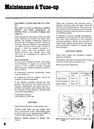 10
10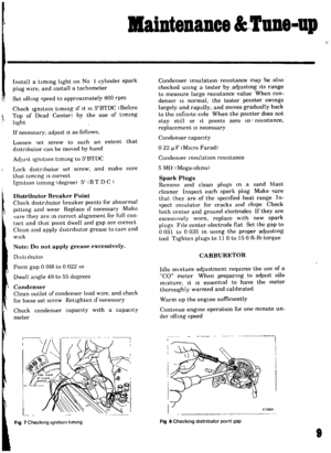 11
11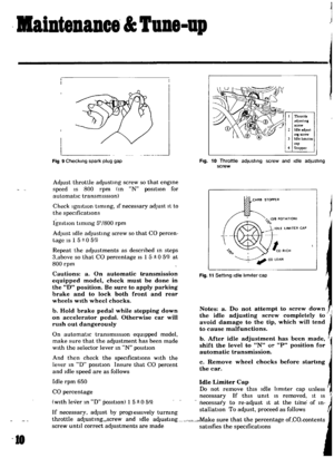 12
12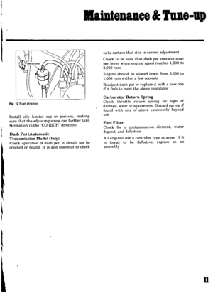 13
13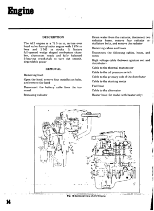 14
14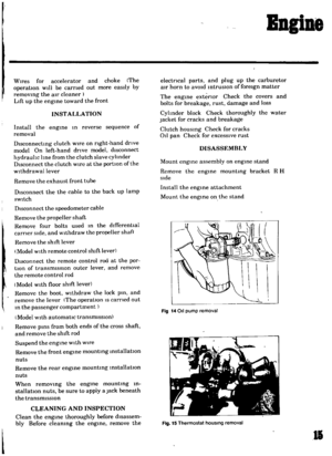 15
15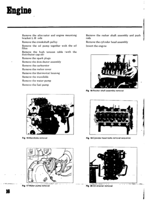 16
16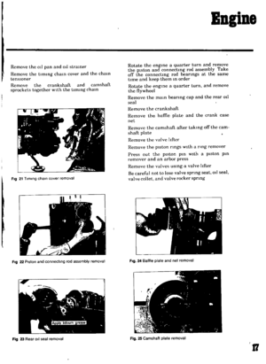 17
17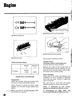 18
18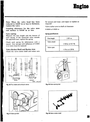 19
19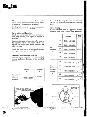 20
20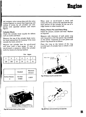 21
21 22
22 23
23 24
24 25
25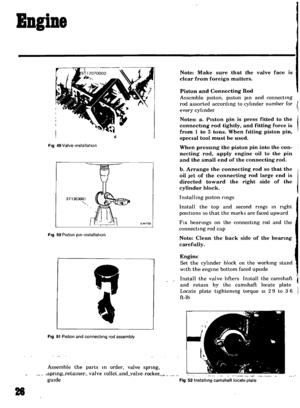 26
26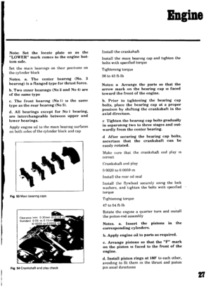 27
27 28
28 29
29 30
30 31
31 32
32 33
33 34
34 35
35 36
36 37
37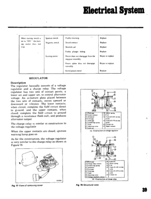 38
38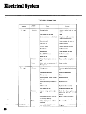 39
39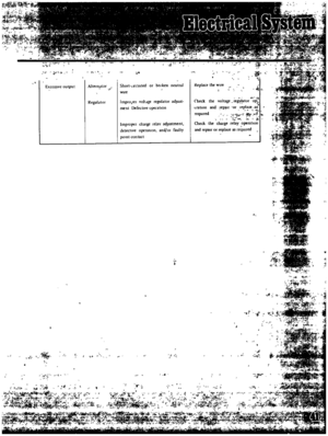 40
40 41
41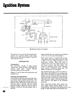 42
42 43
43 44
44 45
45 46
46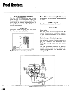 47
47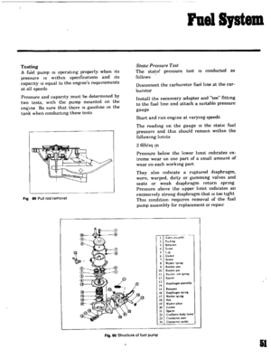 48
48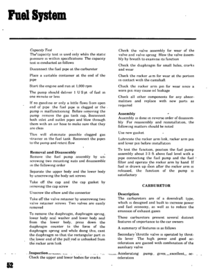 49
49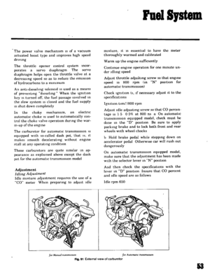 50
50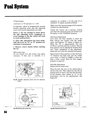 51
51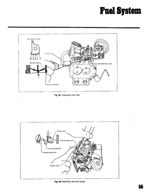 52
52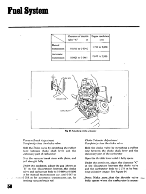 53
53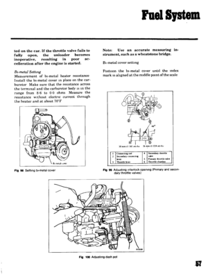 54
54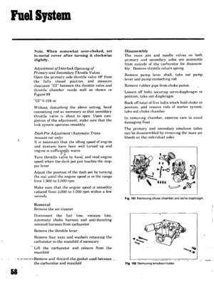 55
55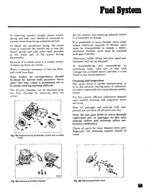 56
56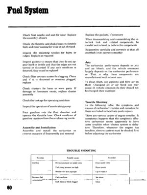 57
57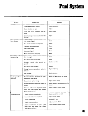 58
58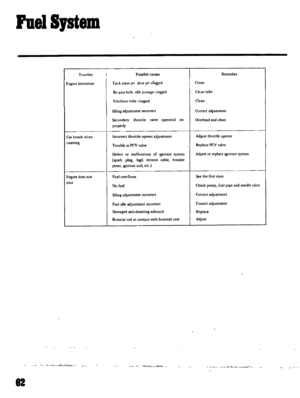 59
59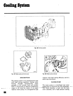 60
60 61
61 62
62 63
63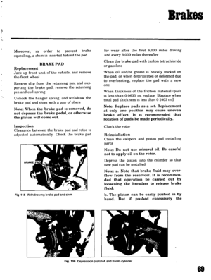 64
64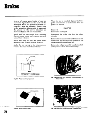 65
65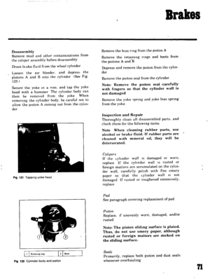 66
66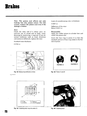 67
67 68
68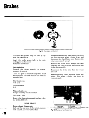 69
69 70
70 71
71 72
72 73
73 74
74 75
75 76
76 77
77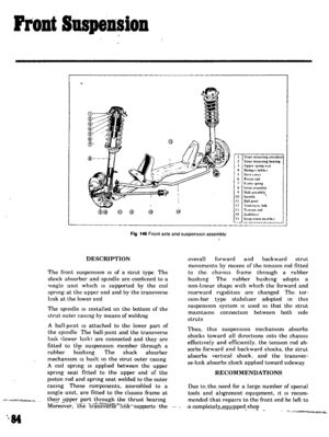 78
78 79
79 80
80 81
81 82
82 83
83 84
84 85
85 86
86 87
87 88
88 89
89 90
90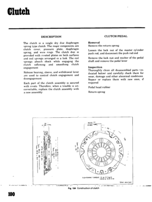 91
91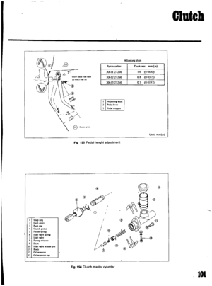 92
92 93
93 94
94 95
95 96
96 97
97 98
98 99
99 100
100 101
101 102
102 103
103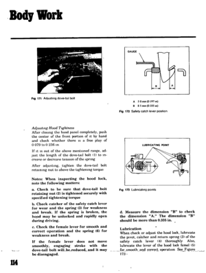 104
104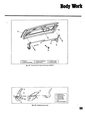 105
105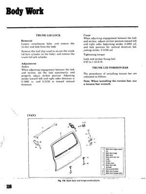 106
106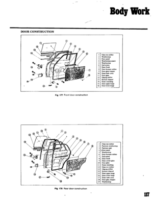 107
107 108
108 109
109 110
110 111
111 112
112 113
113 114
114 115
115 116
116 117
117 118
118 119
119 120
120 121
121 122
122 123
123 124
124 125
125 126
126 127
127 128
128 129
129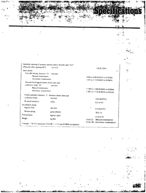 130
130 131
131 132
132 133
133 134
134 135
135
