1968 DATSUN 510 brake
[x] Cancel search: brakePage 23 of 252
18
CHAP1
lER
THlREE
c
c
c
ce
J
1
Ii
j
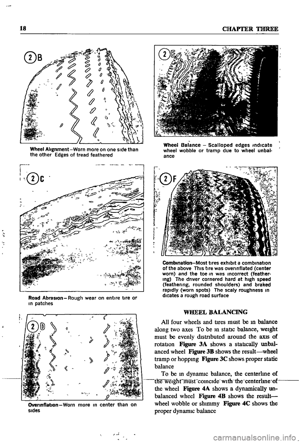
Wheel
Alignment
Worn
more
on
one
sIde
than
the
other
Edges
of
tread
feathered
r
I
0c
l
Road
Abrasion
Rough
wear
on
entire
tire
or
In
patches
t
y
1
OverInflabon
Worn
more
In
center
than
on
sides
Wheel
Balance
Scalloped
edges
indicate
wheel
wobble
or
tramp
due
to
wheel
unbal
ance
f
Q
F
r
r
r
f
i
m
i
O
2
7
iK
J
1
J
i
i
5J
CombInation
Most
tIres
exhibit
a
combination
of
the
above
This
tIre
was
overinflated
center
worn
and
the
toe
In
was
Incorrect
feather
Ing
The
driver
cornered
hard
at
high
speed
feathering
rounded
shoulders
and
braked
rapidly
worn
spots
The
scaly
roughness
In
dlcates
a
rough
road
surface
WHEEL
BALANCING
All
four
wheels
and
tIres
must
be
ill
balance
along
two
axes
To
be
ill
statIc
balance
weight
must
be
evenly
dlstnbuted
around
the
llXlS
of
rotatIon
Figure
3A
shows
a
statIcally
unbal
anced
wheel
Figure
3B
shows
the
result
wheel
tramp
or
hoppmg
Figure
3C
shows
proper
static
balance
To
be
ill
dynamiC
balance
the
centerhne
of
die
welghtmusCcomclde
with
the
centerhne
of
the
wheel
Figure
4A
shows
a
dynamically
un
balanced
wheel
Figure
4B
shows
the
result
wheel
wobble
or
shmuny
Figure
4C
shows
the
proper
dynannc
balance
Page 31 of 252
26
CHAPTER
FOUR
2
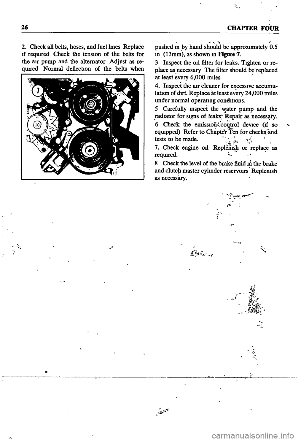
Check
all
belts
hoses
and
fuellmes
Replace
If
reqUIred
Check
the
tensIon
of
the
belts
for
the
au
pump
and
the
alternator
Adjust
as
re
qUIred
Normal
deflection
of
the
belts
when
pushed
m
by
hand
should
be
approXImately
0
5
m
13mm
as
shown
m
Figure
7
3
Inspect
the
011
filter
for
leaks
TIghten
or
re
place
as
necessary
The
filter
should
replaced
at
least
every
6
000
mIles
4
Inspect
the
lIlr
cleaner
for
excessIve
accumu
latIon
of
dIrt
Replace
at
least
every
24
000
miles
under
normal
operatmg
cornhtIons
5
Carefully
mspect
the
water
pump
and
the
radIator
for
SIgnS
of
leaks
Repair
as
necessl
i
y
6
Check
the
emissIoo
control
deVice
If
so
eqwpped
Refer
to
Chapter
Ten
for
checks
and
tests
to
be
made
c
1
7
Check
engine
oIl
Replems
9
or
replace
as
reqUIred
8
Check
the
level
of
the
brake
fluid
m
the
brake
and
clutcJ1
master
cylmder
reservOirs
ReplenISh
as
necessary
ii
t
d
fl
tlJ
l
Page 44 of 252
ENGINE
39
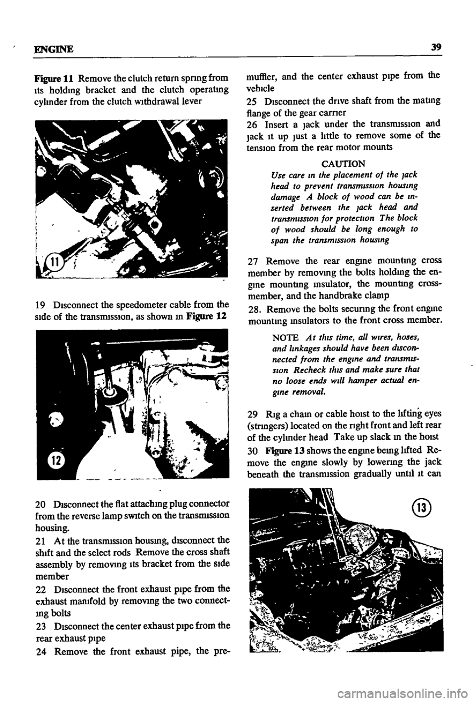
Figure
11
Remove
the
clutch
return
spnng
from
Its
holdmg
bracket
and
the
clutch
operatmg
cylmder
from
the
clutch
withdrawal
lever
19
Disconnect
the
speedometer
cable
from
the
side
of
the
transnnsslOn
as
shown
m
Figure
12
20
Disconnect
the
flat
attachmg
plug
connector
from
the
reverse
lamp
sWitch
on
the
translDlSSlon
housing
21
At
the
transnnsslOn
housmg
disconnect
the
shIft
and
the
select
rods
Remove
the
cross
shaft
assembly
by
remOVIng
Its
bracket
from
the
Side
member
22
DISconnect
the
front
exhaust
pipe
from
the
exhaust
manIfold
by
remoVing
the
two
connect
mg
bolts
23
Disconnect
the
center
exhaust
pipe
from
the
rear
exhaust
pipe
24
Remove
the
front
exhaust
pipe
the
pre
muffler
and
the
center
exhaust
pipe
from
the
vehicle
25
Disconnect
the
dnve
shaft
from
the
matIng
flange
of
the
gear
carner
26
Insert
a
Jack
under
the
transmiSSIOn
and
jack
It
up
Just
a
little
to
remove
some
of
the
tension
from
the
rear
motor
mounts
CAUTION
Use
care
m
the
placement
of
the
lack
head
to
prevent
transmiSSIOn
housmg
damage
A
block
of
wood
can
be
m
serted
between
the
Jack
head
and
transmISSIOn
for
protection
The
block
of
wood
should
be
long
enough
to
span
the
transmiSSion
housmg
27
Remove
the
rear
engine
mountIng
cross
member
by
remoVing
the
bolts
holdmg
the
en
gine
mountIng
msulator
the
mountIng
cross
member
and
the
handbrake
clamp
28
Remove
the
bolts
secunng
the
front
engine
mountmg
msulators
to
the
front
cross
member
NOTE
At
thiS
time
all
Wires
hoses
and
lmkages
should
have
been
dIScon
nected
from
the
engme
and
transmIS
sIOn
Recheck
thiS
and
make
sure
that
no
loose
ends
Will
hamper
actual
en
gme
removal
29
RIg
a
cham
or
cable
hOist
to
the
lifting
eyes
stnngers
located
on
the
nght
front
and
left
rear
of
the
cylmder
head
Take
up
slack
m
the
hOist
30
Figure
13
shows
the
engme
bemg
lifted
Re
move
the
engine
slowly
by
lowenng
the
jack
beneath
the
transnnssion
gradually
until
It
can
@
Page 65 of 252
60
SIX
Table
1
ENGINE
SERVICE
DATA
AND
SPECIFICATIONS
GENERAL
SPECIFICATIONS
Cylinder
Arrangement
DIsplacement
Bore
and
Stroke
Valve
Arrangement
MaxImum
Brake
Horsepower
MaxImum
Gross
Torque
Firing
Order
Engme
dle
Smgle
POint
Dual
Pomt
CompressIon
RatIo
Engme
Idle
Mamfold
at
Idle
rpm
011
Pressure
hot
@
2
000
rpm
i
TIGHTENING
TORQUE
ft
Ib
kg
m
Cylinder
Head
Bolts
1st
turn
2nd
turn
Flywheel
Flxmg
Bolts
M
In
Beanng
Cap
Bolts
Camshaft
Gear
Bolt
I
011
Pan
1
1
fF
I
011
Pump
QII
Stramer
F
I
Crank
Pulley
Bolt
SPECIFICATIONS
In
mm
Valve
Mechamsm
Valve
Clearance
Hot
Valve
Clearance
Cold
Valve
Head
DIameter
Intake
Valve
Head
DIameter
Exhaust
Valve
Stem
DIameter
Intake
Valve
Stem
DIameter
Exhaust
Valve
Length
Intake
Valve
Length
Exhaust
Valve
LIft
Valve
Spring
Free
Length
Outer
Valve
Sprmg
Free
Length
Inner
Vaiv
Spnng
Loaded
Length
Outer
Valve
Spring
Loaded
Length
Inner
Valve
Sprmg
Assembllld
HeIght
Outer
Valve
Spnng
Assembled
Helght
Inner
Valve
Spnng
Effective
Turns
Outer
Valve
Sprmg
EffectIve
Turns
Inner
Valve
GUIde
Length
Intake
Valve
GUIde
Length
Exhaust
Valve
GUIde
HeIght
from
Head
Surface
Valve
GUIde
Inner
DIameter
Intake
Valve
GUIde
Inner
DIameter
Exhaust
Va
Ive
GUIde
Outer
Dlam
eter
Intake
Valve
GUIde
Outer
DIameter
Exhaust
Valve
GUIde
to
Stem
Clearance
Intake
Valve
GUIde
to
Stem
Clearance
Exhaust
Valve
eat
W
dth
Intake
Valve
SEtat
WIdth
Exhaust
4
m
Ilnil
97
3
cu
m
1595cc
3
2677
x
2
9016
In
83
x
73
7mm
Overhead
Camshaft
96
@
5
600
rpm
110
ft
Ib
13
8
kg
m
@
3
600
rpm
1
3
4
2
r
600
rpm
700
pm
85
1
i7
7
In
Hg
450mm
Hg
54
to
60
Ib
m
2
3
8
tQ
4
2
Iig
cm
325
4
5
39
8
5
5
68
No
75
9
9
50
to
1039
325
to
39
8
4
5
to
5
5
362
to
43
4
50
to
60
2
9
to
5
1
0
4
to
0
7
108
to
15
2
1
5
to
2
1
58t087
08to
12
1157
to
130
1
160
to
180
o
118
0
30
o
0C
98
0
25
1
50
38
0
1
30
33
0
031
80
031
80
456
1159
4
57
116
O
03937
100
2
05
52
0
1
77
44
96
1
21
@
1054
Ib
3
07
@
47
8
kg
o
96
@
56
Ib
24
5
@
25
5
kg
1
53
@
63
9
Ib
38
9
@
29
0
kg
1
38
@
27
1
Ib
35
@
123
kg
45
I
55
2
32
59
0
2
32
59
0
0409
to
0
417
104
to
106
0315
to
03154
80
to
8018
0315
to
03154
80
to
8
Oi8
04718
to
04723
11
985
to
11
996
04718
to
04723
11
985
to
11
996
00006
to
00018
0
015
to
0
045
00016
to
00028
0040
to
0070
o
055
to
0
071
1
4
to
1
8
0063
to
0079
1
6
to
20
Page 135 of 252
130
CHAPTER
ELEVEN
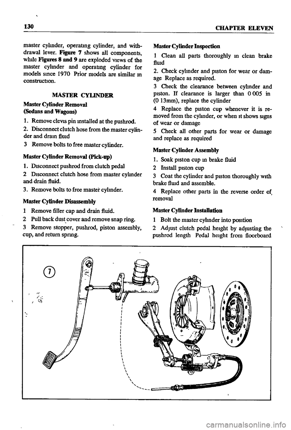
master
cylInder
operatlng
cylinder
and
with
drawal
lever
Figure
7
shows
all
components
whlle
Figures
8
and
9
are
exploded
VIews
of
the
master
cylmder
and
operatIng
cylinder
for
models
smce
1970
Prior
models
are
similar
In
construction
MASTER
CYLINDER
Master
Cylinder
Removal
Sedans
and
Wagons
1
Remove
cleVIS
pin
mstalled
at
the
pushrod
2
Disconnect
clutch
hose
from
the
master
cylin
der
and
dram
flwd
3
Remove
bolts
to
free
master
cylinder
Master
Cylinder
Removal
Pick
up
1
DIsconnect
pushrod
from
clutch
pedal
2
DIsconnect
clutch
hose
from
master
cylInder
and
drain
fluid
3
Remove
bolts
to
free
master
cylInder
Master
Cylinder
Disassembly
1
Remove
filler
cap
and
drain
fluid
2
Pull
back
dust
cover
and
remove
snap
ring
3
Remove
stopper
pushrod
piston
assembly
cup
and
return
spnng
CD
i
Master
Cylinder
Inspection
1
Clean
all
parts
thoroughly
In
clean
brake
flwd
2
Check
cylInder
and
pISton
for
wear
or
dam
age
Replace
as
required
3
Check
the
clearance
between
cylInder
and
pIston
If
clearance
is
larger
than
0
005
in
0
13mm
replace
the
cylinder
4
Replace
the
pISton
cup
whenever
it
is
re
moved
from
the
cylInder
or
when
It
shows
SIgnS
of
wear
or
damage
5
Check
all
other
parts
for
wear
or
damage
and
replace
as
required
Master
Cylinder
Assembly
1
Soak
piston
cup
m
brake
fluid
2
Install
pIston
cup
3
Coat
the
cylinder
and
pIston
thoroughly
WIth
brake
flwd
and
assemble
4
Replace
other
parts
in
the
reverse
order
of
removal
Master
Cylinder
Installation
1
Bolt
the
master
cylInder
into
pOSItion
2
Adjust
clutch
pedal
heIght
by
adjusting
the
pushrod
length
Pedal
heIght
from
floorboard
Page 138 of 252
CLUTCH
TRANSMISSION
AND
DRlVESIIAFI
133
C
8
Q@J
@
C
Operating
Cylinder
Reassembly
1
Soak
pISton
cup
m
brake
flUid
and
Install
It
In
the
same
pOSitIOn
as
before
removal
2
Apply
brake
flUid
to
the
cylInder
and
pIston
before
mstalImg
piston
3
Replace
all
parts
m
the
reverse
order
of
removal
Operating
Cylinder
Installation
1
RemstallatIon
IS
the
reverse
of
removal
2
Bleed
aIr
from
the
hydraulIc
system
3
Adjust
the
pushrod
so
that
withdrawal
lever
end
play
IS
0
0787
to
0
1181
In
2
0
to
3
Omm
Procedures
for
the
adjustment
are
given
below
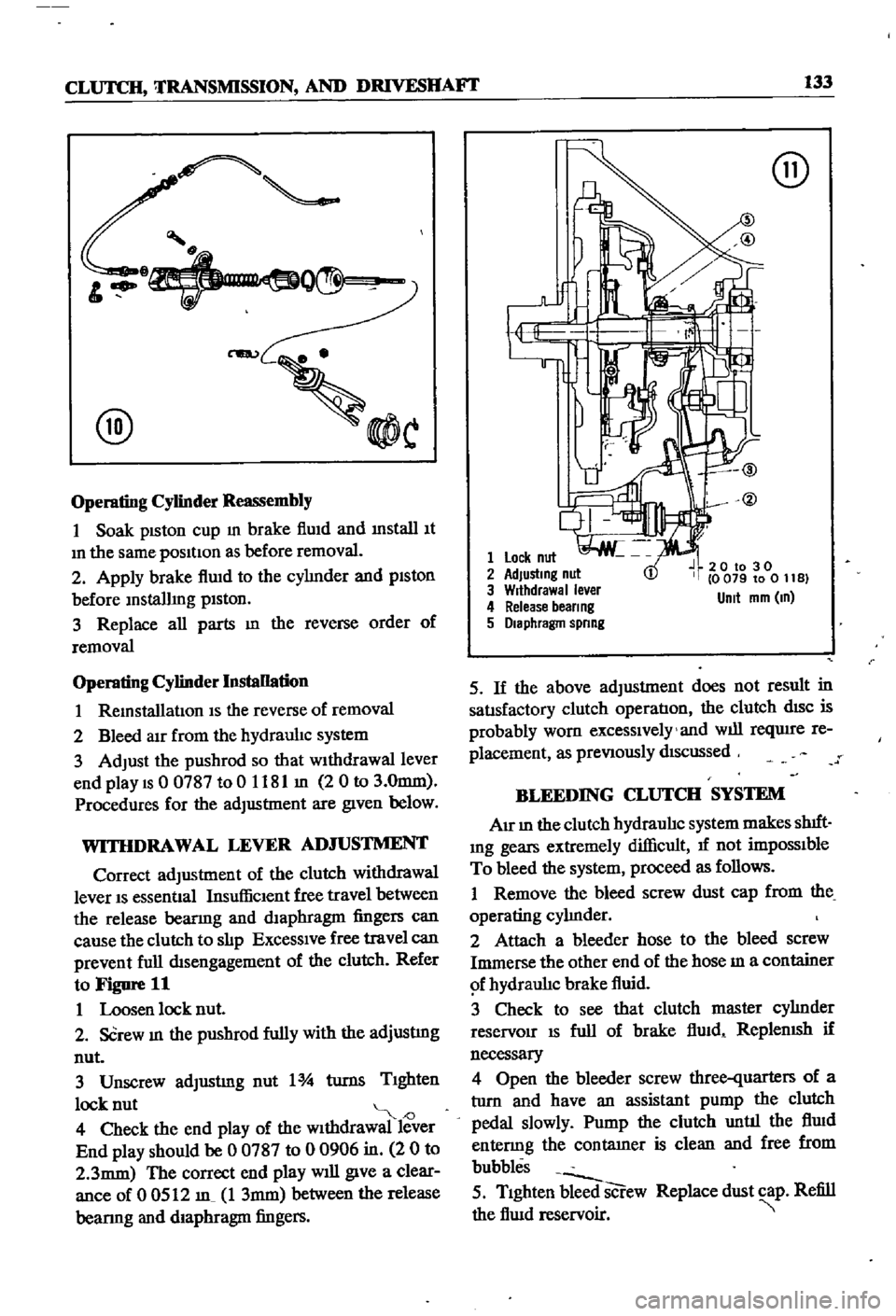
WITHDRAWAL
LEVER
AD
JUSTMENT
Correct
adjustment
of
the
clutch
withdrawal
lever
IS
essentIal
InsufficIent
free
travel
between
the
release
bearmg
and
dIaphragm
fingers
can
cause
the
clutch
to
slIp
ExceSSIve
free
travel
can
prevent
full
dISengagement
of
the
clutch
Refer
to
Figure
11
1
Loosen
lock
nut
2
SCrew
In
the
pushrod
fully
with
the
adjustmg
nut
3
Unscrew
adJustmg
nut
1
turns
TIghten
lock
nut
J
4
Check
the
end
play
of
the
wIthdrawal
lever
End
play
should
be
0
0787
to
0
0906
in
2
0
to
2
3mm
The
correct
end
play
will
give
a
clear
ance
of
0
0512
m
1
3mm
between
the
release
bearmg
and
diaphragm
fingers
@
1
Lock
nut
2
AdJustmg
nut
3
Wrthdrawal
ever
4
Release
beer
ng
5
Diaphragm
spnng
20
to
30
0
079
to
0
11
B
Unit
mm
m
5
If
the
above
adjustment
does
not
result
in
satIsfactory
clutch
operatIon
the
clutch
dISC
is
probably
worn
excessIvely
and
will
reqUire
re
placement
as
preVIously
dIScussed
BLEEDING
CLUTCH
SYSTEM
AIr
In
the
clutch
hydraulIc
system
makes
shIft
Ing
gears
extremely
difficult
1f
not
impOSSIble
To
bleed
the
system
proceed
as
follows
1
Remove
the
bleed
screw
dust
cap
from
the
operating
cylInder
2
Attach
a
bleeder
hose
to
the
bleed
screw
Immerse
the
other
end
of
the
hose
m
a
container
f
hydraulIc
brake
fluid
3
Check
to
see
that
clutch
master
cylInder
reservoir
IS
full
of
brake
flUid
ReplenISh
if
necessary
4
Open
the
bleeder
screw
three
quarters
of
a
tlIrn
and
have
an
assistant
pump
the
clutch
pedal
slowly
Pump
the
clutch
until
the
flUid
entenng
the
contatner
is
clean
and
free
from
bubbles
5
TIghten
bleed
screw
Replace
dust
cap
Refill
the
flUid
reservoir
Page 141 of 252
136
CHAPTER
ELEVEN
5
DIsconnect
and
remove
starter
motor
from
flywheel
housmg
as
descnbe4
In
Chapter
NIne
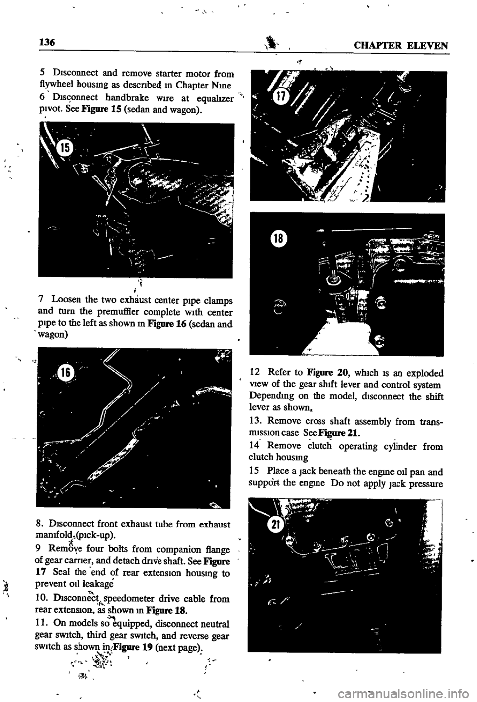
6
Dls
onnect
handbrake
WIre
at
equalIzer
pIVOt
See
Figure
15
sedan
and
wagon
I
j
7
Loosen
the
two
exhaust
center
p1pe
clamps
and
turn
the
premuffier
complete
With
center
pIpe
to
the
left
as
shown
m
FJgure
16
sedan
and
wagon
f
W
y
I
0
Y
h
0
ilo
8
DIsconnect
front
exhaust
tube
from
exhaust
man1fold
pICk
up
9
Rem
ye
four
bolts
from
companion
flange
of
gear
carner
and
detach
dnve
shaft
See
Figure
17
Seal
the
end
of
rear
extensIon
housmg
to
prevent
011
leakage
1
0
Dlsconn
i
gpeedometer
drive
cable
from
rear
extensIOn
as
shown
In
Figure
18
11
On
models
s
quipped
disconnect
neutral
gear
sWitch
third
gear
sWitch
and
reverse
gear
sWItch
as
shown
in
Figure
19
next
page
f
t
iT
l
t
t
W
12
Refer
to
Figure
20
whIch
IS
an
exploded
View
of
the
gear
shIft
lever
and
control
system
DependIng
on
the
model
dISconnect
the
shift
lever
as
shown
13
Remove
cross
shaft
assembly
from
trans
rmsslOn
case
See
Figure
21
14
Remove
clutch
operating
cylinder
from
clutch
housmg
15
Place
a
Jack
beneath
the
engme
011
pan
and
SuppOFt
the
engme
Do
not
apply
Jack
pressure
Page 149 of 252
144
CHAPTER
ELEVEN
TAANSMISSlON
SERVICE
DATA
AND
SPECIRCATIONS
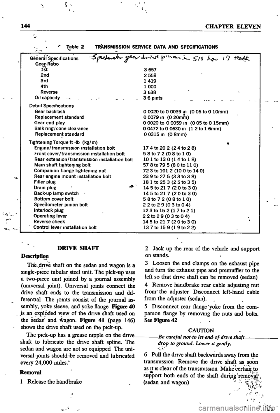
Table
2
r
General
SpecificatIOns
Gear
Ratlo
1st
2nd
3rd
4th
Reverse
011
capacity
Detail
SpeCIfications
Gear
backlash
Replacement
standard
Gear
end
play
Balk
ring
cone
clearance
Replacement
standard
5
tl
viV
t
O
5
0
If
3657
2558
1419
1000
3638
3
6
pints
Tightening
Torque
ft
Ib
kg
m
Engine
transmission
installation
bolt
Front
cover
transmission
installation
bolt
Rear
extensIon
transmIssion
installation
bolt
Main
shaft
tlghtel
lng
bolt
Companion
flange
tightening
nut
Rear
engine
mount
installation
bolt
Filler
plug
Drain
plug
Back
up
lamp
sWItch
Bottom
cover
bolt
Speedometer
pinion
bolt
Interlock
plug
Operating
lever
Reverse
check
Control
lever
installatIOn
bolt
00020
to
0
0039
In
005
to
0
10mm
o
0079
In
0
20mm
o
0020
to
0
0059
In
0
05
to
0
15mm
00472
to
0
0630
In
1
2
to
1
6mm
00315
In
08mm
174
to
20
2
24
to
2
8
5
8
to
7
2
0
8
to
1
0
10
1
to
130
1
4
to
1
8
57
8t079
5
80to
11
0
72
3
to
101
2
100
to
140
239
to
27
5
3
3
to
38
18
1
to
25
3
25
to
3
5
14
5
to
21
7
20
to
3
0
14
5
to
21
7
2
0
to
3
0
5
8
to
7
2
0
8
to
1
0
2
2
to
2
9
03
to
0
4
123
to
15
2
1
7
to
2
1
22
to
2
9
0
3
to
0
4
14
5
to
21
7
20
to
3
0
13
7
to
15
9
1
9
to
2
2
DRIVE
SHAFf
Descripti
ll
TIie
dnve
shaft
on
the
sedan
and
wagon
is
a
smgle
plece
tubular
steel
unit
The
pick
up
uses
a
two
pIece
umt
Joined
by
a
Journal
assembly
unIversal
Joint
UnIversal
Jomts
connect
the
drive
shaft
ends
to
the
transmissIOn
and
d1f
ferentIal
The
Jomts
consist
of
the
Journal
as
sembly
yoke
sleeve
and
yoke
flange
Figure
40
is
an
explOded
VIew
of
the
dnve
shaft
used
on
the
sedan
and
agon
Figure
41
page
146
shows
the
dnve
shaft
used
on
the
pIck
up
The
pIck
up
has
a
grease
mpple
on
the
dnve
shaft
to
lubncate
the
dnve
shaft
spline
The
sedan
and
wagon
are
not
so
equipped
The
uni
versal
Jomts
shouldebe
removed
and
lubncated
every
24
000
rmles
Removal
1
Release
the
handbrake
j
2
Jack
up
the
rear
of
the
vehIcle
and
support
on
stands
3
Loosen
the
end
clamps
on
the
exhaust
pipe
and
turn
the
exhaust
pIpe
and
premuffier
to
the
left
so
that
dnve
shaft
can
be
removed
sedan
4
Remove
handbrake
rear
cable
adjustIng
nut
from
the
adjuster
DIsconnect
left
hand
cable
from
the
adjuster
sedan
5
DIsconnect
rear
flange
yoke
from
the
com
panIon
flange
by
removmg
the
nuts
and
bolts
See
Figure
42
CAUTION
Be
careful
not
to
let
end
of
dnve
shaft
drop
to
ground
Lower
It
gently
6
Pull
the
dnve
shaft
backwards
away
from
the
transmISSIon
Remove
the
dnve
shaft
as
soon
as
It
IS
clear
of
the
transmISSIon
Make
cert
n
to
support
both
ends
of
the
shaft
duriftgi
mb
sedan
and
wagon
v
4
1tr
l
t
t