1968 DATSUN 510 brake
[x] Cancel search: brakePage 152 of 252
CLUTCH
TRANSMISSION
AND
DRIVESHAFI
147
SERVICE
DATA
AND
SPECIFICATIONS
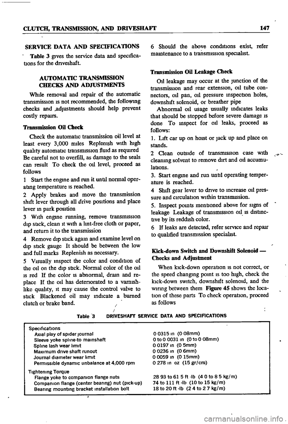
Table
3
gives
the
service
data
and
specIfica
tIons
for
the
dnveshaft
AUTOMATIC
TRANSMISSION
CHECKS
AND
ADJUSTMENTS
Whlle
removal
and
repair
of
the
automatic
transmisSIOn
IS
not
recommended
the
follo
VlIlg
checks
and
adjustments
should
help
prevent
costly
repatrs
Transmission
Oil
Check
Check
the
automatIc
transmission
oil
level
at
least
every
3
000
mlles
Replemsh
With
hIgh
qualIty
automatIc
transmISSIon
flUId
as
reqUIred
Be
careful
not
to
overfill
as
damage
to
the
seals
can
result
To
check
the
011
level
proceed
as
follows
1
Start
the
engme
and
nm
it
untIl
normal
oper
atrng
temperature
IS
reached
2
Apply
brakes
and
move
the
transmission
shut
lever
through
all
drive
pOSItions
and
place
lever
In
park
position
3
WIth
engme
running
remove
tranSmISSIon
dIp
StIck
clean
It
WIth
a
lInt
free
cloth
or
paper
and
return
it
to
the
transmission
4
Remove
dIp
stIck
agam
and
examine
level
on
dIp
stIck
gauge
It
should
be
between
the
low
and
full
marks
Replenish
as
necessary
5
VIsually
InSpect
the
color
and
condItIon
of
the
OIl
on
the
dIp
stIck
Normal
color
of
the
OIl
IS
red
If
the
color
IS
abnormal
dram
and
re
place
If
the
011
has
detenorated
to
a
vamlsh
lIke
qualIty
It
may
cause
the
control
valve
to
stIck
Blackened
oil
may
mdlcate
a
burned
clutch
or
brake
band
6
Should
the
above
condItIons
exist
refer
mamtenance
to
a
transmISSIon
specIalIst
Transmission
Oil
Leakage
Check
011
leakage
may
occur
at
the
Junction
of
the
transmissIon
and
rear
extensIon
011
tube
con
nectors
011
pan
OIl
pressure
mspectIon
holes
downshIft
solenoid
or
breather
pipe
Abnormal
OIl
usage
usually
mdlcates
leaks
that
should
be
stopped
before
severe
damage
IS
done
To
mspect
for
011
leaks
proceed
as
follows
1
LIft
car
up
on
hOISt
or
Jack
up
and
place
on
stands
2
Clean
outsIde
of
transmISSIon
case
With
cleanIng
solvent
to
remove
dIrt
and
011
accumu
latIons
3
Start
engme
and
nm
untIl
operating
temper
ature
is
reached
4
ShIft
gear
lever
to
dnve
to
Increase
011
pres
sure
and
CIrculatIon
WIthin
tranSmISsion
5
Inspect
pOInts
mentIoned
above
for
SIgnS
of
leakage
Leakage
of
transrmSSIOn
011
IS
dIStrnC
tIve
by
its
reddISh
color
6
If
leaks
are
detected
refer
servIce
and
reparr
to
qualIfied
transrmssion
specialISt
Kick
down
Switch
and
Downshift
Solenoid
Checks
and
Adjustment
When
ktck
down
operatIon
IS
not
correct
or
the
speed
changmg
pomt
IS
too
high
check
the
klck
down
SWItch
downshIft
solenOId
and
the
wlDng
between
them
Figure
45
shows
the
loca
tIOn
of
these
parts
To
check
operatIon
proceed
as
follows
Table
3
J
DRIVESHAFT
SERVICE
DATA
AND
SPECIFICATIONS
SpeCifications
Axial
play
of
spider
Journal
Sleeve
yoke
spltne
to
malnshaft
Spline
lash
wear
Itmlt
MaXimum
drive
shaft
runout
Journal
diameter
wear
limit
Penmlsslble
dynamiC
unbalance
at
4
000
rpm
Tightening
Torque
Flange
yoke
to
compaRlon
flange
nuts
CompaRlon
flange
center
bearing
nut
pick
up
Bearing
mounting
bracket
installation
bolt
00315
In
008mm
OtoO
0031
In
OtoO
08mm
00197
In
0
5mm
00236
In
06mm
00059
In
0
15mm
0278
In
oz
15
gr
cm
2893
to
615ft
Ib
40
to
8
5
kg
m
74
to
111
ft
Ib
10
to
15
kg
m
18
to
20
ft
Ib
24
to
2
7
kg
m
Page 154 of 252
CHAPTER
TWELVE
DIFFERENTIAL
REAR
AXLE
AND
REAR
SUSPENSION
The
dIfferential
rear
axle
and
rear
suspen
sIon
dIffer
for
the
various
models
ThIS
chapter
deals
WIth
each
separately
Due
to
the
need
for
SpecIal
tools
and
exper
Ience
to
dIsassemble
and
repaIr
these
unItS
the
followmg
procedures
generally
cover
removal
InspectIon
and
replacement
only
If
mechanIcal
dIfficultIes
eXIst
WIthIn
the
dIfferentIal
and
rear
axle
components
refer
servIce
and
repair
to
a
Datsun
dealer
or
competent
garage
DIFFERENTIAL
SEDAN
The
cast
Iron
dIfferentIal
assembly
used
in
the
sedan
is
shown
in
Figure
1
next
page
Proper
lubncatlOn
of
the
gear
housmg
IS
essen
tIal
Check
lubncant
every
3
000
mlles
and
re
plenISh
as
necessary
Drain
and
refill
lubncant
at
least
every
30
000
miles
Differential
Removal
Sedan
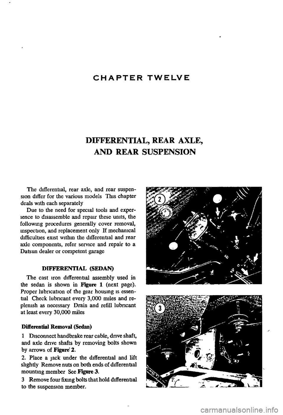
1
DISconnect
handbrake
rear
cable
dnve
shaft
and
axle
dove
shafts
by
removing
bolts
shown
by
arrows
of
Figure
2
2
Place
a
Jack
under
the
dIfferential
and
lift
slIghtly
Remove
nuts
on
both
ends
of
dtfferentIal
mountlng
member
See
Figure
3
3
Remove
four
fixIng
bolts
that
hold
dIfferentIal
to
the
suspensIon
member
Page 156 of 252

DIFFERENTIAL
REAR
AXLE
AND
REAR
SUSPENSION
151
4
Lower
the
Jack
and
r
move
dIfferentIal
from
rear
of
vehIcle
See
Figure
4
After
removal
sup
port
suspensIon
member
wIth
a
stand
to
prevent
distortlon
and
damage
to
the
Insulators
Differential
Inspection
Sedan
The
followmg
mspectIon
can
be
done
WIthout
disassembly
of
the
dIfferential
If
abnormalitIes
or
damage
eXiSts
refer
further
servIce
and
reparr
to
your
dealer
1
Check
the
tooth
contact
pattern
With
lead
oXide
at
two
or
three
pomts
after
removmg
rear
cover
Refer
to
Figure
5
which
shows
the
cor
rect
contact
pattern
If
the
contact
pattern
IS
m
correct
dIsassembly
and
adjustment
of
dIffer
entlalls
reqUIred
CD
TOE
HEEL
DRIVE
SIDE
HEEL
COAST
SIDE
2
Use
a
dIal
mdtcator
to
measure
backlash
be
tween
the
dnve
gear
and
pmIOn
Backlash
should
be
0
0039
to
0
0079
m
0
10
to
o
20mm
Check
all
gear
teeth
for
damage
and
cracks
3
Check
runout
at
the
rear
of
the
dnve
gear
If
the
tooth
contact
pattern
or
backlash
IS
ab
normal
Runout
should
be
less
than
00031
m
0
08mm
See
Figure
6
4
Rotate
the
gears
and
lIsten
for
SignS
of
de
fective
bearmgs
If
noises
are
eVIdent
the
dIf
ferential
must
be
dIsassembled
and
repaired
CD
Diflerentiallnstallation
Sedan
1
Mount
the
dIfferentIal
assembly
to
the
rear
suspensIOn
member
2
FIt
the
dIfferentIal
mountlng
member
to
the
fittmg
hole
by
pushIng
It
forward
with
a
bar
Torque
the
nuts
to
61
ft
lb
8
5
kg
m
3
Install
axle
dnve
shafts
dnve
shaft
and
handbrake
rear
cable
REAR
AXLE
AND
SUSPENSION
SEDAN
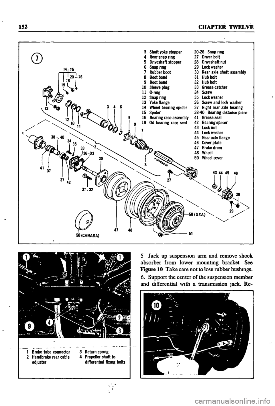
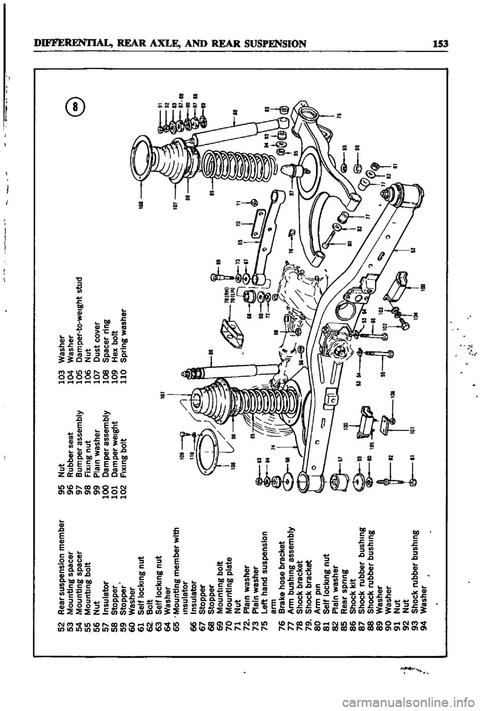
Figure
7
and
Figure
8
page
153
are
ex
ploded
dIagrams
of
the
sedan
rear
axle
and
suspensIOn
The
fully
independent
rear
suspen
SIon
IS
a
semI
traIlIng
arm
deSIgn
With
a
sus
penSIOn
member
suspensIOn
arms
coIl
spnngs
and
hydraulIc
shock
absorbers
The
wheel
bearings
are
lIfetime
lubncated
Rear
Axle
and
Suspension
Removal
Sedan
1
Jack
up
the
rear
of
the
veh1cle
and
support
It
on
stands
2
Remove
wheels
3
Refer
to
Figure
9
and
dtsconnect
handbrake
lInkage
and
rerum
sprmg
Remove
tall
pIpe
and
muffler
4
DISconnect
brake
hose
from
brake
tube
Re
move
four
bolts
holdmg
dnve
shaft
to
dIf
ferential
Lower
dnve
shaft
gently
to
ground
Page 157 of 252
152
CHAPTER
TWELVE
3
Shall
yoke
stopper
0
4
Rear
snap
nng
J
5
Dn
eshall
stopper
6
Snap
nng
7
Rubber
boot
8
Boot
band
9
Boot
band
10
Slee
e
plug
11
O
nng
12
Snap
nng
13
Yoke
flange
3
4
6
14
Whee
beanng
spIder
15
Spider
12
5
16
Beanng
race
assembly
j
50
CANADA
47
AtO
C
J
ty
9
1
Y
4
i
l
A
I
ii
1
o
l
J
Il
h
o
20
J
I
1
Brake
tube
connector
2
Handbrake
rear
cable
adjuster
3
Return
spnng
4
Propeller
shall
to
dlfferenballixlng
bolts
20
26
Snap
nng
27
Dn
er
bolt
28
Onveshall
nut
29
Lock
washer
30
Rear
axle
shall
assembly
31
Hub
bolt
32
Hub
bolt
33
Grease
catcher
34
Screw
35
Lock
washer
36
Screw
and
Ioc
l
washer
37
Right
rear
axle
beanng
38
40
Beanng
distance
piece
41
Grease
seal
42
Beanng
spacer
43
Lock
nut
44
lock
washer
45
Rear
axle
flange
46
Cover
plate
47
Brake
drum
48
Wheel
50
Wheel
oover
43
44
45
46
51
5
Jack
up
suspenSIon
arm
and
remove
shock
absorber
from
lower
mountlng
bracket
See
Figure
10
Take
care
not
to
lose
rubber
bushmgs
6
Support
the
center
of
the
suspensIon
member
and
dIfferential
With
a
transmISsion
Jack
Re
Page 158 of 252
p
52
Rear
suspension
member
95
Nut
103
Washer
53
Mounting
spacer
96
Rubber
seat
104
Washer
e
54
Mounting
spacer
97
Bumper
assembly
105
Damper
to
weight
stud
55
Mounting
bolt
98
Fixmg
nut
106
Nut
56
Nut
99
Plain
washer
107
Dust
cover
57
Insulator
100
Damper
assembly
lOS
Spacer
ring
58
Stopper
101
Damper
weight
109
Hex
bolt
E
59
Stopper
102
FIxing
bolt
110
Spring
washer
60
Washer
61
Self
locking
nut
62
Bolt
63
Self
locking
nut
101
64
Washer
65
Mounting
member
with
Insulator
109
1
l
66
Insulator
110
67
Stopper
w
68
Stopper
E
69
Mountmg
bolt
70
Mounting
plate
@
8IAH
loa
9
181lH
71
Nut
a
72
Plain
washer
73
Plain
washer
75
Left
hand
suspension
a
12
I
ann
t
76
Brake
hose
bracket
77
Arm
bushing
assembly
Ik
I
f
I
f
78
Shock
bracket
M
@
79
Shock
bracket
80
Ann
pin
81
Self
locking
nut
82
Plain
washer
e
85
Rear
spring
v
IDO
86
Shock
kit
M
4r
87
Shock
rubber
bushing
88
Shock
rubber
bushing
105
l1
89
Washer
t
81
r
D9
55
90
Washer
91
Nut
I
Sf
l
I
81
I
92
Nut
93
Shock
rubber
bushing
e
81
101
94
Washer
t
L
Page 159 of 252
154
CHAPTER
tWELVE
move
two
nuts
attachmg
dtfferenual
suspension
member
to
the
body
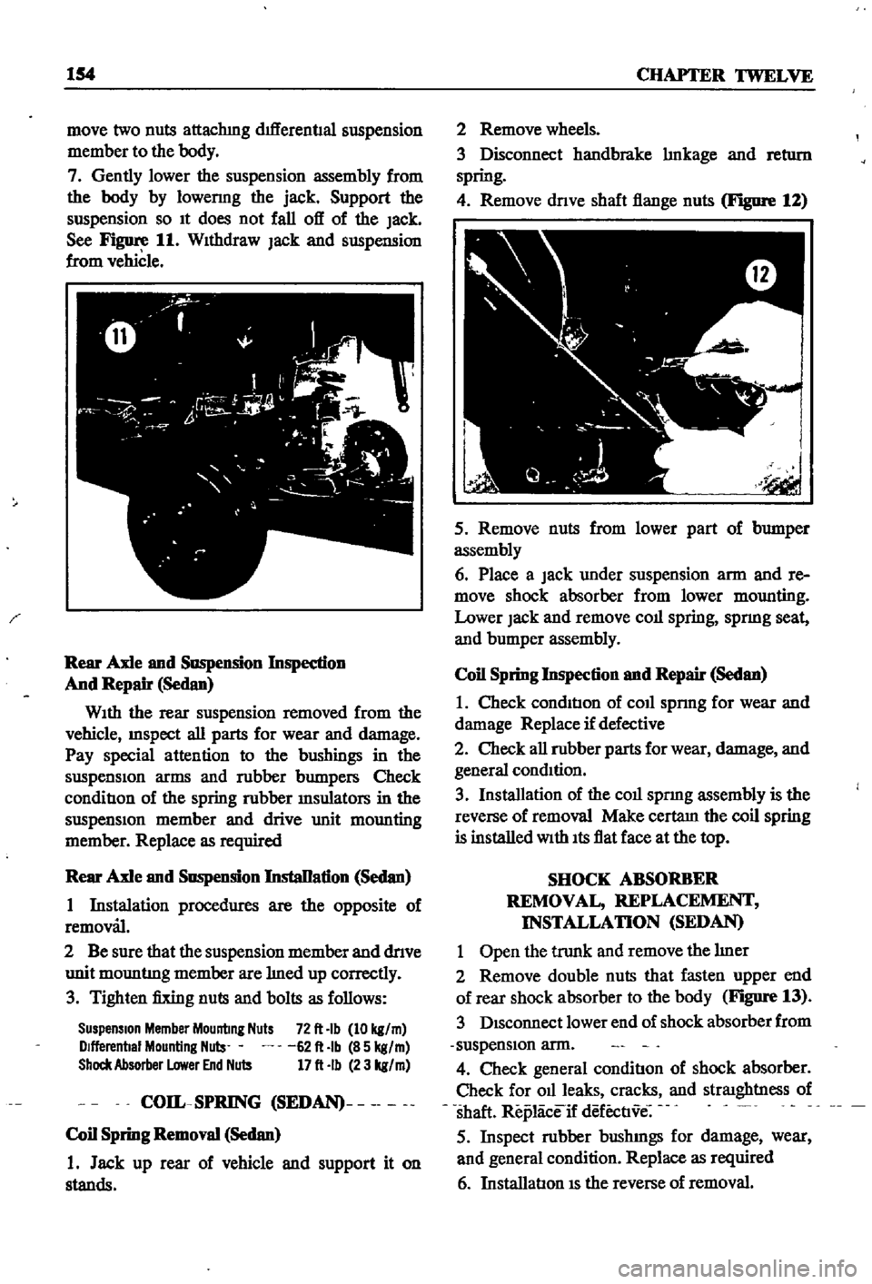
7
Gently
lower
the
suspension
assembly
from
the
body
by
10wermg
the
jack
Support
the
suspension
so
It
does
not
fall
off
of
the
Jack
See
Figure
11
WIthdraw
Jack
and
suspension
from
vehicle
Rear
Axle
and
Suspension
Inspedion
And
Repair
Sedan
WIth
the
rear
suspension
removed
from
the
vehicle
InSpect
all
parts
for
wear
and
damage
Pay
special
attention
to
the
bushings
in
the
suspensIon
arms
and
robber
bumpers
Check
conditIon
of
the
spring
robber
msulators
in
the
suspensIOn
member
and
drive
unit
mounting
member
Replace
as
required
Rear
Axle
and
Suspension
InstaDation
Sedan
1
Instalation
procedures
are
the
opposite
of
removal
2
Be
sure
that
the
suspension
member
and
dnve
unit
mountmg
member
are
med
up
correctly
3
Tighten
fixing
nuts
and
bolts
as
follows
Suspension
Member
Mounting
Nuts
72
It
Ib
10
kg
m
Dlfferenbal
Mounting
Nuls
62
It
Ib
85
kg
m
Shock
Absorber
Lower
End
Nuts
17
It
Ib
23
kg
m
COIL
SPRING
SEDAN
Coil
Spring
Removal
Sedan
1
Jack
up
rear
of
vehicle
and
support
it
on
stands
2
Remove
wheels
3
Disconnect
handbrake
mkage
and
retl1rn
spring
4
Remove
dnve
shaft
flange
nuts
Figure
12
5
Remove
nuts
from
lower
part
of
bumper
assembly
6
Place
a
Jack
under
suspension
arm
and
re
move
shock
absorber
from
lower
mounting
Lower
Jack
and
remove
coll
spring
spnng
seat
and
bumper
assembly
Coil
Spring
Inspection
and
Repair
Sedan
1
Check
condItIon
of
coll
sprmg
for
wear
and
damage
Replace
if
defective
2
Check
all
robber
parts
for
wear
damage
and
general
condItion
3
Installation
of
the
coll
spnng
assembly
is
the
reverse
of
removal
Make
certam
the
coil
spring
is
installed
With
Its
flat
face
at
the
top
SHOCK
ABSORBER
REMOVAL
REPLACEMENT
INSTALLATION
SEDAN
1
Open
the
trunk
and
remove
the
mer
2
Remove
double
nuts
that
fasten
upper
end
of
rear
shock
absorber
to
the
body
Figure
13
3
DIsconnect
lower
end
of
shock
absorber
from
suspensIon
arm
4
Check
general
conditIon
of
shock
absorber
Check
for
011
leaks
cracks
and
straIghtness
of
shaft
Replaceif
defectIve
5
Inspect
robber
bushmgs
for
damage
wear
and
general
condition
Replace
as
required
6
InstallatIon
IS
the
reverse
of
removal
Page 160 of 252
DIFFERENTIAL
REAR
AXLE
AND
REAR
SUSPENSION
155
i
I
I
I
REAR
SUSPENSION
ARM
SEDAN
Rear
Suspension
Arm
Removal
Sedan
1
Jack
up
the
rear
of
the
vehIcle
and
support
It
on
stands
2
Remove
wheel
and
brake
drum
3
DIsconnect
dnve
shaft
from
axle
shaft
4
Remove
handbrake
cable
from
lever
attached
to
wheel
cylInder
5
Plug
brake
tube
to
prevent
loss
of
brake
flwd
6
Remove
wheel
beanng
lock
nut
rear
axle
shaft
wheel
beanngs
and
OIl
seal
Remove
rear
brake
assembly
from
suspensIOn
arm
7
Place
Jack
under
suspenSIon
arm
remove
shock
absorber
from
lower
bracket
lower
Jack
gradually
remove
coll
spnng
spnng
seat
and
bumper
assembly
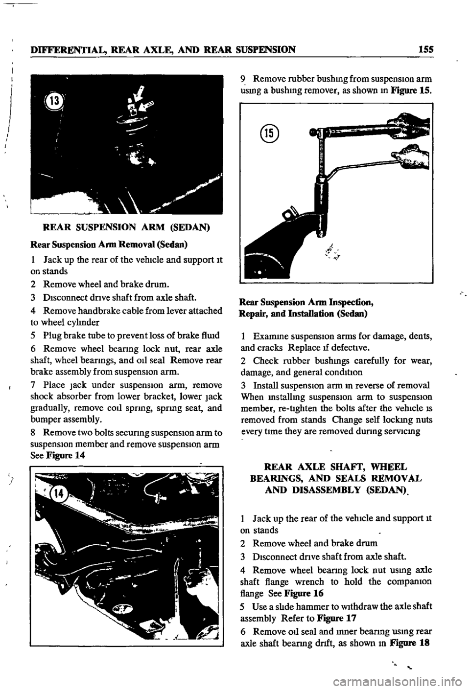
8
Remove
two
bolts
secunng
suspensIOn
arm
to
suspensIOn
member
and
remove
suspensIOn
arm
See
Figure
14
9
Remove
rubber
bushmg
from
suspensIon
arm
usmg
a
bushmg
remover
as
shown
In
Figure
15
@
Rear
SllSpension
Arm
Inspection
Repair
and
Installation
Sedan
1
Examme
suspensIOn
arms
for
damage
dents
and
cracks
Replace
tf
defectIve
2
Check
rubber
bushmgs
carefully
for
wear
damage
and
general
condItIon
3
Install
suspensIOn
arm
m
reverse
of
removal
When
Installmg
suspensIOn
arm
to
suspensIOn
member
re
tIghten
the
bolts
after
the
vehIcle
IS
removed
from
stands
Change
self
lockmg
nuts
every
tIme
they
are
removed
dunng
semcmg
REAR
AXLE
SHAFf
WHEEL
BEARINGS
AND
SEALS
REMOVAL
AND
DISASSEMBLY
SEDAN
1
Jack
up
the
rear
of
the
vehIcle
and
support
It
on
stands
2
Remove
wheel
and
brake
drum
3
DIsconnect
dnve
shaft
from
axle
shaft
4
Remove
wheel
bearmg
lock
nut
usmg
axle
shaft
flange
wrench
to
hold
the
companIOn
flange
See
Figure
16
5
Use
a
slIde
hammer
to
Withdraw
the
axle
shaft
assembly
Refer
to
Figure
17
6
Remove
011
seal
and
Inner
bearmg
usmg
rear
axle
shaft
bearmg
dnft
as
shown
In
Figure
18
Page 163 of 252
158
CHAPTER
TWELVE
REAR
AXLE
AND
SUSPENSION
WAGON
The
rear
axle
is
a
semI
f1oatlng
type
The
rear
wheel
bearmgs
are
presealed
and
do
not
require
penodlc
servIcmg
However
whenever
new
bearmgs
are
Installed
they
should
be
packed
v
lth
wheel
beanng
grease
durmg
InstallatIon
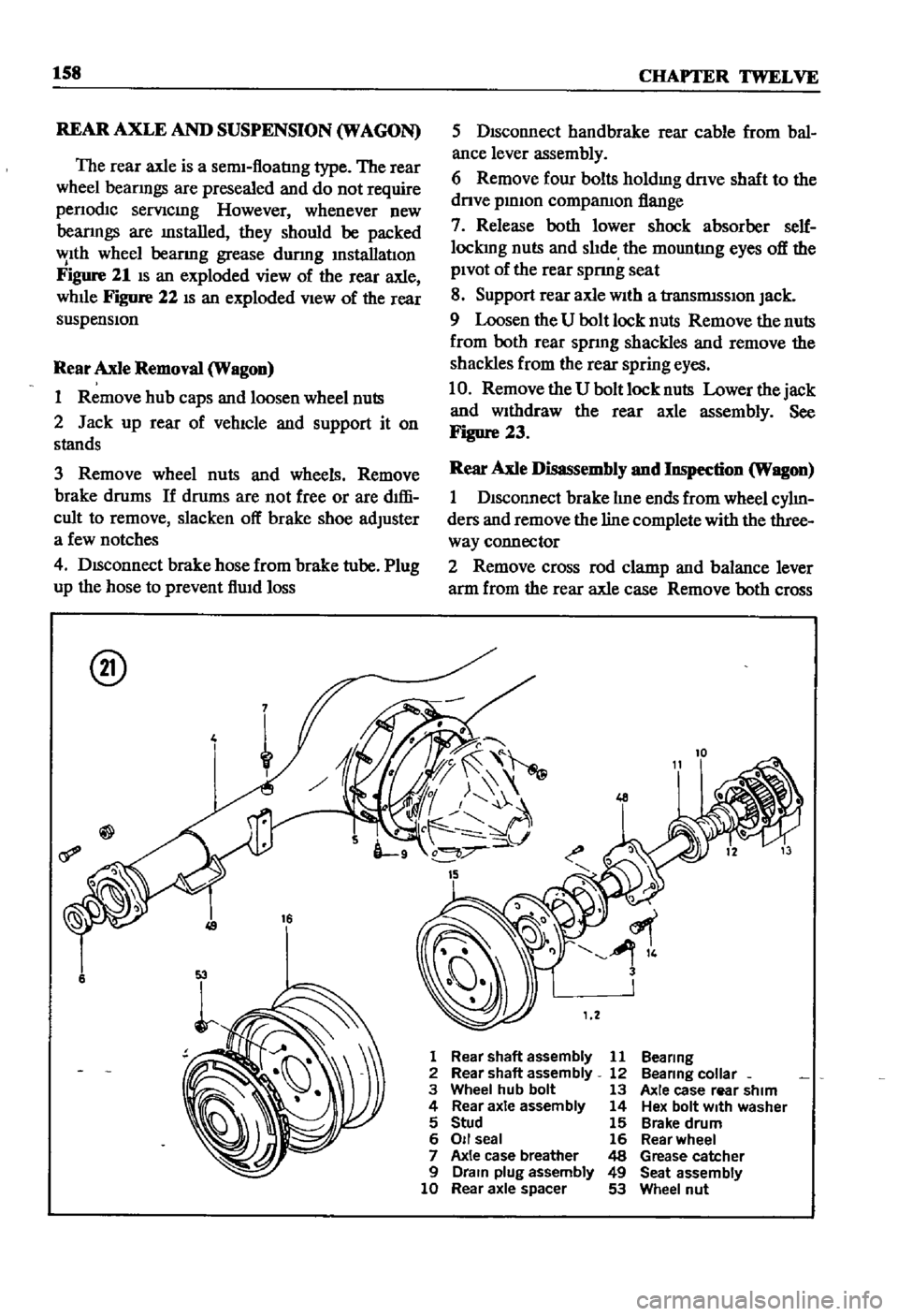
Figure
21
IS
an
exploded
view
of
the
rear
axle
whlle
Figure
22
IS
an
exploded
VIew
of
the
rear
suspensIon
Rear
Axle
Removal
Wagon
1
Remove
hub
caps
and
loosen
wheel
nuts
2
Jack
up
rear
of
vehIcle
and
support
it
on
stands
3
Remove
wheel
nuts
and
wheels
Remove
brake
drums
If
drums
are
not
free
or
are
dIffi
cult
to
remove
slacken
off
brake
shoe
adjuster
a
few
notches
4
DISconnect
brake
hose
from
brake
tube
Plug
up
the
hose
to
prevent
f1Uld
loss
@
4
16
6
5
DIsconnect
handbrake
rear
cable
from
bal
ance
lever
assembly
6
Remove
four
bolts
holdmg
dnve
shaft
to
the
dnve
pmlon
compamon
flange
7
Release
both
lower
shock
absorber
self
lockmg
nuts
and
slIde
the
mountlng
eyes
off
the
PIvot
of
the
rear
spnng
seat
8
Support
rear
axle
wIth
a
transrmsslOn
Jack
9
Loosen
the
U
bolt
lock
nuts
Remove
the
nuts
from
both
rear
spnng
shackles
and
remove
the
shackles
from
the
rear
spring
eyes
10
Remove
the
U
bolt
lock
nuts
Lower
the
jack
and
WIthdraw
the
rear
axle
assembly
See
Figure
23
Rear
Axle
Disassembly
and
Inspection
Wagon
1
DIsconnect
brake
lIne
ends
from
wheel
cylIn
ders
and
remove
the
line
complete
with
the
three
way
connector
2
Remove
cross
rod
clamp
and
balance
lever
arm
from
the
rear
axle
case
Remove
both
cross
1
Rear
shaft
assembly
11
Bea
ring
2
Rear
shaft
assembly
12
Bea
ring
colla
r
3
Wheel
hub
bolt
13
Axle
case
rear
shim
4
Rear
axle
assembly
14
Hex
bolt
With
washer
5
Stud
15
Brake
drum
6
011
seal
16
Rear
wheel
7
Axle
case
breather
48
Grease
catcher
9
Drain
plug
assembly
49
Seat
assembly
10
Rear
axle
spacer
53
Wheel
nut