1968 DATSUN 510 brake
[x] Cancel search: brakePage 164 of 252
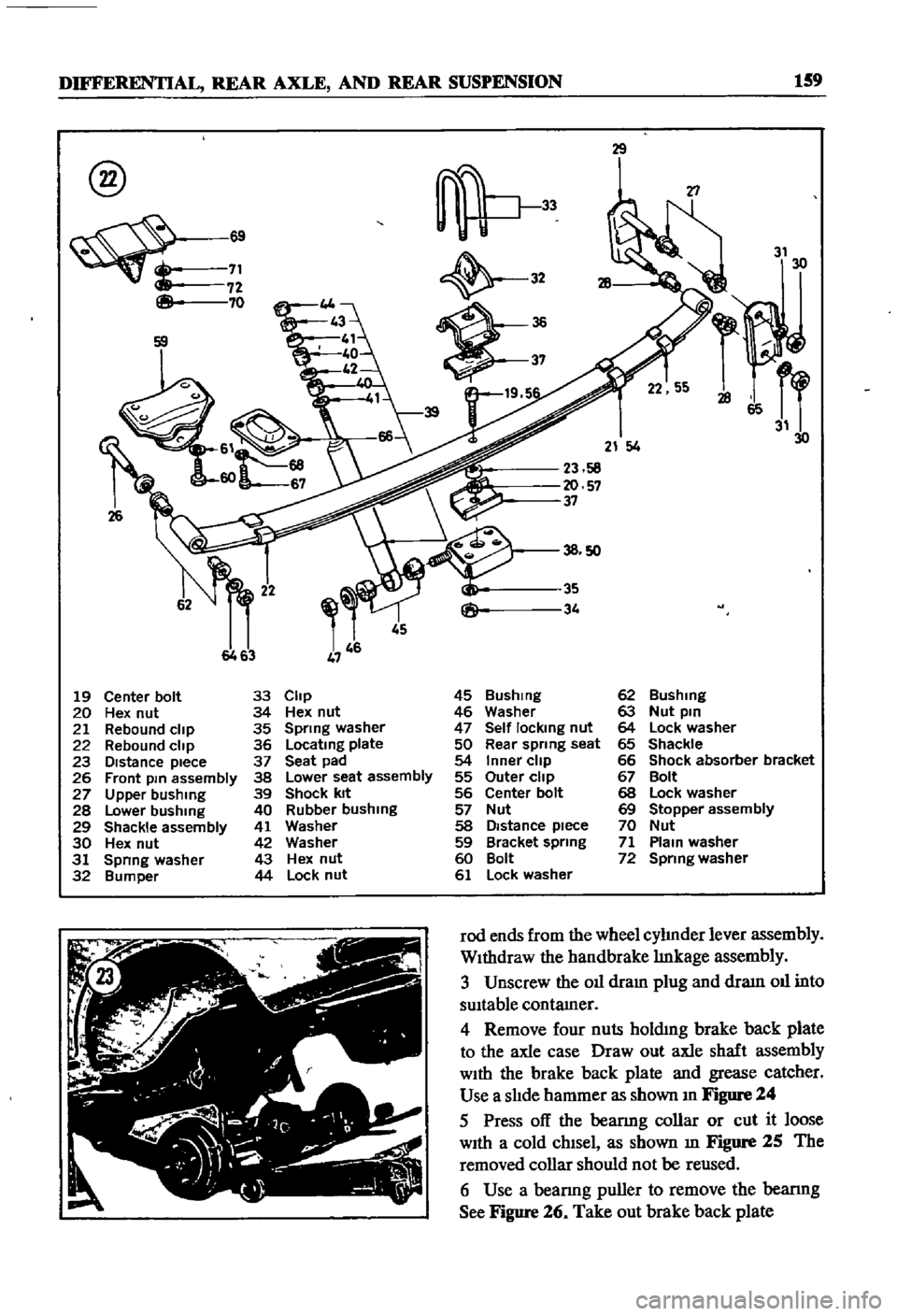
DIFFERENTIAL
REAR
AXLE
AND
REAR
SUSPENSION
159
@
8
69
71
72
70
26
29
32
19
5
T1
31
30
21
4
23
58
20
57
37
45
6463
19
Center
bolt
33
Clip
45
Bushmg
62
Bushing
20
Hex
nut
34
Hex
nut
46
Washer
63
Nut
pin
21
Rebound
clip
35
Spring
washer
47
Self
locking
nut
64
Lock
washer
22
Rebound
clip
36
Locatmg
plate
50
Rear
spring
seat
65
Shackle
23
DIstance
piece
37
Seat
pad
54
Inner
clip
66
Shock
absorber
bracket
26
Front
pm
assembly
38
Lower
seat
assembly
55
Outer
clip
67
Bolt
27
Upper
bushing
39
Shock
kit
56
Center
bolt
68
Lock
washer
28
Lower
bushing
40
Rubber
bushing
57
Nut
69
Stopper
assembly
29
Shackle
assembly
41
Washer
58
Distance
piece
70
Nut
30
Hex
nut
42
Washer
59
Bracket
spring
71
Plam
washer
31
Spnng
washer
43
Hex
nut
60
Bolt
72
Spring
washer
32
Bumper
44
Lock
nut
61
Lock
washer
rod
ends
from
the
wheel
cylInder
lever
assembly
WIthdraw
the
handbrake
lInkage
assembly
3
Unscrew
the
011
dram
plug
and
draIn
011
into
sUItable
contamer
4
Remove
four
nuts
holdmg
brake
back
plate
to
the
axle
case
Draw
out
axle
shaft
assembly
WIth
the
brake
back
plate
and
grease
catcher
Use
a
slIde
hammer
as
shown
In
Figure
24
5
Press
off
the
beanng
collar
or
cut
it
loose
WIth
a
cold
chIsel
as
shown
m
Figure
25
The
removed
collar
should
not
be
reused
6
Use
a
beanng
puller
to
remove
the
bearmg
See
Figure
26
Take
out
brake
back
plate
Page 166 of 252
DIFFERENTIAL
REAR
AXLE
AND
REAR
SUSPENSION
161
T
8
0
to
9
0
kg
m
57
8
to
65
11b
ft
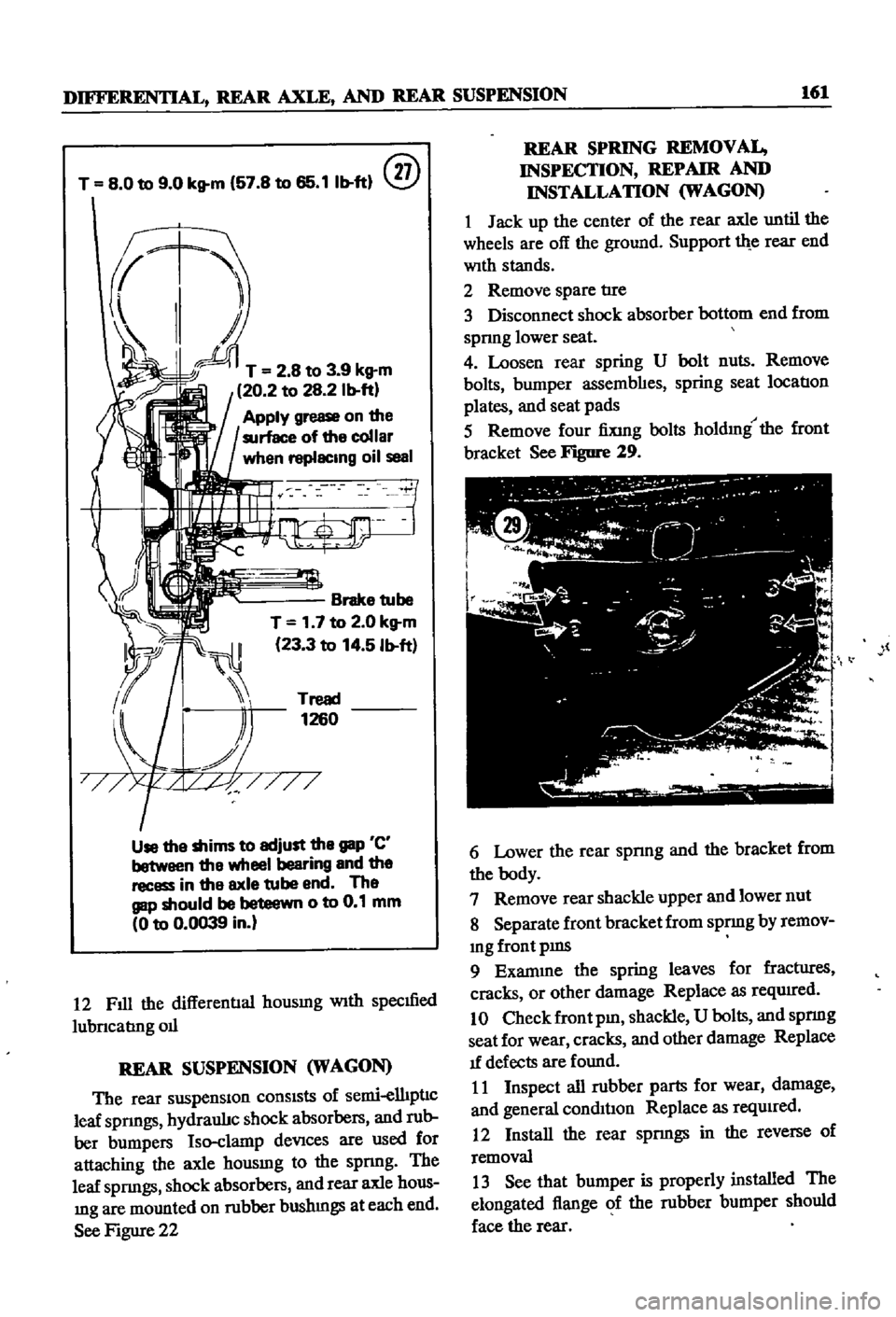
@
T
2
8
to
3
9
kg
m
20
2
to
28
2
Ib
ft
Apply
grease
on
the
surface
of
the
collar
when
replacing
oil
seal
Brake
tube
T
1
7
to
2
0
kg
m
23
3
to
14
5
Ib
ft
Tread
1260
Use
the
shims
to
adjust
the
gap
C
between
the
wheel
bearing
and
the
recess
in
the
axle
tube
end
The
gap
should
be
beteewn
0
to
0
1
mm
0
to
0
0039
in
12
Fill
the
differentIal
housmg
With
specmed
lubncabng
011
REAR
SUSPENSION
WAGON
The
rear
suspensiOn
consists
of
semi
elhpnc
leaf
spnngs
hydraulJc
shock
absorbers
and
rub
ber
bumpers
Iso
clamp
deVices
are
used
for
attaching
the
axle
housmg
to
the
spnng
The
leaf
spnngs
shock
absorbers
and
rear
axle
hous
mg
are
mounted
on
rubber
bushmgs
at
each
end
See
Figure
22
REAR
SPRING
REMOVAL
INSPECTION
REPAIR
AND
INSTALLATION
WAGON
1
Jack
up
the
center
of
the
rear
axle
until
the
wheels
are
off
the
ground
Support
th
e
rear
end
With
stands
2
Remove
spare
tIre
3
Disconnect
shock
absorber
bottom
end
from
spnng
lower
seat
4
Loosen
rear
spring
U
bolt
nuts
Remove
bolts
bumper
assembhes
spring
seat
location
plates
and
seat
pads
5
Remove
four
fiXing
bolts
holdmg
the
front
bracket
See
Figure
29
l
6
Lower
the
rear
spnng
and
the
bracket
from
the
body
7
Remove
rear
shackle
upper
and
lower
nut
8
Separate
front
bracket
from
spnng
by
remov
mg
front
pms
9
Exanune
the
spring
leaves
for
fractIires
cracks
or
other
damage
Replace
as
reqwred
10
Check
front
pm
shackle
U
bolts
and
spnng
seat
for
wear
cracks
and
other
damage
Replace
1f
defects
are
found
11
Inspect
all
rubber
parts
for
wear
damage
and
general
condil1on
Replace
as
reqUired
12
Install
the
rear
spnngs
in
the
reverse
of
removal
13
See
that
bumper
is
properly
installed
The
elongated
flange
of
the
rubber
bumper
should
face
the
rear
Page 167 of 252

162
CHAPTER
TWELVE
14
Coat
the
front
bracket
pm
and
bushmg
and
shackle
pm
and
bushing
With
a
soap
solution
pnor
to
assembly
15
The
front
pm
secunng
nut
and
shock
ab
sorber
lower
end
securmg
nut
should
be
re
tightened
after
the
vehicle
is
sittmg
on
the
ground
16
Make
certaJn
the
shackle
bushmg
flange
is
clamped
evenly
on
both
Sides
SHOCK
ABSORBER
REMOVAL
INSPECTION
AND
INSTALLATION
WAGON
1
Jack
up
the
center
of
the
rear
axle
and
sup
port
th
e
axle
housmg
With
stands
2
Reinove
the
lower
end
of
the
rear
shock
absorber
from
spring
seat
3
Loosen
the
four
bolts
secunng
the
upper
bracket
to
body
Remove
shock
absorber
and
upper
bracket
4
Check
shock
absorber
for
leaks
and
cracks
Check
the
shaft
for
straighmess
Replace
1f
defective
5
Inspect
rubber
bushmgs
for
damage
cracks
and
general
condition
Replace
1f
defective
6
Install
the
shock
absorber
by
reversing
the
procedure
used
durmg
removal
DIFFERENTIAL
pICK
UP
The
dlfferenl1al
carner
IS
made
up
of
alum
mum
alloy
and
uses
a
hyp01d
bevel
gear
Proper
lubncatIon
IS
essenl1al
Check
and
replemsh
the
lubncant
every
3
000
mlles
Drain
and
refill
every
30
000
inlles
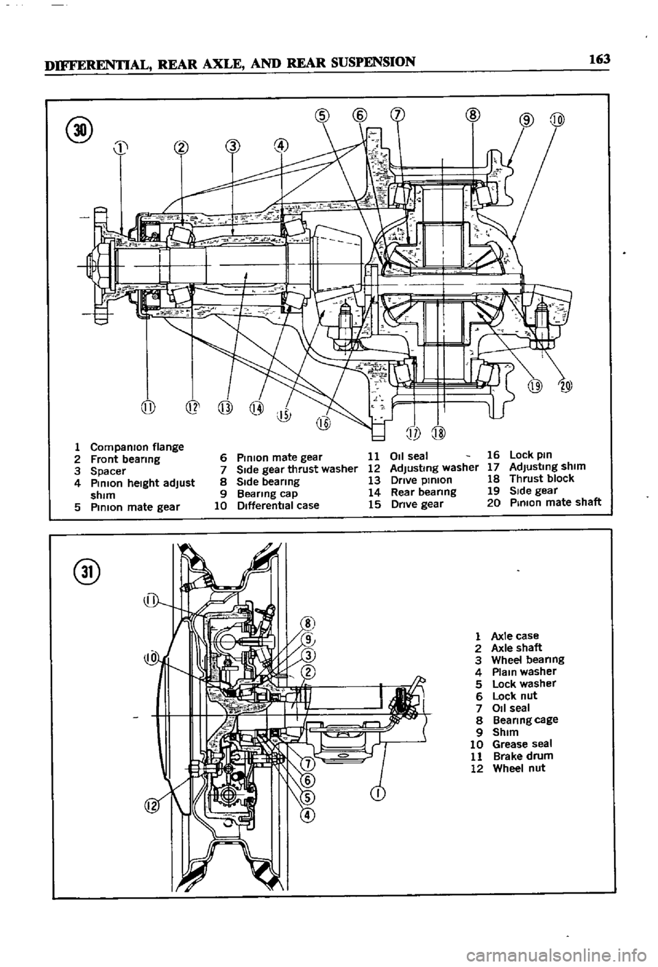
Figure
30
IS
a
cross
sectional
View
of
the
pick
up
dIfferential
Difterential
Removal
Pick
up
1
Jack
up
the
rear
wheels
and
support
vehicle
With
stands
2
DIsconnect
dnve
pmlOn
companlOn
flange
to
yoke
connectIon
3
Remove
rear
axles
as
descnbed
later
m
thIS
chapter
4
Remove
dlfferenl1al
gear
assembly
Difterential
Inspection
Pick
up
The
followmg
mspection
can
be
done
Without
disassembly
of
the
d1fferenl1al
If
abnormahties
or
damage
eXiSts
refer
further
serVice
and
reparr
to
your
dealer
1
Check
the
tooth
contact
pattern
WIth
lead
OXide
at
two
or
three
pomts
after
remoVlDg
rear
cover
Refer
to
FIgure
5
for
correct
contact
pattern
If
the
pattern
IS
faulty
disassembly
and
adJustment
of
the
dIfIerentialIs
required
2
Measure
backlash
between
dnve
gear
and
pmlOn
With
a
dial
mdlcator
Backlash
should
be
00051
to
0
0071
m
013
to
0
18mm
3
Rotate
the
gears
and
lISten
for
SignS
of
bear
mg
noise
4
Inspect
gear
teeth
for
SIgnS
of
damage
or
cracks
Difterential
Installation
Pick
up
Install
the
differential
by
reversmg
the
pro
cedures
used
dunng
removal
REAR
AXLE
AND
SUSPENSION
pICK
UP
The
rear
axle
IS
of
the
semi
floatIng
type
The
rear
wheels
use
tapered
roller
beanngs
Figure
31
IS
a
cross
sectional
view
of
the
rear
axle
REAR
SUSPENSION
TORQUE
TIGHTENING
SPECIFICATIONS
WAGON
Shock
absorber
upper
bracket
to
body
bolts
Shock
absorber
to
upper
bracket
lock
nuts
Shock
absorber
to
lower
bracket
lock
nuts
Rear
spnng
U
bolt
nuts
Shackle
nuts
Front
pm
nuts
Front
bracket
flxmg
nuts
Brake
dISC
to
rear
housmg
bolts
DifferentIal
carner
to
axle
housmg
bolt
Dnve
shaft
flange
nuts
11
to
18
ft
Ib
1
5
to
2
5
kg
m
12
to
16
ft
db
17
to
2
2
kg
m
25
to
33
ft
Ib
35
to
45
kg
m
43
to
47
ft
Ib
60
to
6
5
kg
m
32
to
36
ft
Ib
45
to
50
kg
m
32
to
36
ft
Ib
45
to
5
0
kg
m
13
to
17
ft
Ib
18
to
23
kg
m
20
to
28
ft
Ib
28
to
3
9
kg
m
14
to
16
ft
Ib
20
to
2
2
kg
m
20
to
28
ft
Ib
28
to
3
9
kg
m
Page 168 of 252
DIFFERENTIAL
REAR
AXLE
AND
REAR
SUSPENSION
163
@
j
@
@
@
1
Companron
flange
2
Front
bearmg
3
Spacer
4
Pmlon
heIght
adjust
shim
5
PmlOn
mate
gear
@
6
Pmlon
mate
gear
11
7
Side
gear
thrust
washer
12
8
Side
bearmg
13
9
Bearing
cap
14
10
Differential
case
15
011
seal
Adjusting
washer
Drive
pmlon
Rear
beanng
Drive
gear
16
Lock
pm
17
AdJustmg
shim
18
Thrust
block
19
SIde
gear
20
Pmlon
mate
shaft
@
1
Axle
case
2
Axle
shaft
3
Wheel
beanng
4
Plam
washer
5
Lock
washer
6
Lock
nut
7
011
seal
8
Beanngcage
9
Shim
10
Grease
seal
11
Brake
drum
12
Wheel
nut
Page 169 of 252
164
CHAPTER
TWELVE
Rear
Axle
Removal
Pick
up
1
Jack
up
the
vehicle
and
support
It
With
stands
2
Remove
wheels
and
brake
drum
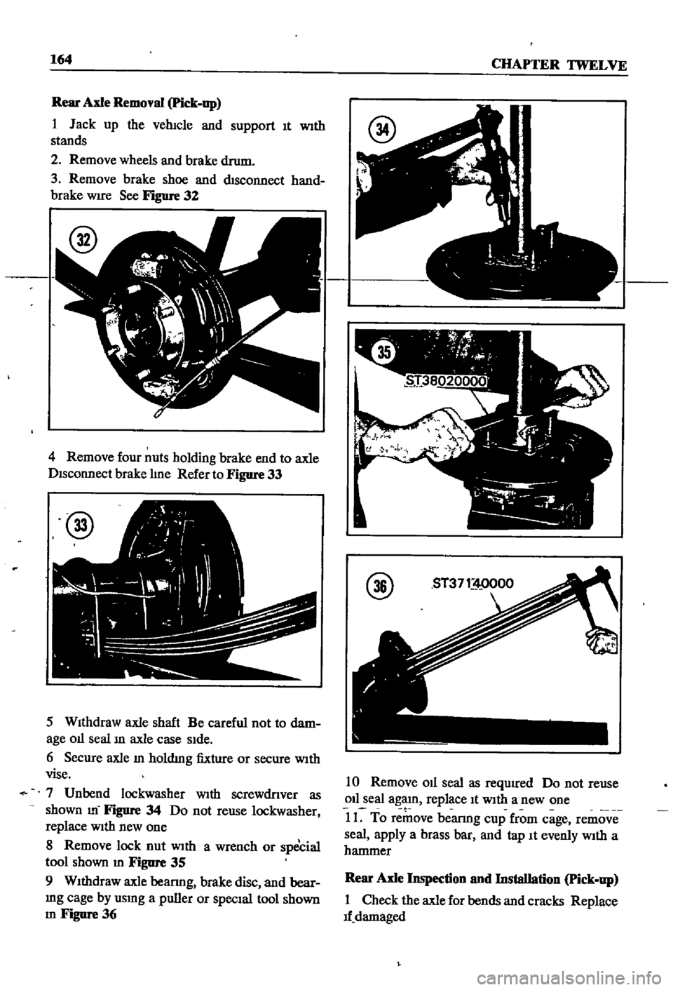
3
Remove
brake
shoe
and
chsconnect
hand
brake
WIre
See
Figure
32
4
Remove
four
nuts
holding
brake
end
to
axle
Disconnect
brake
hne
Refer
to
Figure
33
@
5
WIthdraw
axle
shaft
Be
careful
not
to
dam
age
01l
seal
ill
axle
case
SIde
6
Secure
axle
m
holdmg
fixture
or
secure
WIth
vise
7
Unbend
lockwasher
With
screwdnver
as
shown
m
FIgure
34
Do
not
reuse
lockwasher
replace
With
new
one
8
Remove
lock
nut
With
a
wrench
or
special
tool
shown
m
Figure
35
9
WIthdraw
axle
beanng
brake
disc
and
bear
mg
cage
by
usmg
a
puller
or
SpecIal
tool
shown
m
Figure
36
@
10
Remove
011
seal
as
required
Do
not
reuse
011
seal
agaJn
replace
It
With
a
new
one
t
11
To
remove
bearmg
cup
from
cage
remove
seal
apply
a
brass
bar
and
tap
It
evenly
With
a
hammer
Rear
Axle
Inspection
nnd
Installation
Pick
up
1
Check
the
axle
for
bends
and
cracks
Replace
1f
damaged
Page 170 of 252
DIFFERENTIAL
REAR
AXLE
AND
REAR
SUSPENSION
165
2
Check
wheel
bearmgs
for
damage
or
noise
Replace
them
If
defective
3
Be
sure
to
use
new
011
seals
and
lockwashers
4
FIt
beanng
cup
and
grease
seal
to
cage
Tap
WIth
a
brass
hammer
while
fittIng
FIll
grease
seal
IIp
With
wheel
beanng
grease
after
fittmg
5
Install
brake
diSC
and
beanng
cage
on
axle
Fit
bearmg
cone
With
brass
bar
6
Tighten
lock
nut
Place
faced
Side
of
nut
to
washer
SIde
so
that
washer
IS
not
damaged
Torque
lock
nut
to
10S
to
145
ft
lb
15
to
20
kg
m
7
Match
washer
IIp
With
groove
m
nut
tIghten
nut
and
bend
washer
carefully
to
prevent
hp
damage
S
Use
a
brass
bar
to
fit
011
seal
to
tube
end
When
fitted
apply
grease
to
the
hp
Be
careful
not
to
deform
seal
or
damage
hp
9
Completely
fill
bearmg
With
grease
10
Install
shaft
AdJust
aXial
clearance
With
shIms
See
Figure
37
Clearance
should
be
0
012
to
0
035
m
0
3
to
09mm
Standard
shIm
thickness
IS
0
059
m
1
5mm
@
11
Install
other
shaft
AdJust
aXlal
clearance
With
shIm
Clearance
should
be
0
OOOS
to
0
0059
m
002
to
0
15mm
12
Install
bolts
and
torque
to
26
to
34
ft
lb
3
6
to
4
7
kg
m
REAR
SUSPENSION
PICK
UP
The
rear
suspension
IS
a
banJO
type
ngId
suspensIOn
With
parallel
semI
elhpnc
leaf
spnngs
Front
and
rear
ends
of
the
springs
are
secured
on
the
frame
with
rubber
bushmgs
Shock
absorbers
are
mstalled
on
the
cross
mem
ber
from
the
spnng
lower
pad
Figure
38
next
page
IS
an
exploded
dIagram
of
the
rear
sus
pensIOn
Rear
Suspension
Assembly
Removal
Pick
up
1
Jack
up
rear
of
vehicle
and
support
It
With
stands
Remove
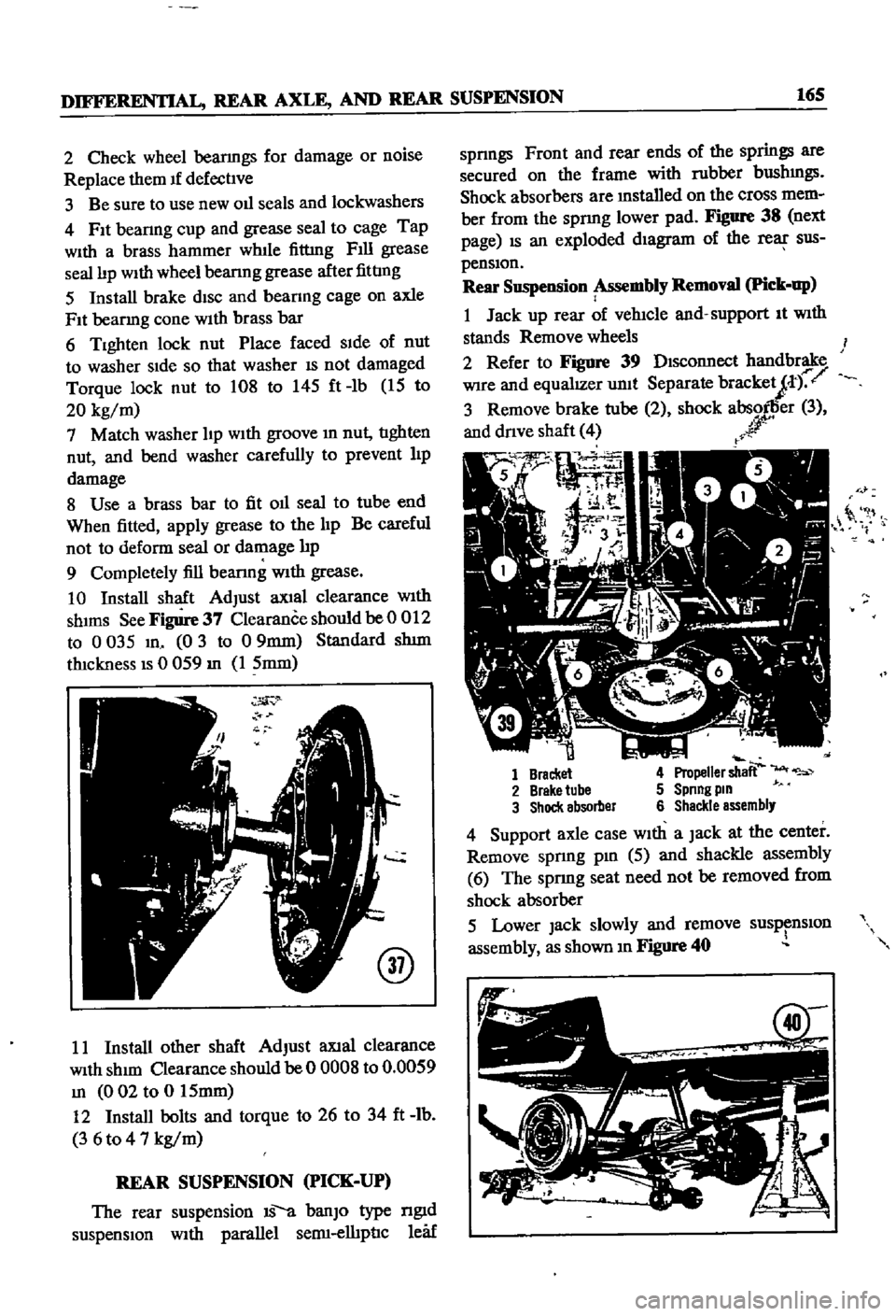
wheels
2
Refer
to
Figure
39
DIsconnect
handbrake
Wire
and
equalIZer
unit
Separate
bracketJt
r
3
Remove
brake
tube
2
shock
absorller
3
and
dnve
shaft
4
r
r
0
it
1
Bracket
4
Propeller
shaft
2
Brake
tube
5
Spnng
pm
3
Shock
absorber
6
Shackle
assembly
4
Support
axle
case
With
a
Jack
at
the
center
Remove
spnng
pm
5
aJId
shackle
assembly
6
The
sprmg
seat
need
not
be
removed
from
shock
absorber
5
Lower
Jack
slowly
and
remove
susp
nslOn
assembly
as
shown
m
Figure
40
Page 171 of 252
166
CHAPTER
TWELVE
u
@
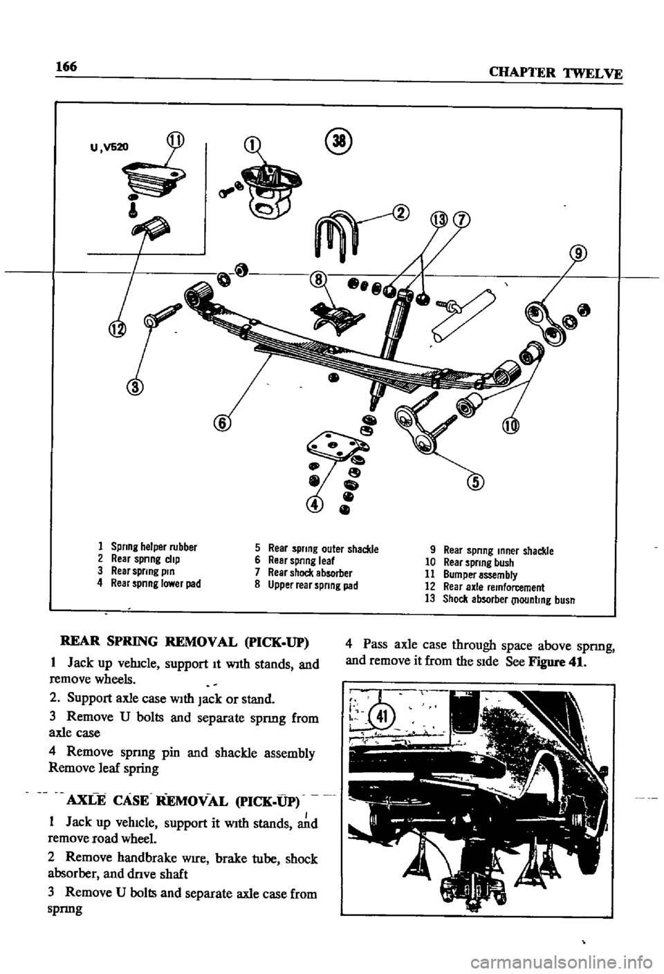
1
Spring
helper
rubber
5
Rear
spring
outer
shackle
9
Rear
spring
mner
shackle
2
Rear
spnng
clip
6
Rear
spring
leaf
10
Rear
spring
bush
3
Rear
sprmg
pm
7
Rear
shock
absorber
11
Bumper
assembly
4
Rear
spnnglawerpad
8
Upper
rear
spring
pad
12
Rear
axle
remforcement
13
Shock
absorber
llountmg
busn
REAR
SPRING
REMOVAL
pICK
UP
1
Jack
up
vehicle
support
It
With
stands
and
remove
wheels
2
Support
axle
case
With
Jack
or
stand
3
Remove
U
bolts
and
separate
spnng
from
axle
case
4
Remove
spnng
pin
and
shackle
assembly
Remove
leaf
spring
AXLE
CASE
REMOVAL
PICK
UP
1
Jack
up
vehIcle
support
it
With
stands
Jd
remove
road
wheel
2
Remove
handbrake
Wire
brake
tube
shock
absorber
and
dnve
shaft
3
Remove
U
bolts
and
separate
axle
case
from
spnng
4
Pass
axle
case
through
space
above
spnng
and
remove
it
from
the
SIde
See
Figure
41
Page 173 of 252
CHAPTER
THIRTEEN
FRONT
AXLE
FRONT
SUSPENSION
AND
STEERING
A
strut
type
front
suspension
IS
used
on
sedans
and
wagons
The
shock
absorber
and
the
spmdle
are
a
smgle
urnt
which
is
supported
by
a
coIl
spnng
on
the
upper
end
and
by
the
trans
verse
lInk
on
the
lower
end
Figures
1
2
nnd
3
are
exploded
dIagrams
of
the
axle
and
suspen
SIon
system
used
FIgure
1
Illustrates
the
axle
Figure
2
shows
the
sedan
suspenSlOn
and
FIgure
3
covers
the
wagon
Front
suspensIOn
on
the
pIck
up
IS
a
double
wIShbone
mdependent
deSign
which
uses
torsIon
bars
Figure
4
IS
a
cross
sectional
view
WHEEL
HUB
AND
WHEEL
BEARING
SEDAN
AND
WAGON
Wheel
Hub
nnd
Wheel
Bearing
Removal
Sednn
aud
Wagon
1
Jack
up
the
front
of
the
vehicle
and
support
It
on
stands
2
Remove
the
wheels
3
Detach
brake
hose
connector
at
frame
4
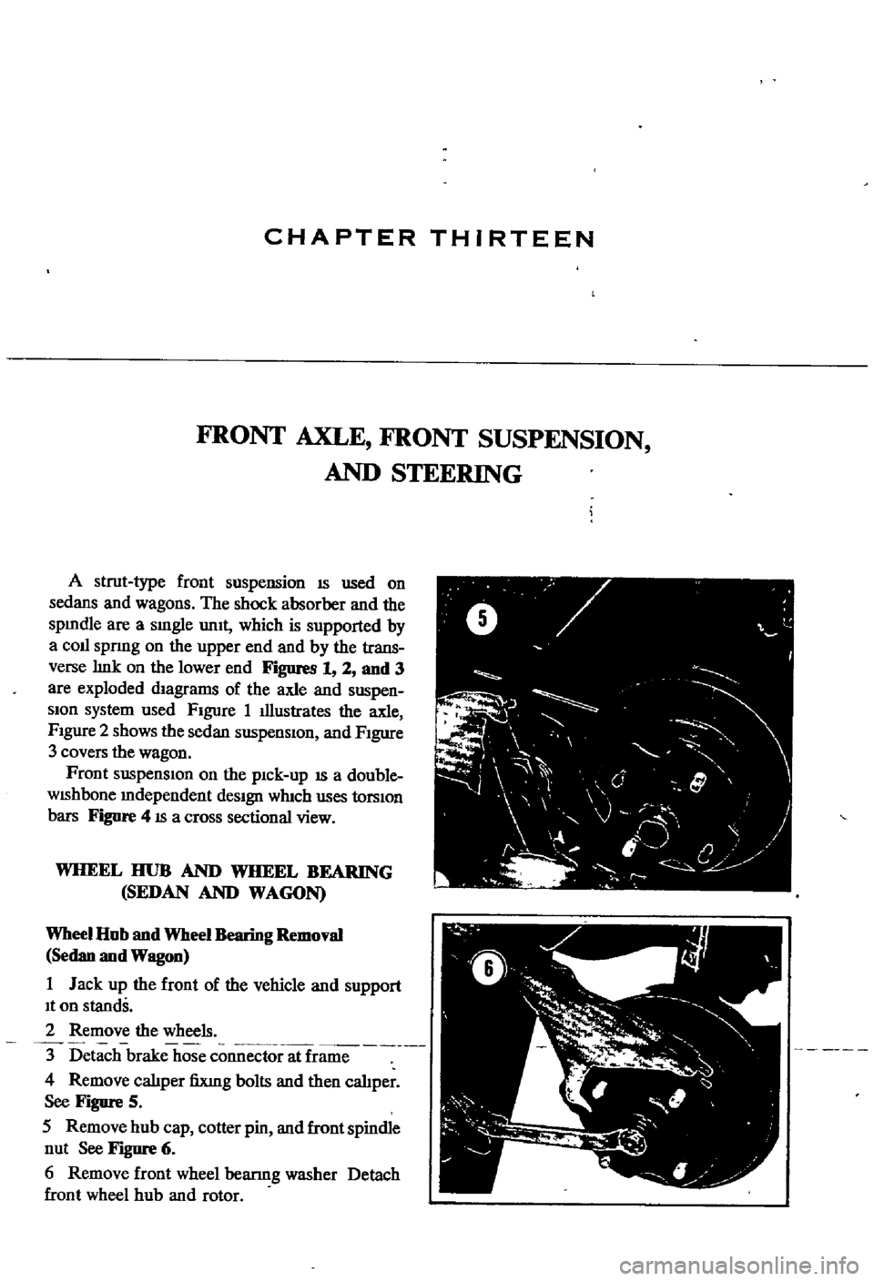
Remove
calIper
fiXlng
bolts
and
then
cahper
See
Figure
5
5
Remove
hub
cap
cotter
pin
and
front
spindle
nut
See
Figure
6
6
Remove
front
wheel
bearmg
washer
Detach
front
wheel
hub
and
rotor
ft
V
0
y
F
I
I
J
j
0
l
l
4
f