1968 DATSUN 510 brake
[x] Cancel search: brakePage 179 of 252
174
CHAPTER
THIRTEEN
Spring
and
StnJt
Assembly
Removal
nnd
Installation
1
Jack
up
the
front
of
the
car
and
support
it
on
stands
2
Remove
front
wheel
3
Detach
brake
hose
connector
at
frame
Re
move
lock
spnng
and
disconnect
brake
hose
from
brake
tube
Plug
up
end
of
tube
so
that
brake
f1wd
will
not
leak
out
4
D
etacb
tensiQn
rod
fi
g
bolts
lld
stabilizer
fixmg
nut
Remove
from
transverse
hnk
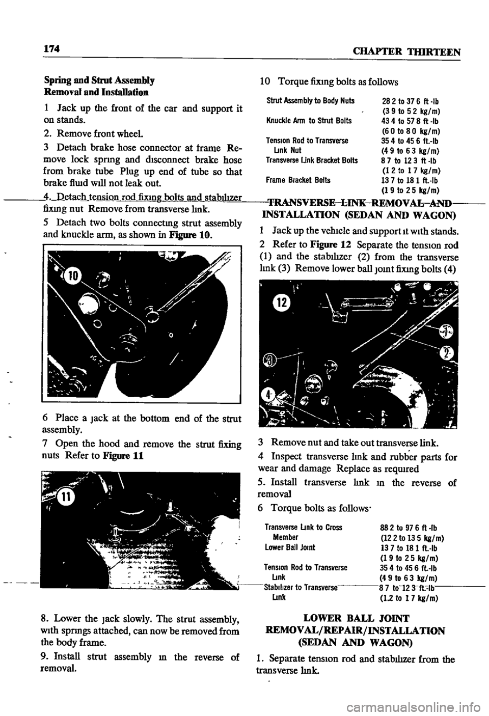
5
Detach
two
bolts
connectmg
strut
assembly
and
knuckle
arm
as
shown
in
Figure
10
6
Place
a
Jack
at
the
bottom
end
of
the
strut
assembly
7
Open
the
hood
and
remove
the
strut
fixing
nuts
Refer
to
Figure
11
8
Lower
the
Jack
slowly
The
strut
assembly
With
spnngs
attached
can
now
be
removed
from
the
body
frame
9
Install
strut
assembly
m
the
reverse
of
removal
10
Torque
fiXlng
bolts
as
follows
Strut
Assembly
to
Body
Nuts
282
to
37
6
fl
Ib
3
9
to
5
2
kg
m
434
to
578
fl
Ib
60
to
80
kg
m
35
4
to
45
6
flAb
49
to
6
3
kg
m
8
7
to
123
fl
Ib
12
to
17
kg
m
13
7
to
18
1
flAb
19
to
25
kg
m
TRANSVERSE
l
INK
REMOV
AL
AND
INSTALLATION
SEDAN
AND
WAGON
1
Jack
up
the
vehicle
and
supportIt
With
stands
2
Refer
to
Figure
12
Separate
the
tensIOn
rod
1
and
the
stabIlIzer
2
from
the
transverse
hnk
3
Remove
lower
ball
Jomt
fixmg
bolts
4
Knuckle
Ann
to
Strut
Bolts
TenSion
Rod
to
Transverse
L
mk
Nut
Transverse
Unk
Bracket
Bolts
Frame
Bracket
Bolts
3
Remove
nut
and
take
out
transverse
link
4
Inspect
transverse
hnk
and
rubber
parts
for
wear
and
damage
Replace
as
reqwred
5
Install
transverse
hnk
III
the
reverse
of
removal
6
Torque
bolts
as
follows
Transverse
L
mk
to
Cross
Member
L
ower
Ball
Jomt
882
to
976
fl
lb
122
to
13
5
kg
m
13
7
to
18
1
flAb
19
to
25
kg
m
TenSion
Rod
to
Transverse
354
to
45
6
fl
lb
L
lnk
49
to
63
kg
m
Stabilizer
to
Transverse
8
7
to
123
fl
lb
L
lnk
1
2
to
17
kg
m
LOWER
BALL
JOINT
REMOVAL
REPAIR
INSTALLATION
SEDAN
AND
WAGON
1
Separate
tensIOn
rod
and
stabilizer
from
the
transverse
hnk
Page 180 of 252
FRONT
AXLE
FRONT
SUSPENSION
AND
STEERING
175
2
Remove
bolt
cormectIng
strut
and
knuckle
arm
3
Remove
cotter
pm
and
lower
ball
Joint
4
Separate
lower
ball
Jomt
from
knuckle
arm
5
Remove
bolts
for
lower
ball
Jomt
Separate
transverse
lmk
from
lower
ball
Joint
6
Inspect
ball
Jomt
and
dust
cover
for
wear
or
damage
Replace
as
requIred
If
end
play
m
the
aXial
dIrectIon
of
the
ball
Jomt
exceeds
00012
to
0
0136
m
0
03
to
0
6mm
replace
It
7
Install
ball
Jomt
m
the
reverse
of
removal
Grease
It
through
the
grease
mpple
Take
care
to
fill
the
caVity
slowly
so
that
grease
does
not
come
out
from
the
clamp
portIon
8
Torque
bolts
as
follows
Lower
Ball
JOint
to
Transverse
Link
Ball
Stud
Nut
13
7
to
18
1
fl
Ib
19
to
25
kgfm
398
to
55
0
fl
Ib
55
to
76
kgfm
43
4
to
57
8
flAb
60
to
80
kgfm
35
4
to
45
6
flAb
49
to
63
kgfm
87
to
12
3
fl
lb
12
to
17
kgfm
Knuckle
Ann
to
Strut
TenSion
Rod
to
Transverse
Link
Stabilizer
to
Transverse
Link
FRONT
SUSPENSION
ADJUSTMENT
AND
WHEEL
ALIGNMENT
SEDAN
AND
WAGON
Due
to
the
speclahzed
eqUIpment
required
front
suspensIOn
adJustment
and
wheel
ahgn
ment
should
be
referred
to
a
Datsun
dealer
or
front
end
speciahst
The
followmg
specmcations
apply
to
the
sedan
and
wagon
Sedan
Wagon
Caster
1
40
20
00
Camber
1
00
20
10
King
Pin
Incllnallon
8000
7050
Toe
In
0236
to
0
354
In
0118
to
0
236
In
6
to
9mm
3
to
6mm
Steenng
Angle
In
38
to
390
38
to
390
Steenng
Angle
Out
22030
to
330
30
220
30
to
330
30
Front
Axle
Removal
Pick
up
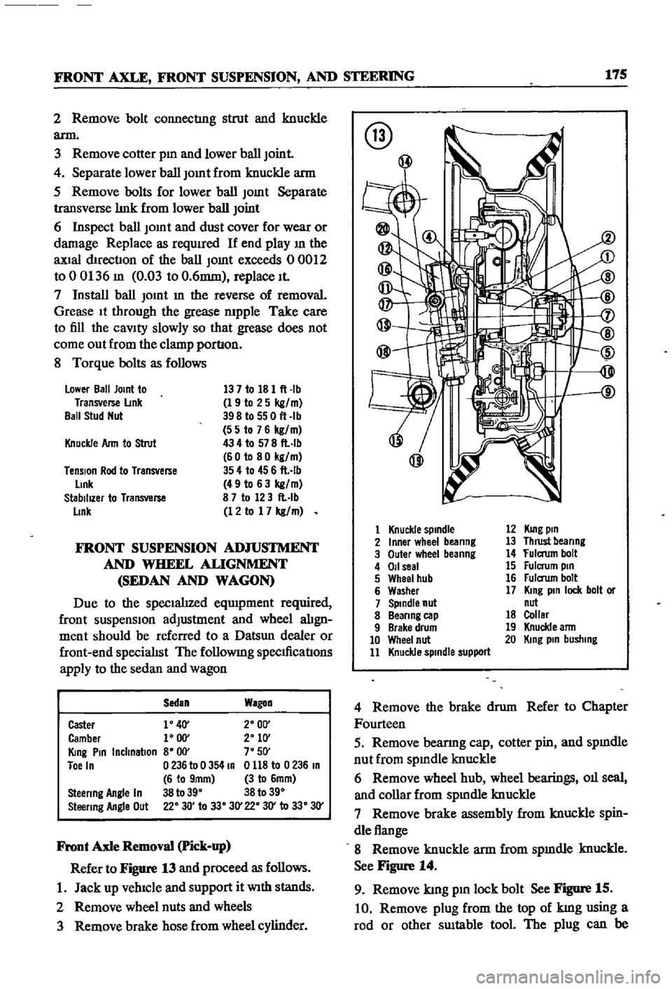
Refer
to
Figure
13
and
proceed
as
follows
1
Jack
up
vehIcle
and
support
it
With
stands
2
Remove
wheel
nuts
and
wheels
3
Remove
brake
hose
from
wheel
cylinder
@
@
1
Knuckle
spindle
2
Inner
wheel
beanng
3
Outer
wheel
beanng
4
011
seal
5
Wheel
hub
6
Washer
7
Spindle
nut
8
Beanng
cap
9
Brake
drum
10
Wheel
nut
11
Knuckle
spindle
support
12
KUlg
pin
13
Thrust
beanng
14
fulaum
bolt
15
Fulcrum
pin
16
Fulaum
bolt
17
King
pin
lock
bolt
or
nut
18
Collar
19
Knuckle
ann
20
King
pin
busllIng
4
Remove
the
brake
drum
Refer
to
Chapter
Fourteen
5
Remove
bearmg
cap
cotter
pin
and
spmdle
nut
from
spmdle
knuckle
6
Remove
wheel
hub
wheel
bearings
011
seal
and
collar
from
spmdle
knuckle
7
Remove
brake
assembly
from
knuckle
spin
dle
flange
8
Remove
knuckle
arm
from
spmdle
knuckle
See
Figure
14
9
Remove
kmg
pm
lock
bolt
See
Figure
15
10
Remove
plug
from
the
top
of
kmg
using
a
rod
or
other
SUItable
tool
The
plug
can
be
Page 182 of 252
FRONT
AXLE
FRONT
SUSPENSION
AND
STEERING
177
5
Check
front
hub
for
cracks
and
damage
Re
place
1f
defectIve
6
Check
thrust
bearmg
for
wear
damage
rust
and
ease
of
rotatIon
Replace
1f
defectIve
Front
Suspension
Installation
1
Remstallation
is
the
reverse
of
removal
2
Apply
hght
coatIng
of
multI
purpose
grease
to
all
shdmg
parts
3
Install
bushmg
carefully
so
that
grease
groove
IS
on
the
upper
Side
and
the
bushmg
Joint
is
faced
rearward
Remove
grease
mpple
and
dn11
grease
hole
through
bushmg
through
hole
With
an
0
1181
m
3mm
dn11
Remove
metal
shaVlDgs
and
burrs
Ream
the
mner
d1ameter
of
the
bushing
to
07878
to
0
7888
m
20
010
to
20035mm
4
Install
thrust
bearmg
so
that
the
covered
face
Side
is
upward
5
Push
up
the
bottom
of
the
spmdle
hghtly
Measure
clearance
and
select
a
spmdle
shim
to
prOVide
the
followmg
clearance
standard
Clearance
0
001
In
004mm
ShIms
are
available
m
vanous
thicknesses
6
FIt
kmg
pm
and
make
certam
It
operates
smoothly
7
Apply
sealer
to
new
plug
and
install
8
Install
bearmg
outer
race
Fill
wheel
hub
and
hub
cap
With
multI
purpose
grease
Fill
space
between
wheel
bearing
rollers
and
grease
seal
hp
pocket
With
multI
purpose
grease
Make
cer
tam
wheel
beanngs
are
coated
completely
9
Apply
multI
purpose
grease
to
spmdle
shaft
wheel
bearmg
washer
and
to
the
wheel
bearmg
lock
nut
10
Make
certam
that
no
dIrt
or
foreign
matenal
IS
permitted
m
contact
with
parts
or
grease
dunng
assembly
Wheel
Bearing
Adjustment
1
Install
spindle
nut
and
torque
to
23
1
to
24
6
ft
lb
3
2
to
3
4
kg
m
2
Turn
wheel
hub
a
few
tImes
m
both
the
clock
Wise
and
counterclockwISe
directIon
Recheck
the
spmdle
nut
tighmess
3
Back
off
spmdle
nut
from
40
to
70
degrees
until
hole
m
spmdle
and
nut
COinCIde
Insert
cotter
pm
and
bend
over
around
nut
4
Turn
wheel
hub
a
few
turns
in
both
d1rectIons
to
seat
bearmg
Check
the
startmg
torque
of
the
hub
With
a
spring
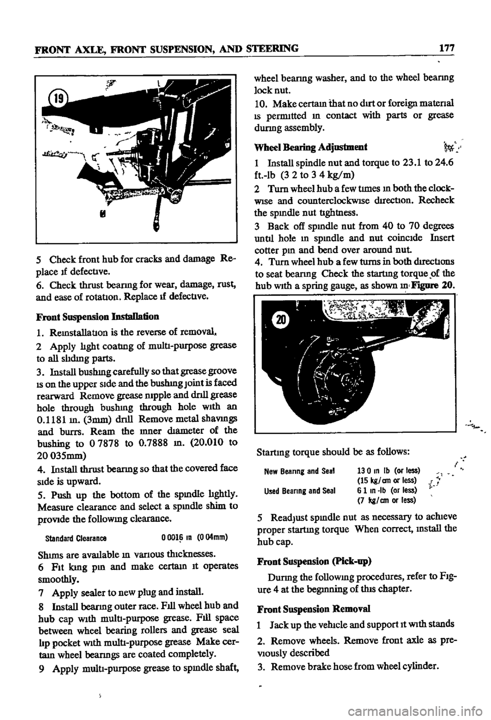
gauge
as
shown
Figure
20
Startmg
torque
should
be
as
follows
New
Beanng
and
Seal
130
In
Ib
or
less
15
kgl
an
or
less
i
Used
Beanng
and
Seal
6
1
In
Ib
or
less
7
kgl
an
or
less
5
ReadJust
spmdle
nut
as
necessary
to
achieve
proper
startmg
torque
When
correct
mstall
the
hub
cap
Front
Suspension
Pick
up
Durmg
the
followmg
procedures
refer
to
FIg
ure
4
at
the
begmning
of
this
chapter
Front
Suspension
Removal
1
Jack
up
the
vehicle
and
support
It
With
stands
2
Remove
wheels
Remove
front
axle
as
pre
Viously
described
3
Remove
brake
hose
from
wheel
cylinder
Page 192 of 252
CHAPTER
FOURTEEN
BRAKES
The
sedan
and
station
wagon
are
equipped
With
disc
brakes
on
the
front
wheels
drum
brakes
on
the
rear
wheeis
and
a
tandem
master
cyhnder
The
pIck
up
has
drum
brakes
on
all
four
wheels
and
a
single
master
cylmder
All
vehicles
have
a
mechanIcal
handbrake
that
works
on
the
rear
wheels
only
BRAKE
PEDAL
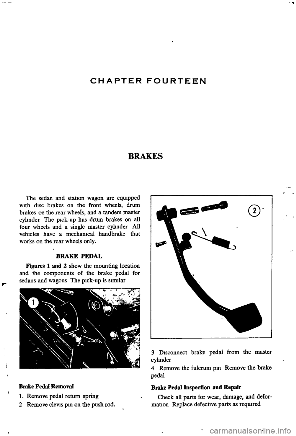
Figures
1
and
2
show
the
mounting
location
and
the
components
of
the
brake
pedal
for
sedans
and
wagons
The
pick
up
is
smlliar
Brake
Pedal
Removal
1
Remove
pedal
return
spring
2
Remove
cleViS
pm
on
the
push
rod
CD
3
Disconnect
brake
pedal
from
the
master
cyhnder
4
Remove
the
fulcrum
pm
Remove
the
brake
pedal
Brake
Pedal
Inspection
nnd
Repair
Check
all
parts
for
wear
damage
and
defor
matIon
Replace
defective
parts
as
reqwred
Page 193 of 252
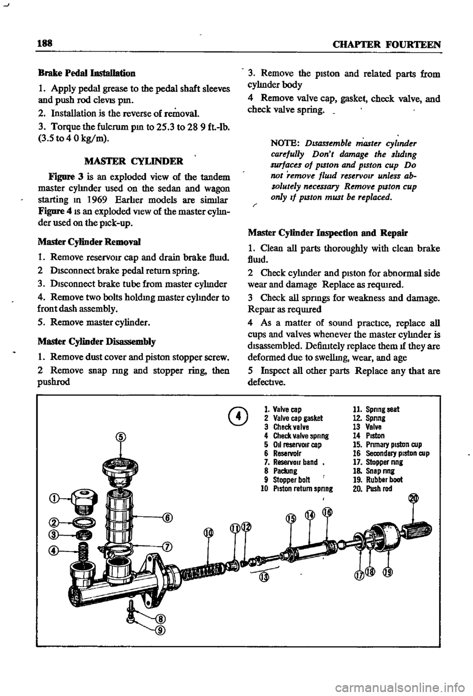
J
188
CHAPTER
FOURTEEN
Brake
Pedal
Installation
1
Apply
pedal
grease
to
the
pedal
shaft
sleeves
and
push
rod
cleVIS
pm
2
Installation
is
the
reverse
of
removal
3
Torque
the
fulcrum
pm
to
25
3
to
28
9
ft
lb
3
5
to
4
0
kg
m
MASTER
CYLINDER
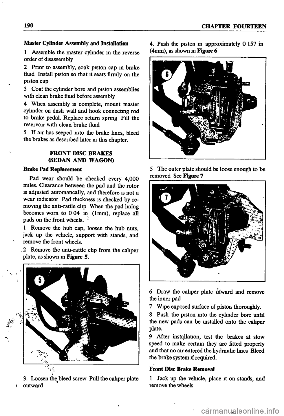
FIgure
3
is
an
exploded
view
of
the
tandem
master
cyhnder
used
on
the
sedan
and
wagon
starting
m
1969
Earher
models
are
sinnlar
Figure
4
IS
an
exploded
View
of
the
master
cyhn
der
used
on
the
pIck
up
Master
Cylinder
Removal
1
Remove
reservOIr
cap
and
drain
brake
f1wd
2
DISconnect
brake
pedal
return
spring
3
Disconnect
brake
tube
from
master
cyhnder
4
Remove
two
bolts
holdmg
master
cyhnder
to
front
dash
assembly
5
Remove
master
cylinder
Master
Cylinder
Disassembly
1
Remove
dust
cover
and
piston
stopper
screw
2
Remove
snap
nng
and
stopper
ring
then
pllShrod
3
Remove
the
piston
and
related
parts
from
cyhnderbody
4
Remove
valve
cap
gasket
check
valve
and
check
valve
spring
NOTE
DISassemble
master
cylmder
carefully
Don
t
damage
the
slldmg
surfaces
of
pISton
and
pISton
cup
Do
not
remove
flUId
reservOlT
unless
ab
solutely
necessary
Remove
pISton
cup
only
If
pISton
must
be
replaced
r
Master
Cylinder
Inspection
nnd
Repair
1
Clean
all
parts
thoroughly
with
clean
brake
fiwd
2
Check
cyhnder
and
piston
for
abnormal
side
wear
and
damage
Replace
as
reqUIred
3
Check
all
spnngs
for
weakness
and
damage
Reparr
as
reqUIred
4
As
a
matter
of
sound
practIce
replace
all
cups
and
valves
whenever
the
master
cyhnder
is
dISassembled
DefinItely
replace
them
1f
they
are
deformed
due
to
swellmg
wear
and
age
5
Inspect
all
other
parts
Replace
any
that
are
defective
CD
1
Valve
cap
2
Valve
cap
gasket
3
Check
valve
4
Check
valve
spnng
5
011
reservoIr
cap
6
Reservoir
7
ReservOir
band
8
Paclang
9
Stopper
bolt
10
PIston
return
spnng
11
Sprmg
seat
12
Spnng
13
Valve
14
PIston
15
Pnmary
pIston
cup
16
Secondary
piston
cup
17
Stopper
nng
18
Snap
nng
19
Rubber
boot
20
Push
rod
Page 195 of 252
190
CHAPTER
FOURTEEN
Master
Cylinder
Assembly
and
Installation
I
Assemble
the
master
cyhnder
m
the
reverse
order
of
dIsassembly
2
Pnor
to
assembly
soak
piston
cap
m
brake
flwd
Install
piston
so
that
It
seats
firmly
on
the
piston
cup
3
Coat
the
cyhnder
bore
and
pISton
assemblies
With
clean
brake
flwd
before
assembly
4
When
assembly
IS
complete
mount
master
cylmder
on
dash
wall
and
hook
connecting
rod
to
brake
pedal
Replace
return
sprmg
Fill
the
reservOir
With
clean
brake
flUid
5
If
aIr
has
seeped
mto
the
brake
Imes
bleed
the
brakes
as
descnbed
later
m
thIS
chapter
FRONT
DISC
BRAKES
SEDAN
AND
WAGON
Brake
Pad
Replacement
Pad
wear
should
be
checked
every
4
000
nuIes
Clearance
between
the
pad
and
the
rotor
IS
adjusted
automatIcally
and
therefore
IS
not
a
wear
mdlcator
Pad
thiCknesS
IS
checked
by
re
movmg
the
antI
rattle
clJp
When
the
pad
hning
becomes
worn
to
0
04
Imm
replace
all
pads
on
the
front
wheels
I
Remove
the
hub
cap
loosen
the
hub
nuts
jack
up
the
vehicle
support
with
stands
and
remove
the
front
wheels
2
Remove
the
antI
rattle
clJp
from
the
caliper
plate
as
shown
m
Figure
S
jty
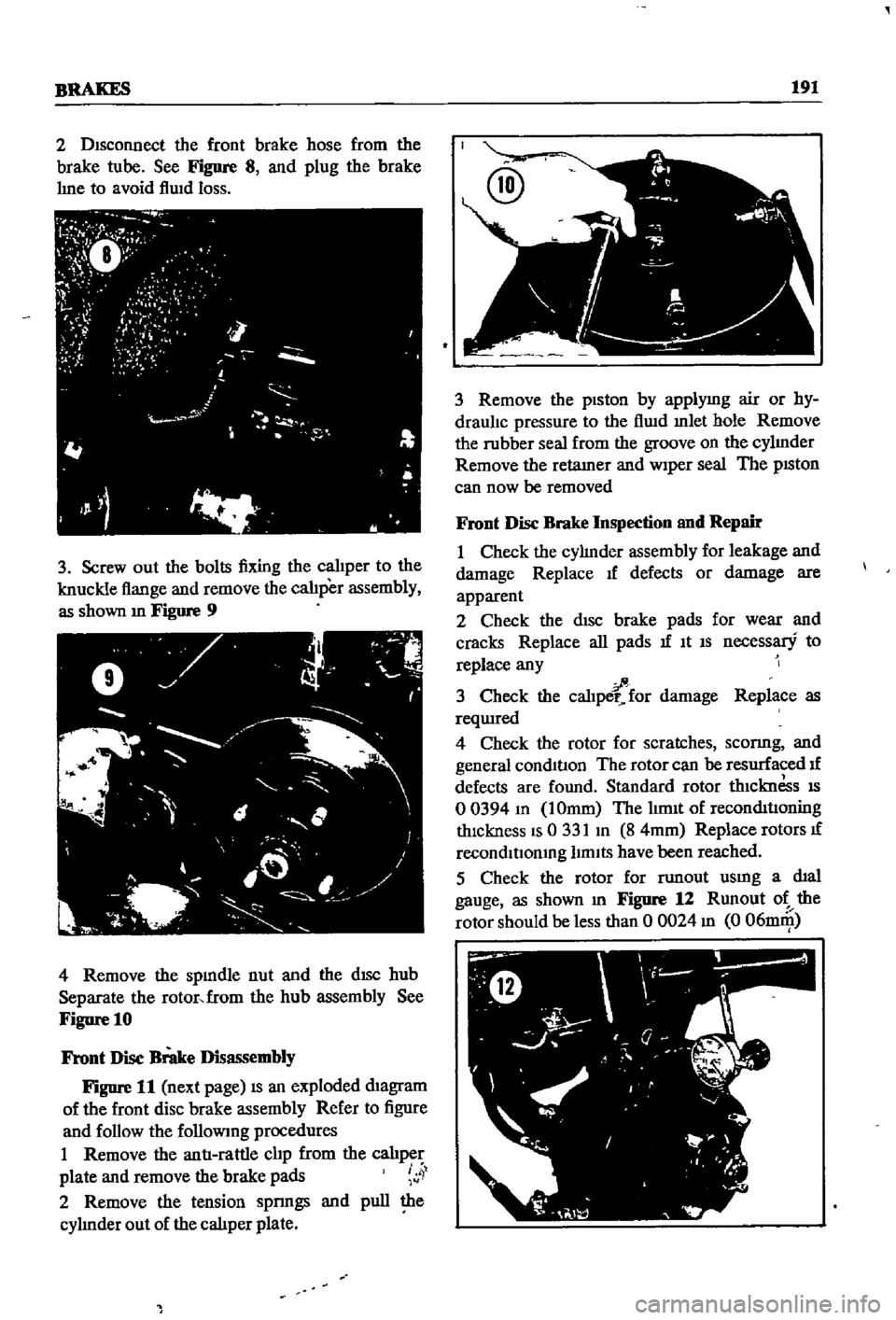
3
Loosen
the
bleed
screw
Pull
the
calJper
plate
outward
4
Push
the
pISton
m
approximately
0
157
in
4mm
as
shown
m
Figure
6
5
The
outer
plate
should
be
loose
enough
to
be
removed
See
Figure
7
6
Dra
y
the
calJper
plate
rlfward
and
remove
the
inner
pad
7
Wipe
exposed
surface
of
piston
thoroughly
8
Push
the
piston
mto
the
cyhnder
bore
untJI
the
new
pads
can
be
mstalled
onto
the
calJper
plate
9
After
instl
llatIon
test
the
brakes
at
slow
speed
to
make
certam
they
are
fitted
properly
and
that
no
au
entered
the
hydraul1c
hnes
Bleed
the
brake
system
If
required
Front
Disc
Brake
Removal
I
Jack
up
the
vehicle
place
It
on
stands
and
remove
the
wheels
P
Page 196 of 252
BRAKES
191
2
Disconnect
the
front
brake
hose
from
the
brake
tube
See
Figure
8
and
plug
the
brake
hne
to
avoid
flwd
loss
3
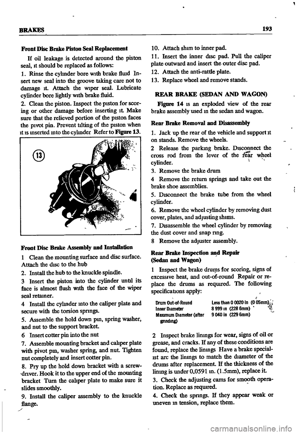
Screw
out
the
bolts
fixing
the
calJper
to
the
knuckle
flange
and
remove
the
calJper
assembly
as
shown
m
Figure
9
4
Remove
the
spmdle
nut
and
the
dISC
hub
Separate
the
rotor
from
the
hub
assembly
See
Figure
10
Front
Disc
Brake
Disassembly
Figure
11
next
page
IS
an
exploded
diagram
of
the
front
disc
brake
assembly
Refer
to
figure
and
follow
the
followmg
procedures
I
Remove
the
antI
rattle
clip
from
the
calJper
plate
and
remove
the
brake
pads
4
2
Remove
the
tension
spnngs
and
pull
the
cyhnder
out
of
the
caliper
plate
3
Remove
the
piston
by
applymg
air
or
hy
draulJc
pressure
to
the
flwd
mlet
hole
Remove
the
rubber
seal
from
the
groove
on
the
cyhnder
Remove
the
retamer
and
Wiper
seal
The
pISton
can
now
be
removed
Front
Disc
Brake
Inspection
and
Repair
I
Check
the
cyhnder
assembly
for
leakage
and
damage
Replace
If
defects
or
damage
are
apparent
2
Check
the
disc
brake
pads
for
wear
and
cracks
Replace
all
pads
If
It
IS
necessary
to
replace
any
fi
3
Check
the
caliper
for
damage
Replace
as
reqUIred
4
Check
the
rotor
for
scratches
sconng
and
general
conditIon
The
rotor
can
be
resurfaced
If
defects
are
found
Standard
rotor
thiCknesS
IS
o
0394
m
IOmm
The
hm1t
of
reconditIOning
thickness
IS
0
331
m
8
4mm
Replace
rotors
If
recondltIomng
limits
have
been
reached
5
Check
the
rotor
for
TWlout
usmg
a
dial
gauge
as
shown
m
Figure
12
Rnnout
ot
the
rotor
should
be
less
than
0
0024
m
0
06DlIll
Page 198 of 252
BRAKES
193
Front
Disc
Brake
Piston
Seal
Replacement
If
oil
leakage
is
detected
around
the
piston
seal
It
should
be
replaced
as
follows
I
Rinse
the
cyhnder
bore
With
brake
flwd
In
sert
new
seal
into
the
groove
taking
care
not
to
damage
It
Attach
the
wiper
seal
Lubricate
cylinder
bore
lightly
With
brake
fluid
2
Clean
the
piston
Inspect
the
pISton
for
scor
ing
or
other
damage
before
inserting
It
Make
sure
that
the
relieved
portion
of
the
pISton
faces
the
pivot
pin
Prevent
tilting
of
the
piston
when
It
IS
mserted
mto
the
cyhnder
Refer
to
Figure
13
@
4
Front
Disc
Brake
Assembly
and
Installation
I
Clean
the
mounting
surface
and
disc
surface
Attach
the
disc
to
the
hub
2
Install
the
hub
to
the
knuckle
spindle
3
Insert
the
piston
into
the
cylinder
untIl
its
face
is
almost
flush
With
the
face
of
the
wiper
seal
retamer
4
Install
the
cyhnder
mto
the
caliper
plate
and
secure
with
the
torsion
spnngs
5
Assemble
the
hold
down
pm
spring
washer
and
nut
to
the
support
bracket
6
Insert
cotter
pin
into
the
nut
7
Assemble
mounting
bracket
and
calJper
plate
with
pivot
pm
washer
spring
and
nut
Tighten
nut
completely
and
insert
cotter
pin
8
Pry
up
the
hold
down
bracket
with
a
screw
dnver
Hook
it
to
the
upper
end
of
the
mounting
bracket
Turn
the
cal1per
plate
to
make
sure
it
slides
smoothly
9
Install
the
caliper
assembly
to
the
knuckle
flange
10
Attach
shun
to
inner
pad
I
I
Insert
the
inner
dIsc
pad
Pull
the
caliper
plate
outward
and
insert
the
outer
disc
pad
12
Attach
the
anti
rattle
plate
13
Replace
wheel
and
remove
stands
REAR
BRAKE
SEDAN
AND
WAGON
Figure
14
IS
an
exploded
view
of
the
rear
brake
assembly
used
m
the
sedan
and
wagon
Rear
Brake
Removal
and
Disassembly
1
Jack
up
the
rear
of
the
vehicle
and
support
It
on
stands
Remove
the
wheels
2
Release
the
parkIng
brake
DISConnect
the
cross
rod
from
the
lever
of
the
ie
wheel
cylinder
3
Remove
the
brake
drum
4
Remove
the
return
springs
and
take
out
the
brake
shoe
assemblies
5
Disconnect
the
brake
tube
from
the
wheel
cylinder
6
Remove
the
wheel
cylinder
by
removing
dust
cover
plates
and
adJusting
shIms
7
DISassemble
the
wheel
cylinder
by
removing
the
dust
cover
and
snap
nng
8
Remove
the
adJuster
assembly
Rear
Brake
Inspection
d
Repair
Sedan
and
Wagon
I
Inspect
the
brake
druf
1s
for
scoring
signs
of
excessive
heat
and
out
of
round
Repair
or
re
place
the
drums
as
reqUIred
The
following
specificatIons
apply
Drum
Out
of
Round
Inner
Olameter
MaXImum
Diameter
after
IlI1ndmg
Less
than
0
0020
In
0
05mm
8
999
m
228
6mm
1
9040
In
229
6mm
2
Inspect
brake
limngs
for
wear
signs
of
oil
or
grease
and
cracks
If
any
of
these
conditions
are
found
replace
the
linmgs
Have
a
brake
special
ISt
arc
the
limngs
to
match
the
diameter
of
the
drums
after
replacement
If
the
thickness
of
the
limng
is
under
0
0591
m
1
5mm
replace
it
3
Check
the
adjusting
cams
for
smooth
opera
tion
Replace
as
reqUIred
4
Check
the
spnngs
If
they
appear
weak
or
uneven
m
tension
replace
them