1900 MITSUBISHI DIAMANTE steering
[x] Cancel search: steeringPage 174 of 408
DRIVEABILITYAND EMISSIONSCONTROL-S 4-31
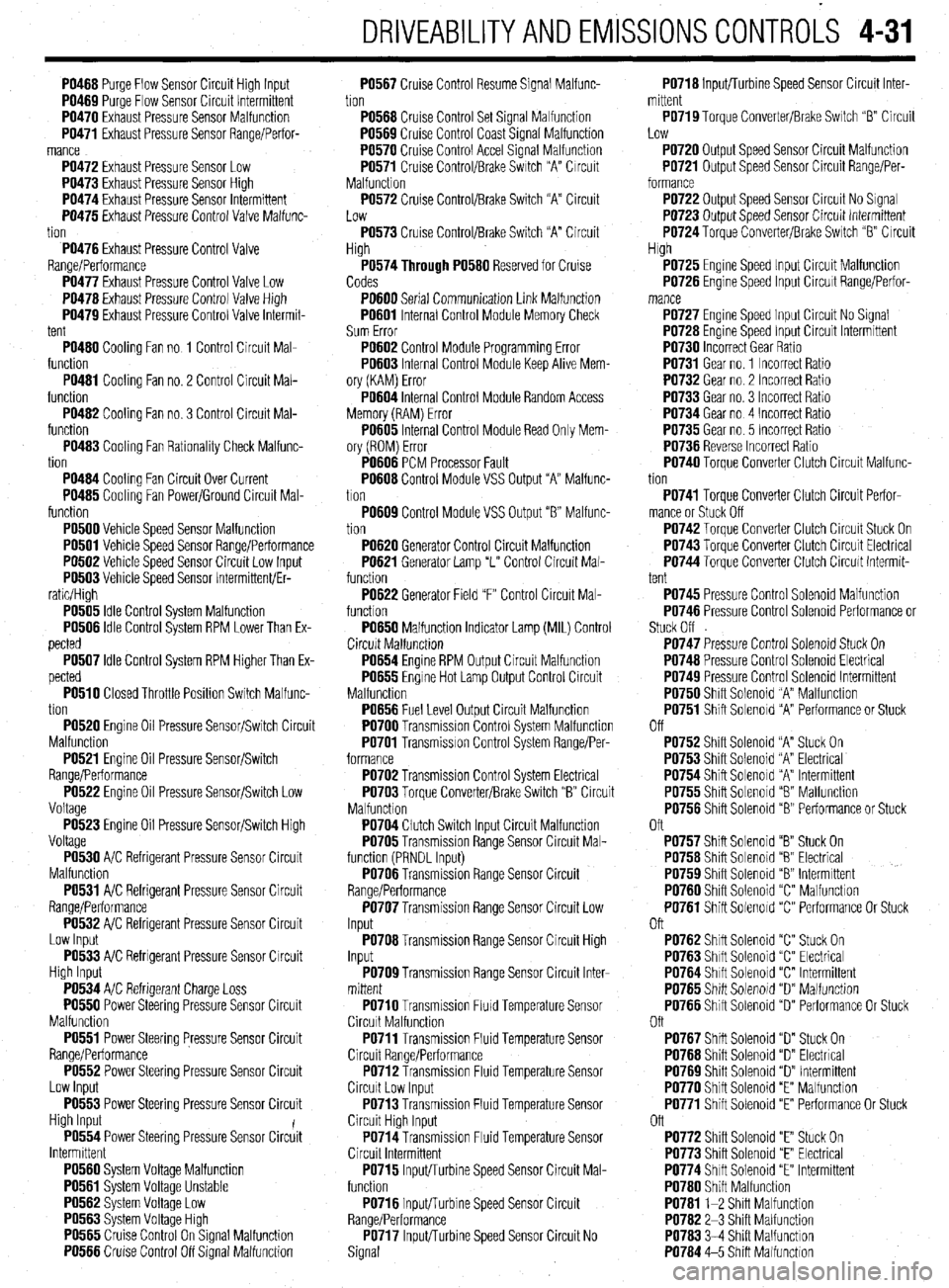
PO466 Purge Flow Sensor Circuit High Input
PO469 Purqe Flow Sensor Circuit Intermittent
PO470 Exhaust Pressure Sensor Malfunction
PO471 Exhaust Pressure Sensor Range/Perfor-
mance
PO472 Exhaust Pressure Sensor Low
PO473 Exhaust Pressure Sensor Hiah
PO474 Exhaust Pressure Sensor lnirmittent
PO475 Exhaust Pressure Control Valve Malfunc-
tion
PO476 Exhaust Pressure Control Valve
Range/Performance
PO477 Exhaust Pressure Control Valve Low
PO476 Exhaust Pressure Control Valve High
PO479 Exhaust Pressure Control Valve Intermit-
tent
PO460 Cooling Fan no 1 Control Circuit Mal-
function
PO461 Cooling Fan no. 2 Control Circuit Mal-
function
PO462 Cooling Fan no. 3 Control Circuit Mal-
function
PO463 Cooling Fan Rationality Check Malfunc-
tion
PO464 Cooling Fan Circuit Over Current
PO465 Cooling Fan Power/Ground Circuit Mal-
function
PO500 Vehicle Speed Sensor Malfunction
PO501 Vehicle Speed Sensor Range/Performance
PO502 Vehicle Speed Sensor Circuit Low Input
PO503 Vehicle Speed Sensor Intermittent/Er-
ratic/High
PO505 Idle Control System Malfunction
PO506 Idle Control System RPM Lower Than Ex-
pected
PO507 Idle Control System RPM Higher Than Ex-
pected
PO510 Closed Throttle Position Switch Malfunc-
tion
PO520 Engine Oil Pressure Sensor/Switch Circuit
Malfunction
PO521 Engine Oil Pressure Sensor/Switch
Range/Performance
PO522 Engine Oil Pressure Sensor/Switch Low
Voltage
PO523 Engine Oil Pressure Sensor/Switch High
Voltage
PO530 A/C Refrigerant Pressure Sensor Circuit
Malfunction
PO531 A/C Refrigerant Pressure Sensor Circuit
Range/Performance
PO532 A/C Refrigerant Pressure Sensor Circuit
Low Input
PO533 A/C Refrigerant Pressure Sensor Circuit
High Input
PO534 A/C Refrigerant Charge Loss
PO550 Power Steering Pressure Sensor Circuit
Malfunction
PO551 Power Steering Pressure Sensor Circuit
Range/Performance
PO552 Power Steering Pressure Sensor Circuit
Low Input
PO553 Power Steering Pressure Sensor Circuit
High Input
PO554 Power Steering Pressure Sensor Circiit
Intermittent
PO560 System Voltage Malfunction
PO561 System Voltage Unstable
PO562 System Voltage Low
PO563 Svstem Voltaoe Hlah
PO565 Ciuise Control On%ignal Malfunction
PO566 Cruise Control Off Signal Malfunction PO567 Cruise Control Resume Signal Malfunc-
tion
PO566 Cruise Control Set Signal Malfunction
PO569 Cruise Control Coast Signal Malfunction
PO570 Cruise Control Accel Signal Malfunction
PO571 Cruise Control/Brake Switch “A” Circuit
Malfunction
PO572 Cruise Control/Brake Switch “A” Circuit
Low
PO573 Cruise Control/Brake Switch “A” Circuit
High
P0574Through PO560 Reserved for Cruise
Codes
PO600 Serial Communication Link Malfunction
PO601 Internal Control Module Memory Check
Sum Error
PO602 Control Module Programming Error
PO603 Internal Control Module Keep Alive Mem-
ory (KAM) Error
PO604 Internal Control Module Random Access
Memory (RAM) Error
PO605 Internal Control Module Read Only Mem-
ory (ROM) Error
PO606 PCM Processor Fault
PO606 Control Module VSS Output “A” Malfunc-
tion
PO609 Control Module VSS Output “6” Malfunc-
tion
PO620 Generator Control Circuit Malfunction
PO621 Generator Lamp “L” Control Circuit Mal-
function
PO622 Generator Field “F” Control Circuit Mal-
function
PO650 Malfunction Indicator Lamp (MIL) Control
Circuit Malfunctron
PO654 Engine RPM Output Circuit Malfunction
PO655 Engine Hot Lamp Output Control Circuit
Malfunction
PO656 Fuel Level Output Circuit Malfunction
PO700 Transmission Control System Malfunction
PO701 Transmission Control System Range/Per-
formance
PO702 Transmission Control System Electrical
PO703 Torque Converter/Brake Switch “B” Circuit
Malfunction
PO704 Clutch Switch Input Circuit Malfunction
PO705 Transmission Range Sensor Circuit Mal-
function (PRNDL Input)
PO706 Transmission Range Sensor Circuit
Range/Performance
PO707 Transmission Range Sensor Circuit Low
Input
PO706 Transmission Range Sensor Circuit High
Input
PO709 Transmission Range Sensor Circuit Inter-
mittent
PO710 Transmission FluId Temperature Sensor
Circuit Malfunction
PO711 Transmission Fluid Temperature Sensor
Circuit Range/Performance
PO712 Transmission Fluid Temperature Sensor
Circuit Low Input
PO713 Transmission Fluid Temperature Sensor
Circuit High Input
PO714 Transmission Fluid Temperature Sensor
Circuit Intermittent
PO715 Input/Turbine Speed Sensor Circuit Mal-
function
PO716 Input/Turbine Speed Sensor Circuit
Range/Performance
PO717 InpWurbine Speed Sensor Circuit No
Signal PO716 Inputflurbine Speed Sensor Circuit Inter-
mittent
PO719 Torque Converter/Brake Switch “B” Circuit
Low
PO720 Output Speed Sensor Circuit Malfunction
PO721 Output Speed Sensor Circuit Range/Per-
formance
PO722 Output Speed Sensor Circuit No Signal
PO723 Output Speed Sensor Circuit Intermittent
PO724 Toraue Converter/Brake Switch “B” Circuit
High
PO725 Engine Speed Input Circuit Malfunction
PO726 Engine Speed Input Circuit Range/Perfor-
PO727 Engine Speed Input Circuit No Signal
PO726 Engine Speed Input Circuit Intermittent
PO730 Incorrect Gear Ratio
PO731 Gear no. 1 Incorrect Ratio
PO732 Gear no. 2 Incorrect Ratio
PO733 Gear no. 3 Incorrect Ratio
PO734 Gear no 4 Incorrect Ratio
PO735 Gear no. 5 Incorrect Ratio
PO736 Reverse Incorrect Ratio
PO740 Torque Converter Clutch Circuit Malfunc-
tion
PO741 Torque Converter Clutch Circuit Perfor-
mance or Stuck Off
PO742 Torque Converter Clutch Circuit Stuck On
PO743 Torque Converter Clutch Circuit Electrical
PO744 Torque Converter Clutch Circuit Intermit-
tent
PO745 Pressure Control Solenoid Malfunction
PO746 Pressure Control Solenoid Performance or
Stuck Off
PO747 Pressure Control Solenoid Stuck On
PO746 Pressure Control Solenoid Electrical
PO749 Pressure Control Solenoid Intermittent
PO750 Shift Solenoid “A” Malfunction
PO751 Shift Solenoid “A” Performance or Stuck
Off
PO752 Shift Solenoid “A” Stuck On
PO753 Shift Solenoid “A” Electrical
PO754 Shift Solenoid “A” Intermittent
PO755 Shift Solenoid “8 Malfunction
PO756 Shift Solenoid “B” Performance or Stuck
Oft
PO757 Shift Solenoid “B” Stuck On
PO756 Shift Solenoid “6” Electrical
PO759 Shift Solenoid “8” Intermittent
PO760 Shift Solenoid “C” Malfunction
PO761 Shift Solenoid “C” Performance Or Stuck
Oft
PO762 Shift Solenoid “C” Stuck On
PO763 Shift Solenoid “C” Electrical
PO764 Shift Solenoid “C” Intermittent
PO765 Shift Solenoid “D” Malfunction
PO766 Shift Solenoid “D” Performance Or Stuck
Oft
PO767 Shift Solenoid “D” Stuck On
PO766 Shift Solenoid “D” Electrical
PO769 Shift Solenoid “D” Intermittent
PO770 Shift Solenoid “E” Malfunction
PO771 Shift Solenoid “E” Performance Or Stuck
Off
PO772 Shift Solenoid “E” Stuck On
PO773 Shift Solenoid “E” Electrical
PO774 Shift Solenoid “E” Intermittent
PO760 Shift Malfunction
PO761 l-2 Shift Malfunction
PO762 2-3 Shift Malfunction
PO763 3-4 Shift Malfunction
PO764 4-5 Shift Malfunction
Page 197 of 408
5-10 FUELSYSTEM
1. _
Fuel tank pressure
-
relef vdive
REMOVAL &INSTALLATION
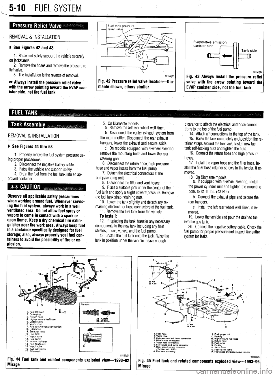
p See Figures 42 and 43
1. Raise and safely support the vehicle securely
on jackstands.
2. Remove the hoses and remove the pressure re-
lief valve.
3. The installation is the reverse of removal.
c, Always install the pressure relief valve
with the arrow pointing toward the EVAP can-
ister side, not the fuel tank 1 mame shown, others similar g3155g” Fig 42 Pressure relief valve location-llia
I I
Evaporatwe emlsslon
canister side
Tank side
+k
93155gt7 Fig. 43 Always install the pressure relief
valve with the arrow pointing toward the
EVAP canister side, not the fuel tank
REMOVAL&INSTALLATION
p See Figures 44 thru 58
1. Properly relieve the fuel system pressure us-
ing proper procedures.
2. Disconnect the negative battery cable.
3. Raise the vehicle and support safelv.
4. Drain the fuel from the fuel tank into an
ap- proved container.
Observe all applicable safety precautions
when working around fuel. Whenever servic-
ing the fuel system, always work in a well
ventilated area. Do not allow fuel spray or
vapors to come in contact with a spark or
open flame. Keep a dry chemical fire extin-
guisher near the work area. Always keep fuel
in a container specifically designed for fuel
storage; also, always properly seal fuel con-
tainers to avoid the possibility of fire or ex-
plosion.
5. On Diamante models:
a. Remove the left rear wheel well liner.
b Disconnect the center exhaust system from
the main muffler. Disconnect the rear exhaust
hangers, lower the exhaust and secure aside.
c. On models equipped with 4-wheel steering,
remove the mounting bolts and lower the rear
steering gear.
6. Disconnect the return hose, high pressure
hose and vapor hoses from the fuel pump.
7. Detach the electrical connectors at the
pump/sending unit.
8. Disconnect the filler and vent hoses.
s
9. Place a suitable jack under the center of the
fuel tank and apply a slight upward pressure. Remove
the fuel tank strap retaining nuts.
10. Lower the tank slightly and detach any re-
maining electrical or hose connectors at the fuel tank.
11. Remove the fuel tank from the vehicle.
To install: 12. If replacing the tank, transfer any necessary
components to the new tank including any heat
shields, hoses, valves, and the fuel pump.
13. Install the fuel tank onto the jack. Rarse the
tank in position under the vehicle. Leave enough
Tg. 44 Fuel tank and related components exploded view-1990-92
mirage
clearance to attach the electrical and hose connec-
tions to the top of the fuel pump.
14. Attach all connectrons to the top of the tank.
15. Raise the tank completely and position the re-
tainer straps around the fuel tank. Install new fuel
tank self-locking nuts and tighten the nuts.
16. Connect the return hose and high pressure
hoses.
17. Install the vapor hose and the filler hose. In-
stall the filler hose retainer screws to the fender, if re-
moved.
18. On Diamante models:
a. If equipped with 4-wheel steering, install
the power cylinder unit and tighten the mounting
bolts to 31 ft. Ibs. (43 Nm).
b. Connect the exhaust pipe and secure the
rear hangers.
c. Install the left rear wheel well liner, if re-
moved.
19. Lower the vehicle and pour the drained fuel
into the gas tank.
20. Connect the negative battery cable. Check the
fuel pump for proper pressure and inspect the entire
system for leaks.
:ig. 45
vlirage Fuel tank and related 93155(12E components exploded view-1993-96
Page 212 of 408
CHASSIS ELECtRldAL 6-9
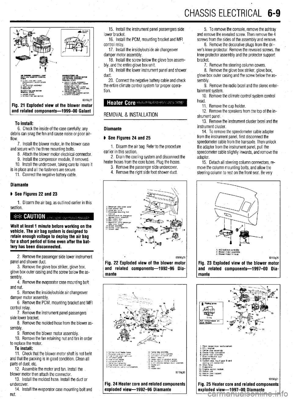
93156g27 Fig. 21 Exploded view of the blower motor
and related components-1999-00 Galant
To install:
6. Check the inside of the case carefully; any
debris can snag the fan and cause noise or poor air-
flow.
7. Install the blower motor, in the blower case
and secure with the three mounting bolts,
8. Attach the blower motor electrlcal connector,
9. Install the compressor module, if removed.
10. Install the undercover, takmg care to insure it
is in place and all the fasteners are secure.
11. Connect the negative battery cable.
Diamante
u See Figures 22 and 23
1. Disarm the air bag, as outlined earlier in this
section.
Wait at least 1 minute before working on the
vehicle. The air bag system is designed to
retain enough voltage to deploy the air bag
for a short period of time even after the bat-
tery has been disconnected.
2. Remove the passenger side lower instrument
panel and shower duct,
3. Remove the glove box striker, glove box,
glove box outer casing and the screw below the as-
sembly.
4. Remove the evaporator case mounting bolt
and nut.
5. Remove the inside/outside air changeover
damper motor assembly.
6 Remove the PCM, mounting bracket and MFI
control relay.
7. Remove the instrument panel passengers
side lower bracket.
8. Remove the molded hose from the blower as-
sembly.
9. Remove the blower motor assembly.
10. Remove the fan retaining nut and fan in order
to replace the motor,
To install: 11. Check that the blower motor shaft is not bent
and that the packing is in good condition, Clean all
parts of dust, etc.
12. Assemble the motor and fan. Install the
blower motor then attach the connector.
13. Install the molded hose. Install the duct or
undercover.
14. Install the evaporator case mounting bolt and
nut. 15. Install the instrument panel passengers side
lower bracket.
16. Install the PCM, mounting bracket and MFI
control relay.
17. Install the inside/outside air changeover
damper motor assembly.
18. Install the screw below the glove box assem-
bly, and the entire glove box unit.
19. Install the lower instrument panel and shower
duct.
20. Connect the negative battery cable and check
the entire climate control system for proper opera-
tion.
REMOVAL & INSTALLATION
Diamante
u See Figures 24
and 25
1. Disarm the air bag Refer to the procedure
earlier in this section.
2. Dram the cooling system and disconnect the
heater hoses from the core tubes. Plug the hoses.
3. Remove the passenger side undercover.
4. Remove the right side foot shower duct. 5. To remove the console, remove the ashtray
and remove the revealed screw. Then remove the 4
screws from the sides of the assembly and remove.
6. Remove the decorative plugs from the drl-
ver’s knee protector. Remove the revealed screws, the
knee protector assembly and the protector support
bracket.
7. Remove the steering column covers.
8. Remove the glove box striker, glove box,
glove box outer casing and the screw below the as-
sembly.
9. Remove the radio bezel and the stereo enter-
tainment system.
10. Remove the climate control system control
head.
11. Remove the cup holder.
12. Remove the speakers from the top of the in-
strument panel.
13. Remove the instrument cluster bezel and the
instrument cluster.
14. To remove the speedometer cable adapter
from the instrument panel, first disconnect the
speedometer cable from the transaxle. Then unlock
the adapter from the instrument panel, pull the
speedometer cable slightly inwards, and remove the
adapter
15. Detach all steering column connectors, re-
move the column mounting bolts, and allow the
steering column to rest on the front seat. Be very
Fig. 23 Exploded view of the blower motor
and related components-1997-00 Dia-
Fig. 25 Heater core and related components
exploded view-1997-00 Diamante
Page 213 of 408
640 CHASSIS ELECTRICAL
careful not to allow anything to come in contact with
the air bag unit.
16. Remove the glove box lamp assembly.
17. Remove the remaining instrument panel
mounting screws and remove the instrument panel
from the vehicle.
18. Remove the left side foot shower ductwork,
lap cooler duct and center duct.
19. Remove the front and center reinforcements
and center stay assembly.
20. Remove the air distribution duct assembly.
21. Detach all connectors from heater-box-
mounted items.
22. Remove the heater box mounting screws and
nut, then remove the unit from the vehicle.
23. Disassemble on a workbench. Remove the
heater core from the heater case.
To install:
24. Thoroughly clean and dry the inside of the
case and install the heater core and all related parts.
25. Install the heater unit to the vehicle and install
the mounting screws and nut. Be sure the evaporator
case and heater case are fitted together properly. At-
tach all connectors to heater-box-mounted items.
26. Install the air distribution duct assembly. In-
stall the front and center reinforcements and center
stay assembly.
27. Install the center duct, lap cooler duct and left
side foot shower duct.
28. Install the instrument panel and mounting
screws.
29. Install the glove box lamp assembly.
30. Secure the steering column and attach all
steering column connectors.
31. Install the speedometer cable adapter to the
instrument panel.
32. Install the instrument cluster and the instru-
ment cluster bezel.
33. Install the speakers to the top of the instru-
ment panel.
34. Install the cup holder.
35. Install the climate control system control
head.
36. Install the stereo entertainment system and
bezel.
37. Install the screw below the glove box assem-
bly, and the entire glove box unit.
38. Install the steering column covers.
39. Install the knee protector support bracket, the
protector and the decorative plugs.
40. Install the console and the ashtray. 41. Install the right side foot shower duct.
42. Install the passenger side undercover.
43. Connect the heater hoses to the core tubes.
44. Fill the cooling system.
45. Connect the negative battery cable and check
the entire climate control system for proper operation
and leaks.
Galant
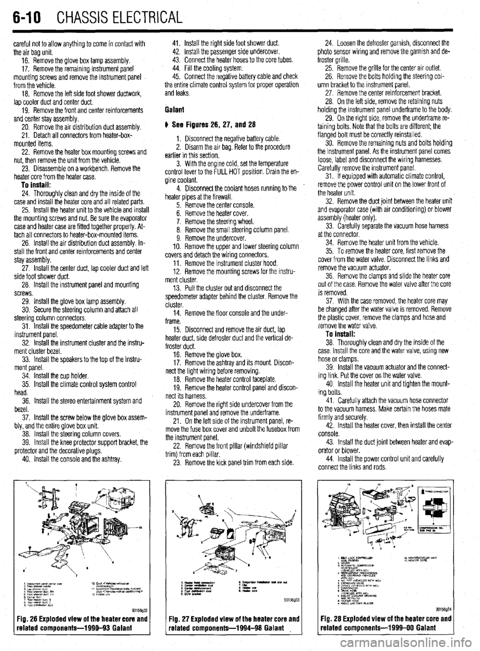
# See Figures 26, 27, and 28
1. Disconnect the negative battery cable.
2. Disarm the air bag. Refer to the procedure
earlier in this section.
3. With the engine cold, set the temperature
control lever to the FULL HOT position. Drain the en-
gine coolant.
4. Disconnect the coolant hoses running to the
heater pipes at the firewall.
5. Remove the center console.
6. Remove the heater cover.
7. Remove the steering wheel.
8. Remove the small steering column panel.
9. Remove the undercover.
10. Remove the upper and lower steering column
covers and detach the wiring connectors.
11. Remove the instrument cluster hood.
12. Remove the mounting screws for the instru-
ment cluster.
13. Pull the cluster out and disconnect the
speedometer adapter behind the cluster. Remove the
cluster.
14. Remove the floor console and the under-
frame.
15. Disconnect and remove the air duct, lap
heater duct, side defroster duct and the vertical de-
froster duct.
16. Remove the glove box.
17. Remove the ashtray and its mount. Discon-
nect the light wiring before removing.
18. Remove the heater control faceplate.
19. Remove the heater control panel and discon-
nect its harness.
20. Remove the right side undercover from the
instrument panel and remove the underframe.
21. On the left side of the instrument panel, re-
move the fuse box cover and unbolt the fusebox from
the instrument panel.
22. Remove the front pillar (windshield pillar
trim) from each pillar.
23. Remove the kick panel trim from each side.
Fig. 26 Exploded view of the heater core and
related components-1990-93 Galant
:IQ. 27 Exploded view of the heater core and
-elated components-1994-98 Galant 24. Loosen the defroster garnish, disconnect the
photo sensor wiring and remove the garnish and de-
froster grille.
25. Remove the grille for the center air outlet.
26. Remove the bolts holding the steering col-
umn bracket to the instrument panel.
27, Remove the center reinforcement bracket.
28. On the left side, remove the retaining nuts
holding the instrument panel underframe to the body.
29. On the right side, remove the underframe re-
taining bolts. Note that the bolts are different; the
flanged bolt must be correctly reinstalled.
30. Remove the remaining nuts and bolts holding
the instrument panel. As the instrument panel comes
loose, label and disconnect the wiring harnesses.
Carefully remove the instrument panel.
31. If equipped with automatic climate control,
remove the power control unit on the lower front of
the heater unit.
32. Remove the duct joint between the heater unit
and evaporator case (with air conditioning) or blower
assembly (heater only).
33. Carefully separate the vacuum hose harness
at the connector.
34. Remove the heater unit from the vehicle.
35. To remove the heater core, first remove the
cover from the water valve. Disconnect the links and
remove the vacuum actuator.
36. Remove the clamps and slide the heater core
out of the case. Remove the water valve after the core
is removed.
37. With the case removed, the heater core may
be changed after the water valve is removed. Remove
the plastic cover, remove the clamps and hose and
remove the water valve.
To install:
38. Thoroughly clean and dry the inside of the
case. Install the core and the water valve, using new
hose or clamps.
39. Install the vacuum actuator and the connect-
ing link. Put the cover on the water valve.
40. Install the heater unit and tighten the mount-
ing bolts.
41. Carefully attach the vacuum hose connector
to the vacuum harness. Make certain the hoses mate
firmly and securely.
42. Install the heater cover, then install the center
console.
43. Install the duct joint between heater and evap-
orator or blower.
44. Install the power control unit and carefully
connect the links and rods.
Fig. 28 Exploded view of the heater core and
related components-1999-00 Galant
Page 214 of 408
CHASSIS ELECTRICAL 6-11
45. Install the heater hoses under the hood.
46. Install the mstrument panel by reversing its
removal procedure.
47. Install the center console.
48. install the upper and lower steering column
covers.
49. Install the center panel undercover.
50. Install the small column panel.
51. Install the steering wheel.
52. Fill the cooling system.
53. Connect the negative battery cable and check
the entire climate control system for proper operation
and leaks.
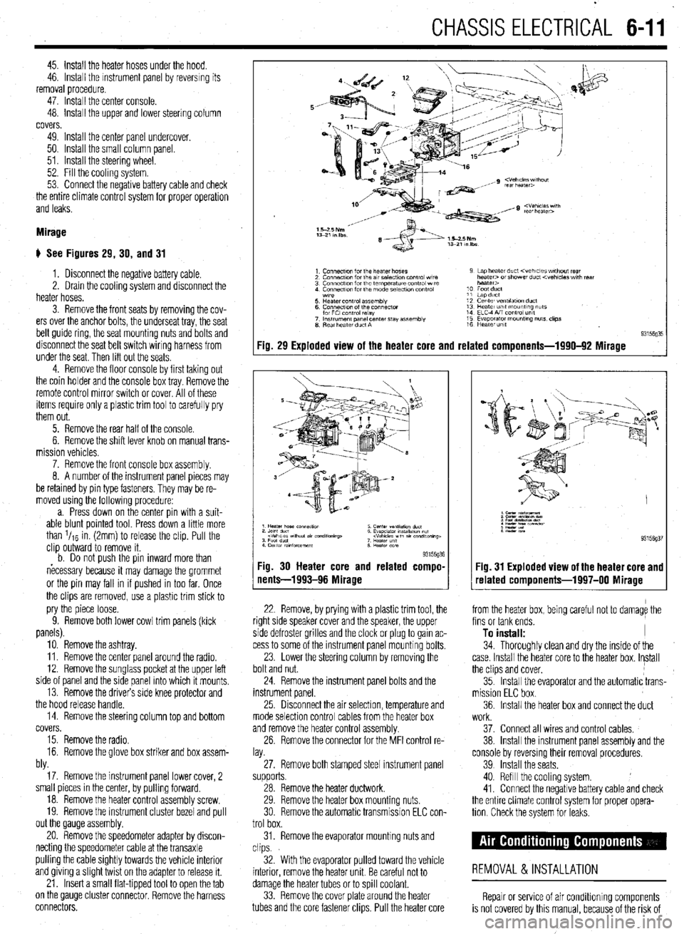
Mirage
# See Figures 29, 30, and 31
1. Disconnect the negative battery cable.
2. Drain the cooling system and disconnect the
heater hoses.
3. Remove the front seats by removing the cov-
ers over the anchor bolts, the underseat tray, the seat
belt guide ring, the seat mounting nuts and bolts and
disconnect the seat belt switch wiring harness from
under the seat. Then lift out the seats
4. Remove the floor console by first taking out
the coin holder and the console box tray. Remove the
remote control mirror switch or cover. All of these
items require only a plastic trim tool to carefully pry
them out.
5. Remove the rear half of the console.
6. Remove the shift lever knob on manual trans-
mission vehicles.
7. Remove the front console box assembly.
8. A number of the instrument panel pieces may
be retamed by pin type fasteners. They may be re-
moved using the following procedure:
a. Press down on the center pin with a suit-
able blunt pointed tool. Press down a little more
than l/re in. (2mm) to release the clip. Pull the
clip outward to remove it.
b. Do not oush the oin inward more than
necessary because it may damage the grommet
or the pin may fall in if pushed in too far. Once
the clips are removed, use a plastic trim stick to
pry the piece loose.
9. Remove both lower cowl trim panels (kick
panels).
10. Remove the ashtray.
11. Remove the center panel around the radio.
12. Remove the sunglass pocket at the upper left
side of panel and the side panel into which it mounts,
13. Remove the drivers side knee protector and
the hood release handle.
14. Remove the steering column top and bottom
covers.
15. Remove the radio.
16. Remove the glove box striker and box assem-
bly.
17. Remove the instrument panel lower cover, 2
small pieces in the center, by pulling forward.
18. Remove the heater control assembly screw.
19. Remove the instrument cluster bezel and pull
out the Qauge assembly.
20. Remove the speedometer adapter by discon-
necting the speedometer cable at the transaxle
pulling the cable Sightly towards the vehicle interior
and giving a Slight twist on the adapter to release it.
21. Insert a small flat-tipped tool to open the tab
on the QauQe cluster connector. Remove the harness
connectors.
Fig. 29 Exploded view of the heater core and related components-1990-92 Mirage
93l%Q% Fig. 30 Heater core and related compo-
nents-1993-96 Mirage
22. Remove, by prying with a plastic trim tool, the
right side speaker cover and the speaker, the upper
side defroster grilles and the clock or plug to gain ac-
cess to some of the instrument panel mounting bolts.
23. Lower the steering column by removing the
bolt and nut.
24. Remove the instrument panel bolts and the
instrument panel.
25 Drsconnect the air selection, temperature and
mode selection control cables from the heater box
and remove the heater control assembly.
26. Remove the connector for the MFI control re-
lay.
27. Remove both stamped steel instrument panel
supports.
28. Remove the heater ductwork.
29. Remove the heater box mounting nuts.
30 Remove the automatic transmission ELC con-
trol box.
31. Remove the evaporator mounting nuts and
clips.
32. With the evaporator pulled toward the vehicle
interior, remove the heater unit. Be careful not to
damage the heater tubes or to spill coolant.
33. Remove the cover plate around the heater
tubes and the core fastener clips. Pull the heater core 34. Thoroughly clean and dry the inside of the
case. Install the heater core to the heater box. Install
the clips and cover,
35. Install the evaporator and the automatic trans-
mission ELC box.
36. Install the heater box and connect the duct
Fig. 31 Exploded view of the heater core and
related components-1997-00 Mirage
from the heater box, being careful not to damage the
fins or tank ends.
To install: I
work.
37. Connect all wires and control cables,
38. Install the instrument panel assembly and the
console by reversmg their removal procedures.
39 Install the seats.
40. Refill the cooling system.
41. Connect the negative battery cable and check
the entire climate control system for proper opera-
tion Check the system for leaks.
REMOVAL &INSTALLATION
Repair or service of air Conditioning components
is not covered by this manual, because of the risk of
Page 216 of 408
CHASSIS ELECTRICiL 6-13
.
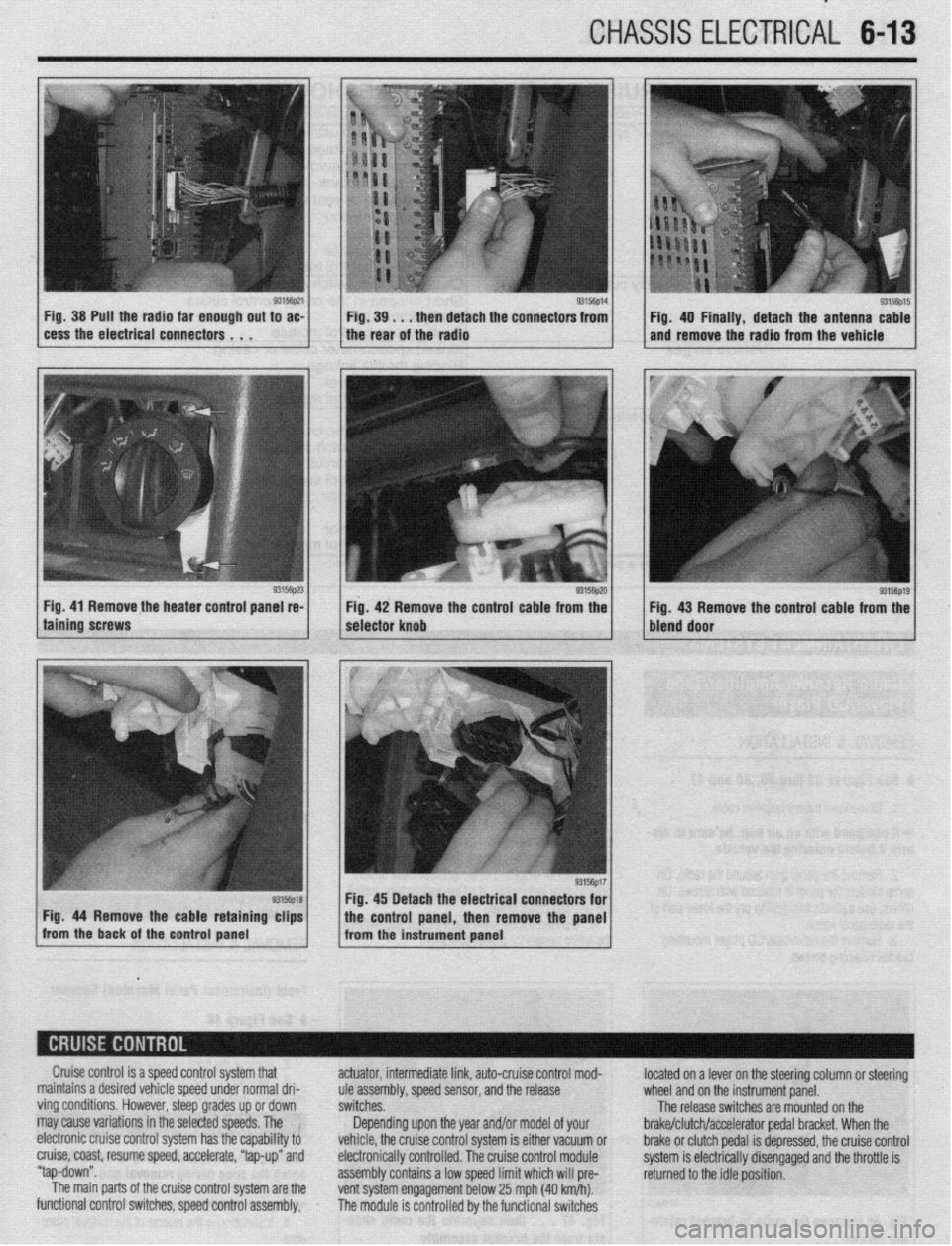
Fig. 38 Pull the radia far enough out to ac-
cess the electrical connectors . . . 9315fip14 Fig. 39. . . then detach the connectors from
I I Fig. 40 Finally, detach the antenna cable
the rear of the radio and remove the radio from the vehicle
Fig. 41 Remove the heater control panel re-
Fig. 42 Remove the control cable from the
g3156p1g / Fig 43 Remove the control cable from the
bleid door
Cruise control is a speed control system that
maintains a desired vehicle speed under normal dri-
ving conditions. However, steep grades up or down
may cause variations in the selected speeds. The !
electronic cruise control system has the capability to
cruise, coast, resume speed, accelerate, “tap-up” and
“tap-down”.
The main parts of the cruise control system are the
functional control switches, speed control assembly, actuator, intermediate link, auto-cruise control mod-
ule assembly, speed sensor, and the release
switches.
Depending upon the year and/or model of your
vehicle, the cruise control system is either vacuum or
electronically controlled. The cruise control module
assembly contains a low speed limit which will pre-
vent system engagement below 25 mph (40 km/h).
The module is controlled by the functional switches located on a lever on the steering column or steering
wheel and on the instrument panel.
The release switches are mounted on the
brake/clutch/accelerator pedal bracket. When the
brake or clutch pedal is depressed, the cruise control
system is electrically disengaged and the throttle is
returned to the idle position.
Page 221 of 408
.
6-18 CHASSIS ELECTRICAL
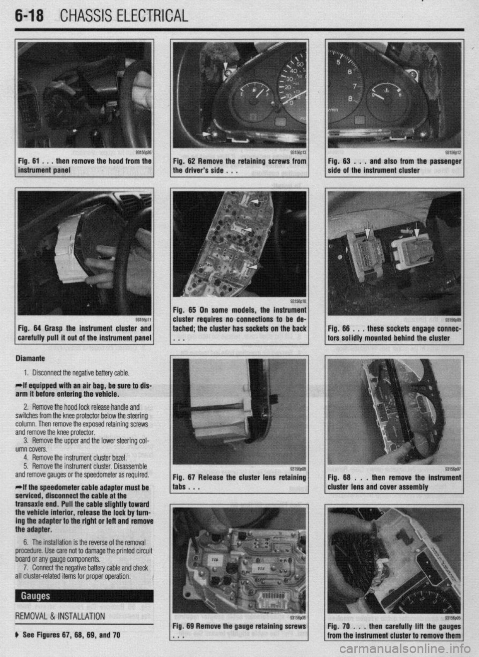
Fig. 64 Grasp the instrument cluster and
carefully pull it out of the instrument panel tached; the cluster has sockets on the back Fig. 66 . , .
these sockets engage connec-
tors solidly mounted behind the cluster
Diamante
1. Disconnect the negative battery cable.
*If equipped with an air bag, be sure to dis-
arm it before entering the vehicle.
2. Remove the hood lock release handle and
switches from the knee protector below the steering
column. Then remove the exposed retaining screws
and remove the knee protector.
3. Remove the upper and the lower steering col-
umn covers.
4. Remove the instrument cluster bezel.
5. Remove the instrument cluster. Disassemble
and remove gauges or the speedometer as required.
*If the speedometer cable adapter must be
serviced. disconnect the cable at the
transaxle end. Pull the cable slightly toward
the vehicle interior, release the lock by turn-
ing the adapter to the right or left and remove
the adapter.
6. The installation is the reverse of the removal
procedure. Use care not to damage the printed circuit
board or any gauge components,
7. Connect the negative battery cable and check
all cluster-related items for proper operation.
REMOVAL &INSTALLATION
I
b See Figures 67, 66, 69, and 70
83156pD6 Fig. 69 Remove the gauge retaining screws Fig. 70 . . . then carefully lift the gauges
from the instrument cluster to remove them
Page 222 of 408
CHASSIS ELECTRICAL 6-19
1. Disconnect the negative battery cable.
are all built into 1 multi-function combination
2. Remove the instrument cluster, as outlined 1. Disconnect the negative battery cable.
earlier in this section. switch that is mounted on the steering col-
2. Using a small screwdriver or other suitable
umn. Refer to Section 8 for procedures re-
3. Remove the retaining screws for the instrument tool, carefully pry the retaining clips from either side
garding the combination switch.
cluster lens and cover assembly. Remove the cover of the switch trim plate.
3.
and lens. Carefully pull the switch and trim plate out of
,
4. Remove the retaining screws for the gauge or the instrument panel.
4. Detach the electrical connectors and remove
warning lamp to be replaced, then remove the gauge
the switch.
or warning lamp.
REMOVAL&INSTALLATION : 5. The installation is the reverse of removal.
To install:
5. Place the gauge or warning lamp into place
and tighten the retaining screws. 1. Disconnect the negative battery cable.
6. Install the instrument cluster lens and cover 2. Using a suitable prytool, disengage the switch
assembly. retaining tabs.
REMOVAL &INSTALLATION 7. Install the instrument cluster. 3. Gently pull the switch from the instrument
8. Connect the negative battery cable. panel.
4. Detach the electrical connector and remove the *On all models the headlights, turn signals,
switch. and on some models, the cruise control func-
5. The installation is the reverse of removal. tion are all built into 1 multi-function combi-
nation switch that is mounted on the steerinq
REMOVAL &INSTALLATION column. Refer to Section 8 for procedures 6
garding the combination switch.
*The headlights, turn signals, dimmer
switch, horn switch, windshield
REMOVAL &INSTALLATION
wiper/washer, intermittent wiper switch and *
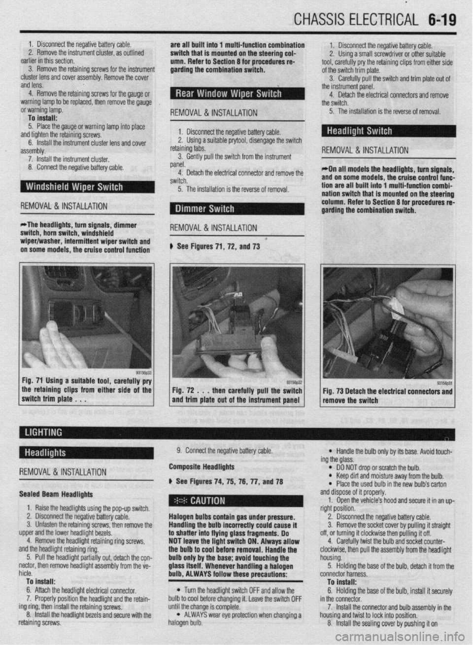
on some models, the cruise control function # See Figures 71, 72, and 73
the retaining clips from either side of the
switch trim plate . . . Fig. 72 . . . then carefully pull the switch
and trim plate out of the instrument panel Fig. 73 Detach the electrical connectors and
remove the switch
-
REMOVAL &INSTALLATION
Sealed Beam Headlights
1. Raise the headlights using the pop-up switch.
2. Disconnect the negative battery cable.
3. Unfasten the retaining screws, then remove the
upper and the lower headlight bezels.
4. Remove the headlight retaining ring screws,
and the headlight retaining ring.
5. Pull the headlight partially out, detach the con-
nectar, then remove headlight assembly from the ve-
hicle.
To install:
6. Attach the headlight electrical connector.
7. Properly position the headlight and the retain-
ing ring, then install the retaining screws.
8. Install the headlight bezels and secure with the
retaining screws. 9. Connect the negative battery cable.
Composite Headlights
6 See Figures 74, 75, 76, 77, anU78
Halogen bulbs contain gas under pressure.
Handling the
bulb incorrectly could cause it
to shatter into flying glass fragments. Do
NOT leave the light switch ON. Always allow
the bulb to cool before removal. Handle the
bulb only by the base; avoid touching the
glass itself. Whenever handling a halogen
bulb, ALWAYS follow these precautions:
l Turn the headlight switch OFF and allow the
bulb to cool before changing it. Leave the switch OFF
until the change is complete.
l ALWAYS wear eye protection when changing a
halogen bulb.
l Handle the bulb only by its base. Avoid touch-
ing the glass.
l DO NOT drop or scratch the bulb. l Keep dirt and moisture away from the bulb.
* Place the used bulb in the new bulb’s carton
and dispose of it properly.
1. Open the vehicle’s hood and secure it in an up-
right position.
2. Disconnect the negative battery cable.
3. Remove the socket cover by pulling it straight
off, or turning it clockwise then pulling it off.
4. Carefully twist the bulb and socket counter-
clockwise, then pull the assembly from the headlight
housing.
5. Holding the base of the bulb, detach it from the
connector harness.
To install:
6. Holding the base of the bulb, install it securely
in the connector.
7. Install the connector and bulb assembly in the
housing and twist to lock into position.
8. Install the sealing cover by pushing it on