1900 MITSUBISHI DIAMANTE steering
[x] Cancel search: steeringPage 87 of 408
3-26 ENGINEANDENGINEOVERHAUL
18. Remove the self-locking nuts and the small
retaining bolt holding the exhaust pipe to the bottom
of the exhaust manifold. Separate the pipe from the
manifold and remove the gasket.
19. Remove the bolts holding the support brace
to the bottom of the intake manifold.
20. Use the special hex wrench (MB 998051-01)
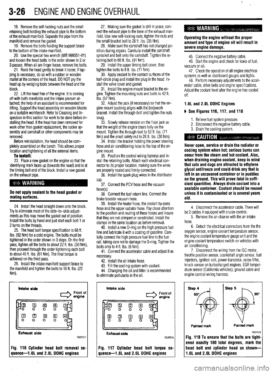
and loosen the head bolts in the order shown in 2 or
3 passes. When all are finger loose, remove the bolts.
21. Rock the head gently to break it loose; if tap-
ping is necessary, do so with a rubber or wooden
mallet at the corners of the head. DO NOT pry the
head up by wedging tools between the head and the
block.
22. Lift the head free of the engine. It is coming
off with both manifolds and the intake plenum at-
tached; the help of an assistant is recommended for
lifting. Support the head assembly on wooden blocks
on a suitable workbench. Refer to Cleaning and In-
spection in this section for work to be done before in-
stalling the head. If the head has been removed for
work other than gasket replacement, the rocker as-
sembly and camshaft or other components may be
removed.
Before reinstallation, the head should be com-
pletely assembled on the bench. This allows proper
location and tightening of all the external items.
To install: 23. Place a new gasket on the engine so that the
identifying mark faces up (towards the head) and is at
the timing belt end of the block. Install a new gasket
on the exhaust pipe.
Do not apply sealant to the head gasket or
mating surfaces.
24. Install the head straight down onto the block.
Try to eliminate most of the side-to-side adjust-
ments as this may move the gasket out of position.
Install the bolts by hand and just start each bolt 1 or
2 turns on the threads.
25. The head bolt torque specification is 68 ft.
Ibs. (92 Nm) for a cold engine. The bolts must be
tightened in the order shown in 3 steps. On the first
pass, tighten all the bolts to about 22 ft. Ibs. (30 Nm),
then proceed through the order tightening each bolt
to about 45 ft. Ibs. (61 Nm). The final torque is
achieved on the third pass.
26. Install the intake manifold support brace to
the manifold and tighten the bolts to 16 ft. Ibs. (22
Nm). 27. Making sure the gasket is still in place, con-
nect the exhaust pipe to the base of the exhaust man-
ifold. Use new self-locking nuts; tighten the nuts and
the small bracket bolt to 26 ft. Ibs. (35 Nm).
28. Make sure the camshaft has not changed po-
sition during repalrs. Carefully install the camshaft
sprocket and belt onto the camshaft. Tighten the re-
taining bolt to 66 ft. Ibs. (91 Nm).
29. Install the upper timing belt cover, then
tighten the bolts to 8 ft. Ibs. (11 Nm).
30. Apply sealant to the contact surfaces of the
half-circle plug and install the plug in the head In-
stall the valve cover and gasket.
31. Install the engine mount bracket to the en-
gine. Tighten the mounting nuts and bolts to 42 ft.
Ibs. (57 Nm).
32. Adjust the jack (if necessary) so that the en-
gine mount bushing aligns with the bodywork
bracket. Install the through-bolt and tighten the nuts
snug.
33. Slowly release tension on the floor jack so
that the weight of the engine bears fully on the
mount. Tighten the through-bolt to 52 ft. Ibs. (71
Nm) and the small safety nut to 26 ft. tbs. (36 Nm).
34. Install the bracket holding the power steering
hose and air conditioning hose to the top of the en-
gine mount.
35. Position the control wiring harness and in-
stall the retaining bolts. Attach each electrical con-
nector to its proper location, making sure the wires
are properly routed and firmly connected.
36. Install the spark plug wires in the distributor
cap.
37. Connect the PCV hose and the vacuum
hose(s).
38. Connect the fuel return line. Connect the
brake booster vacuum hose.
39. Install the heater hose, the coolant by-pass
hose and.the upper radiator hose. Pay close attention
to the position and routing of these hoses and insure
that they are not crimped or constricted. Install the
clamps in the same location as before removal.
40. Install a new O-ring on the high pressure fuel
line and lubricate it with a coating of gasoline. Care-
fully connect the high pressure fuel line to the fuel
rail, taking care not to damage the O-ring. Tighten the
bolts only to 4 ft. Ibs. (6 Nm).
41. Connect the accelerator cable and adjust it as
necessary.
42. Install the air intake hose.
43. Fill the cooling system with coolant.
44. Changing the oil and filter is recommended
to eliminate pollutants in the oil.
Intake side
I Front of
engine
Exhaust side
Fig. 116 Cylinder head bolt removal se-
quence-l .6L and 2.OL DDHC engines intake
side
Front of
entine
Exhaust side 7923PG18
Fig. 117 Cylinder head bolt torque se-
quence-l .6L and 2.OL DDHC engines Operating the engine without the proper
amount and type of engine oil will result in
severe engine damage.
45. Connect the negative battery cable.
46. Start the engine and check for leaks of fuel,
vacuum or oil.
47. Check the operation of all engine electrical
systems as well as dashboard gauges and lights.
48. Perform necessary adjustments to the accel-
erator cable, drive belts and engine specifications.
Adjust the coolant level after the engine has cooled
Off.
1.6L and 2.OL DDHC Engines
ti See Figures 116,117, and 116
1. Relieve fuel system pressure.
2. Disconnect the negative battery cable.
3. Drain the cooling system.
Never open, service or drain the radiator or
cooling system when hot; serious burns can
occur from the steam and hot coolant. Also,
when draining engine coolant, keep in mind
that cats and dogs are attracted to ethylene
glycol antifreeze and could drink any that is
left in an uncovered container or in puddles
on the ground. This will prove fatal in suffi-
cient quantities. Always drain coolant into a
sealable container. Coolant should be reused
unless it is contaminated or is several years
old.
4. Disconnect the accelerator cable. There will
be 2 cables if equipped with cruise-control.
5. Remove the air cleaner with the air intake
hose.
6. Detach the electrical connectors from the the
oxygen sensor, engine coolant temperature sensor,
the engine coolant temperature gauge unit and the
engine coolant temperature switch on vehicles with
air conditioning.
7. Disconnect the wiring from the ISC motor,
throttle position sensor, crankshaft angle sensor, fuel
injectors, ignition coil, power transistor, noise filter,
knock sensor on turbocharged engines, EGR temper-
ature sensor (California vehicles), ground cable and
engine control wiring harness.
Painted mark Painted mark
Fig. 116 To ensure that the bolts are tight-
ened exactly 160 total degrees, mark the
11.6L and 2.OL DDHC engines head bolt and cylinder head as shown-
Page 89 of 408
3-28 ENGINEANDENGINEOVERHAUL
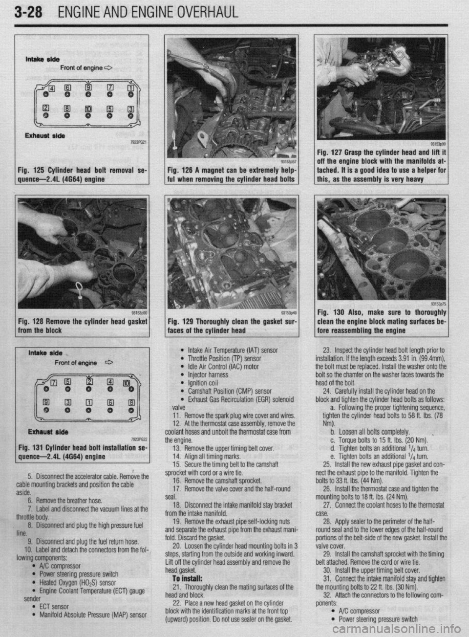
lntsltaelde Front of engine c3
Fig. 125 Cylinder head bolt removal se- Fig. 127 Grasp the cylinder head and lift it
off the engine block with the manifolds at-
ig. 126 A magnet can be extremely help- tached. It is a good idea to use a helper for
quence-2.41(4664) engine I ful when removing the cylinder head bolts 1 1 this, as the assembly is very heavy
93153pOO Fig. 128 Remove the cylinder head gasket 33153p4!3 Fig, 129 Thoroughly clean the gasket sur- Fig. 130 Also, make sure to thoroughly
clean the engine block mating surfaces be-
from the block
faces of the cylinder head fore reassembling the engine
l Intake Air Temperature (IAT) sensor l Throttle Position (TP) sensor
: /I;%;,; rZ;Z;;(lAC) motor 23. Inspect the cylinder head bolt length prior to
installation. If the length exceeds 3.91 in. (99.4mm),
the bolt must be replaced. Install the washer onto the
bolt so the chamfer on the washer faces towards the
l Ignition coil head of the bolt. l Camshaft Position (CMP) sensor 24. Carefully install the cylinder head on the l Exhaust Gas Recirculation (EGR) solenoid block and tighten the cylinder head bolts as follows:
valve a. Following the proper tightening sequence,
11. Remove the spark plug wire cover and wires. tighten the cylinder head bolts to 58 ft. Ibs. (78
12. At the thermostat case assembly, remove the Nm).
coolant hoses and unbolt the thermostat case from b. Loosen all bolts completely.
the engine. c. Torque bolts to 15 ft. Ibs. (20 Nm). ’
Fig. 131 Cylinder head bolt installation se-
13. Remove the upper timing belt cover d. Tighten bolts an additional 1/4 turn.
14. Align all timing marks. e. Tighten bolts an additional 1/4 turn.
15. Secure the timina belt to the camshaft 25. Install the new exhaust pipe aasket and con-
iliiL.-
5.
9. Disconnect and plug the fuel return hose. Disconnect the accelerator cable. Remove the
cable mounting brackets and position the cable
10. Label and detach the connectors from the fol- aside.
lowing components: 6. Remove the breather hose.
* A$ compressor
* Power steering pressure switch ‘7. Label and disconnect the vacuum lines at the
* Heated Oxygen (HO$) sensor tree body.
* Engine Coolant Temperature (ECT) gauge . 8. D&connect and plug the high pressure fuel
sender
lint3
l
ECT sensor l Manifold Absolute Pressure (MAP) sensor sprocket with cord or a wire tie.
fold. Discard the gasket, 16. Remove the camshaft sprocket.
20. Loosen the cylinder head mounting bolts in 3 17.
steps, starting from the outside and working inward. Remove the valve cover and the half-round
seal.
Lift off the cylinder head assembly and remove the 18. Disconnect the intake manifold stay bracket
head gasket.
To install: from the intake manifold.
21. Thoroughly clean the mating surfaces of the 19. Remove the exhaust pipe self-locking nuts
head and block. and separate the exhaust pipe from the exhaust mani-
22. Place a new head gasket on the cylinder
block with the identification marks at the front top
(upward) position. Do not use sealer on the gasket. nect the exhaust pipe to the manifold. Tighten the
portions of the belt-side of the new gasket. Install thr bolts to 33 ft. Ibs. (44 Nm).
valve cover. 26.
29. Install the thermostat case and tighten the
Install the camshaft sprocket with the timing mounting bolts to 18 ft. Ibs. (24 Nm).
belt attached. Remove the cord or wire tie.
30. Install the upper timing belt cover. 27. Connect the coolant hoses to the thermostat
31. Connect the intake manifold stay and tighten case.
the mounting bolts to 22 ft. Ibs. (30 Nm). 28.
32. Attach the connectors to the following com- Apply sealer to the perimeter of the half-
round seal and to the lower edges of the half-round
ponents: l A/C compressor l Power steering pressure switch
Page 90 of 408
ENGINEANDENGINEOVERHAUL 3-29
l HOzS sensor l ECT gauge sender l ECT sensor l MAP sensor l IAT sensor l TP sensor l IAC motor l injector harness l ignition coil l CMP sensor l EGR solenoid valve
33. Install the spark plug wires and cover,
34. Replace the O-rings and connect the fuel
lines.
35. Install the air cleaner and intake hose. Con-
nect the breather hose.
36. Fill the cooling system.
37. Connect the negative battery cable
3.01 DDHC Engine
ti See Figures 132 and 133
1. Relieve fuel system pressure. Disconnect the
negative battery cable.
2. Drain the cooling system.
Never open, service or drain the radiator or
cooling system when hot; serious burns can
occur from the steam and hot coolant. Also,
when draining engine coolant, keep in mind
that cats and dogs are attracted to ethylene
glycol antifreeze and could drink any that is
left in an uncovered container or in puddles
on the ground. This will prove fatal in suffi-
cient quantltles. Always drain coolant into a
sealable container. Coolant should be reused
unless it is contaminated or is several years
old.
3. Remove the air intake hoses.
4. Remove air intake plenum and intake mani-
fold.
5. Remove the exhaust manifold.
6. Remove the timing belt. Refer to the timing
belt procedure in this section.
7. Remove the breather hose.
8. Remove the spark plug wire center cover and
remove the spark plug wires.
9. Remove the rocker covers.
10. Remove the intake camshaft sprockets.
11. Remove the rear timing belt cover.
12. Remove the ignition coil assembly.
13. Disconnect all water hoses from the thermo-
stat housing and remove the housing.
14. Disconnect the water inlet from the front
head.
15. Loosen the cylinder head mounting bolts in
the reverse of the torque sequence and loosen the
bolts in three steps. Lift off the cylinder head assem-
bly and remove the head gasket.
To install: 16. Thoroughly clean the sealing surfaces of the
head and block.
17. Place a new head gasket on the cylinder
block with the identification marks in the front top
(upward) position. Do not use sealer on the gasket,
18. Carefully install the cylinder head on the
block. Be sure the head bolt washers are installed
with the chamfered edge upward. Using three even
steps, torque the head bolts in sequence, to 76-83 ft.
Ibs. (105-115 Nm).
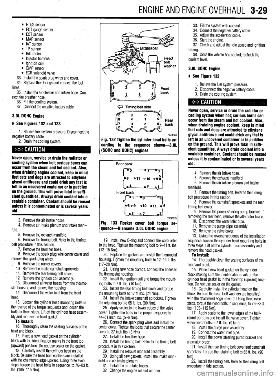
@ Timing belt side
7923PG26 :ig. 132 Tighten the cylinder head bolts ac-
:ording to the sequence shown-3.01
SDHC and DDHC) engines
Rear bank
[::od
04
~8 01
Front bank
'1 "8
509 010 011 6
1.03 07 02 7923ffi25 Fig. 133 Rocker cover bolt torque se-
quence-Diamante 3.OL DDHC engine
19. Install new O-ring and connect the water inlet
to the head. Tighten the mounting bolt to 9-11 ft. Ibs
(12-15 Nm).
20. Replace the gaskets and install the thermostat
housing. Tighten the mounting bolts to 12-14 ft. Ibs.
(17-20 Nm).
21. Using new hose clamps, connect the hoses to
the thermostat housing.
22. Install the Ignition coil and torque the mount-
ing bolts to 7 ft. Ibs. (10 Nm).
23. Install the rear timing belt cover and torque
the mounting bolts to 17 ft. Ibs. (24 Nm).
24. Install the intake camshaft sprockets. Tighten
the retaining bolt to 65 ft. Ibs. (90 Nm).
25. Apply sealer to the lower edges of the valve
cover. Tighten the bolts in the proper sequence to
44-51 inch Ibs. (5-6 Nm).
26. Connect the spark plug wires and install the
center cover. Tighten the bolts that secure the center
cover to 27 inch Ibs. (3 Nm)
27. Install the breather hose.
28. Install the timing belt. Refer to the timing belt
procedure in this section,
29. Install the exhaust manifold assembly.
30. Using all new gaskets, install the intake man-
ifold and air intake plenum.
31. Install the air intake hoses.
32. Change the engine oil and oil filter. 33. Fill the system wrth coolant.
34. Connect the negabve battery cable.
35. Adjust the accelerator cable.
36. Start the engine.
37. Check and adjust the idle speed and ignition
timing.
38. Once the vehicle has cooled, recheck the
coolant level.
3.OL SDHC Engine
# See Figure 132
1. Relieve the fuel system pressure.
2. Disconnect the negative battery cable.
3. Drain the cooling system.
Never open, service or drain the radiator or
cooling system when hot; serious burns can
occur from the steam and hot coolant. Also,
when draining engine coolant, keep in mind
that cats and dogs are attracted to ethylene
alvcol antifreeze and could drink any that is
Left in an uncovered container or in puddles
on the ground. This will Drove fatal in suff i-
cient quantities. Always drain coolant into a
sealable container. Coolant should be reused
Unless it is Contaminated or is several years
old.
4. Remove the air intake hose.
5. Remove the exhaust manifold.
6. Remove the air intake plenum and intake
manifold.
7. Remove the timing belt. Refer to the timing
belt procedure in this section.
8. Remove the camshaft sprockets and the rear
timing belt cover.
9. Remove the power steering pump bracket. If
removing the rear head, remove the alternator brace.
10. Disconnect the water inlet pipe.
11. Remove the purge pipe assembly.
12. Remove the valve cover,
13. Using the reverse sequence of the installation
sequence, loosen the cylinder head mounting bolts in
three steps. Lift off the cylmder head assembly and
remove the head gasket.
To install: 14. Thoroughly clean the sealing surfaces of the
head and block.
15. Place a new head gasket on the cylinder
block making sure the identification mark on the
cylrnder head gasket is in the front top (upward) loca-
tion. Do not use sealer on the gasket,
16. Carefully install the cylinder head on the
block. Be sure the head bolt washers are installed
with the chamfered edge upward. Using three even
steps, torque the head bolts in sequence, to 7683 ft.
Ibs. (105-115 Nm).
17. Apply sealer to the lower edges of the half-
round portions and install the valve cover. Tighten
valve cover bolts to 7 ft. Ibs. (9 Nm).
18. Install the purge pipe assembly.
19. Connect the water inlet pipe.
20. Install the power steering pump bracket and
alternator brace.
21. Install the rear timing belt cover and camshaft
sprockets. Torque the retaining bolt to 65 ft. Ibs. (90
Nm).
22. Install the timing belt. Refer to the timing belt
procedure in this section.
Page 101 of 408
l
3-40 ENGINEANDENGINEOVERHAUL
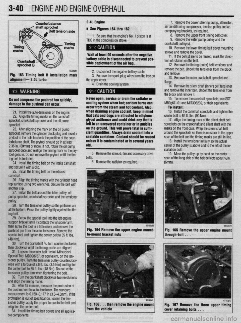
Counterbaiance
19235861
Fig. 163 Timing belt 5 installation mark
alignment- 2.OL turbo
Do not compress the pushrod too quickly,
damage to the pushrod can occur.
21. Install the auto-tensioner on the engine.
22. Align the timing marks on the camshaft
sprocket, crankshaft sprocket and the oil pump
sprocket.
23. After aligning the mark on the oil pump
: sprocket, remove the cylinder block plug and insert a
prytool in the hole to check the position of the coun-
terbalance shaft. The orvtool should ao in at least 7. Remove the power steering pump, alternator
air conditioning compressor, tension pulley and ac-
companying brackets, as required.
8 Remove the upper front timing belt cover.
9. Remove the water pump pulley and the
crankshaft pulley(s).
10. Remove the lower timing belt cover mountinf
screws and remove the cover.
11. If the belt(s) are to be reused, mark the direc.
tion of rotation on the belt.
12. Remove the timing (outer) belt tensioner and
remove the belt. Unbolt the tensioner from the block
and remove.
13. Remove the outer crankshaft sprocket and
flange.
14. Remove the silent shaft (inner) belt tensioner
and remove the inner belt. Unbolt the tensioner from
the block and remove it.
15. To remove the camshaft sprockets, use SST
Ml39g67-01 and MlT308239, or their equivalents.
To in!3tall:
16. Install the camshaft sprockets and tighten thr
center bolt to 65 ft. Ibs. (90 Nm).
17. Align the timing mark of the silent shaft belt
sprockets on the crankshaft and silent shaft with the
marks on the front case. Wrap the silent shaft belt
around the sprockets so there is no slack in the uppe
!
I span of the belt and the timing marks are still in line.
18. Install the tensioner initially so the actual
:enter of the pulley is above and to the left of the in-
jtallation bolt. 2.36 in. (60mm) or more, if not, rotai;! the oil pump
sprocket once and realign the timing mark so the pry-
24. Install the timing belt on the intake camshaft
and secure it with a clip. .
25. Install the timina belt on the exhaust old. 2.41 Engine
I: # See Figures 164 thru 162
1. Be sure that the engine’s No. 1 piston is at
TDC in the compression stroke.
Wait at least 90 seconds after the negative
battery cable is disconnected to prevent pos-
sible deployment of the air bag.
2. Disconnect the negative battery cable.
3. Remove the spark plug wires from the tree on
the upper cover.
4. Drain the cooling system.
Never open, service or drain the radiator or
cooling system when hot; serious bums can
occur from the steam and hot coolant. Also,
when draining engine coolant, keep in mind
that cats and dogs are attracted to ethylene
glycol antifreeze and could drink any that is
left in an uncovered container or in puddles
on the ground. This will prove fatal in suffi-
cient quantities. Always dram coolant into a
sealable container. Coolant should be reused
unless it is contaminated or is several years
tool goes in. Do not remove the on/ool until the tfrn- 5. Remove the shroud, fan and accessory drive
ing belt is installed. lelts.
6. Remove the radiator as required. 19. Move the pulley up by hand so the center
jpan of the lona side of the belt deflects about 11~ in.
camshaft.
26. Align the timing marks with the cylinder head
top surface using two wrenches. Secure the belt with
another clip.
27. tnstatf the belt around the idler pulley, oil
pump sprocket, crankshaft sprocket and the tensioner
pulley.
28. Turn the tensioner pulley so the pinholes are
at the bottom. Press the pulley lightly against the tim-
ing belt.
29. Screw the special tool into the left engine
support bracket until it contacts the tensioner arm,
then screw the tool in a little more and remove the
pushrod pin from the auto-tensioner. Remove the
special tool and tighten the center bolt to 35 ft. Ibs.
(48 Nm). Fig 164 Remove the upper engine mount-
to-mount bracket nuts al%@]
Pm3p70 Fig. 165 Remove the upper engine mount
through-bolt . . .
30. Turn the crankshaft ‘Id turn counterclockwise,
then clockwise until the timing marks are aligned.
31. Loosen the center bolt. Install Mitsubishi
Special Tool MD998767, or equivalent, on the ten-
sioner p&y. Turn the tensioner pulley counterclock-
wise with a torque of 2.6 ft. Ibs. (3.5 Nm) and tighten
the center boftto 35 ft. tbs. (48 Nm). Do not let the
tensioner pUtFey turn when tightening the bolt.
32. Turn the crankshaft clockwise two revolutions
and align the timing marks.
33. After 15 minutes, measure the protrusion of
the pushrod on the auto-tensioner. The standard
measurement is 0.150-0.177 in (3.8-4.5mm). If the
I protrusion is out of specification, loosen the ten-
I sioner pulley, apply the proper torque to the belt and
: retighten the center bolt.
34. Install the timing belt covers and all applica-
i ble components.
Page 103 of 408
.
3-42 ENGINEANDENGINEOVERHAUL
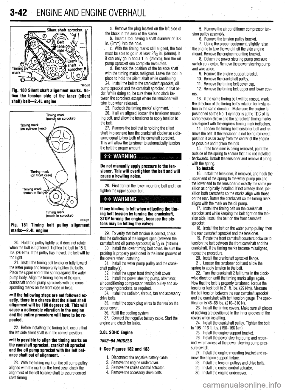
Fig. 180 Silent shaft alignment marks. No,
tice the tension side of the inner (silen
shaft) belt-2.41 enaine
Timing merk
(pun+ on sprocket)
liming m&k
(notch in sprocket)
79245g31 :ig. 181 Timing belt pulley alignmenl
narks-2.41 enoine
20. Hold the pulley tightly so it does not rotate
when the bolt is tlghtened. Tighten the bolt to 15 ft.
Ibs. (20 Nm). If the pulley has moved, the belt will be
too tight
21. Install the timing belt tensioner fully toward
the water pump and temporarily tighten the bolts.
Place the upper end of the spring against the water
pump body. Align the timing marks of the cam,
crankshaft and oil pump sprockets with the corre-
sponding marks on the front case or head.
*If the following steps are not followed ex-
actly, there is a chance that the silent shaft
alignment will be 180 degrees off. This will
cause a noticeable vibration in the engine
and the entire procedure will have to be re-
peated.
22. Before installing the timing belt, ensure that
the left side silent shaft is in the correct position.
*It is possible to align the timing marks on
the camshaft sprocket, crankshaft sprocket
and the oil pump sprocket with the lefl bal-
ance shaft out of alignment.
23. With the timing mark on the oil pump pulley
aligned with the mark on the front case, check the
alignment of the left balance shaft to assure correct
shaft timing. a. Remove the plug located on the left side of
the block in the area of the starter.
b. Insert a tool having a shaft diameter of 0.3
in. (8mm) into the hole.
c. With the timing marks still aligned, the tool
must be able to go in at least 2l/s in. (59mm). If
it can only go m about 1 in. (25mm), turn the oil
pump sprocket one complete revolution.
d. Recheck the position of the balance shaft
with the timing marks reahgned. Leave the tool in
place to hold the silent shaft while continuing.
24. Install the belt to the crankshaft sprocket, oil
pump sprocket and the camshaft sprocket, in that or-
der. While doing so, be sure there is no slack be-
tween the sprockets except where the tensioner will
take it up when released.
25. Recheck the timing marks’ alignment.
26. If all are aligned, loosen the tensioner mount-
ing bolt, and allow the tensioner to apply tension to
the belt.
27. Remove the tool that is holding the silent
shaft in place and turn the crankshaft clockwise a dis-
tance equal to two teeth of the camshaft sprocket.
This will allow the tensioner to automatically tension
the belt the proper amount.
Do not manually apply pressure to the ten-
sioner. This will overtighten the belt and will
cause a howling noise.
28. First tighten the lower mounting bolt and then
tighten the upper spacer bolt.
If any binding is felt when adiustino the tim-
ing delt tension by turning th;! crankshaft,
STOP turning the engine, because the pis-
tons may be hitting the valves.
29. To verify that belt tension is correct, check
that the deflection of the longest span (between the
camshaft and oil pump sprockets) is I/* in. (13mm).
30. Install the lower timing belt cover. Be sure the
packing is properly positioned in the inner grooves of
the covers when installing.
31. Install the water pump pulley and the crank-
shaft pulley(s).
32. Install the upper front timing belt cover.
33. Install the power steering pump, alternator,
air conditioning compressor, tension pulley and ac-
companying brackets, as required.
34. Install the radiator, shroud, fan and accessory
drive belts.
35. Install the spark plug wires to the tree on the
upper cover.
36. Refill the cooling system.
37. Connect the negative battery cable. Start the
engme and check for leaks.
3.OL SDHC Engine
1992-94 MODELS
# See Figures 182 and 183
1. Disconnect the negative battery cable.
2. Remove the engine undercover
3. Remove the cruise control
actuator 4. Remove the accessory drive belts. 5. Remove the air conditioner compressor ten-
sion pulley assembly.
6. Remove the tension pulley bracket.
7. Using the proper equipment, slightly raise
the engine to take the weight off the side engine
mount. Remove the engine mounting bracket.
8. Detach the power steering pump pressure
switch connector. Remove the power steering pump
and wire aside.
9. Remove the engine support bracket.
10. Remove the crankshaft pulley.
11. Remove the timing belt cover cap.
12. Remove the timing belt upper and lower cov-
ers.
13. If the same timing belt will be reused, mark
the direction of the timing belt’s rotation for installa-
tion in the same direction. Make sure the engine is
positioned so the No. 1 cylinder is at the TDC of its
compression stroke and the sprockets’ timing marks
are aligned with the engine’s timing mark indicators.
14. Loosen the timing belt tensioner bolt and re-
move the belt. If the tensioner is not being removed,
position it as far away from the center of the engine
as possible and tighten the bolt.
15. If the tensioner is being removed, paint the
outside of the spring to ensure that it is not installed
backwards. Unbolt the tensioner and remove it along
with the spring.
To install:
16. Install the tensioner, if removed, and hook the
upper end of the spring to the water pump pin and
the lower end to the tensioner in exactly the same po-
sition as originally installed. If not already done, po-
sition both camshafts so the marks align with those
on the rear. Rotate the crankshaft so the timing mark
aligns with the mark on the oil pump.
17. Install the timing belt on the crankshaft
sprocket and while keeping the belt tight on the ten-
sion side, install the belt on the front camshaft
sprocket.
18. Install the belt on the water pump pulley, then
the rear camshaft sprocket and the tensioner.
19. Rotate the front camshaft counterclockwise to
tension the belt between the front camshaft and the
crankshaft. If the tlmlng marks became misaligned,
repeat the procedure.
20. Install the crankshaft sprocket flange.
21. Loosen the tensioner bolt and allow the
spring to apply tension to the belt.
22. Turn the crankshaft 2 full turns in the clock-
wise direction until the timing marks align again.
Now that the belt is properly tensioned, torque the
tensioner lock bolt to 21 ft. Ibs. (29 Nm). Measure
the belt tension between the rear camshaft sprocket
and the crankshaft with belt tension gauge, The spec-
ification is 46-68 Ibs. (210-310 N).
23. Install the timing covers. Make sure all pieces
of packing are positioned in the inner grooves of the
covers when Installing.
24. install the crankshaft pulley. Tighten the bolt
to 108-116ft. Ibs. (150-160 Nm)
25. Install the engine support bracket.
26. Install the power steering pump and recon-
nect wire harness at the power steering pump pres-
sure switch.
27. Install the engine mounting bracket and re-
move the engine support fixture.
28. Install the tension pulleys and drive belts.
29. Install the cruise control actuator.
30 Install the engine undercover.
Page 106 of 408
ENGlNEANDENGlNEOVERHiUL 3-45
TIMINQ MARKS ON RIQHT SIDE VALVE COVER TIMING MARKS ON LEFT SIDE VALVE COVER
CRANKSHAFT SPROCKETS
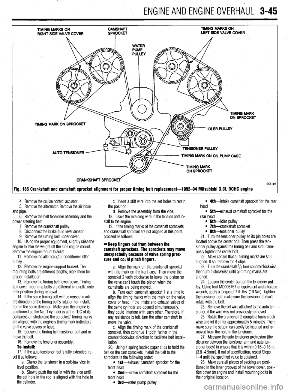
91251gb5 :ig. 185 Crankshaft and camshaft sprocket alignment for proper timing belt replacement-1992-94 Mitsubishi 3.OL DOHC engine
4. Remove the cruise control actuator.
5. Remove the alternator. Remove the air hose
and pipe.
6. Remove the belt tensioner assembly and the
power steering belt.
7. Remove the crankshaft pulley.
8. Disconnect the brake fluid level sensor.
9. Remove the timing belt upper cover.
10. Using the proper equipment, slightly raise the
engine to take the weight off the side engine mount.
Remove the engine mount bracket.
11. Remove the alternator/air conditioner idler
pulley.
12. Remove the engine support bracket. The
mounting bolts are different lengths; mark them for
proper installation.
13. Remove the timing belt lower cover. Timing
bolt cover mounting bolts are different in length, note
their position during removal.
14. If the same timing belt will be reused, mark
the direction of the timing belt’s rotation for installa-
tion in the same dlrection. Make sure the engine is
positioned so the No. 1 cylinder is at the TDC of its
compression stroke and the sprockets’timing marks
are aligned with the engine’s timing mark indicators
on the valve covers or head.
15. Loosen the timing belt tensioner bolt and re-
move the belt.
16. Remove the tensioner assembly.
To install:
17. If the auto tensioner rod is fully extended, re-
set it as follows:
a. Clamp the tensioner in a soft-jaw vice in
level position.
b. Slowly push the rod in with the vice until
the set hole in the rod is aligned with the hole in
the cylinder. c. Insert a stiff wire into the set holes to retain
the position.
d. Remove the assembly from the vice.
18. Leave the retaining wire in the tension and in-
stall to the engine.
19. If the timing marks of the camshaft sprockets
and crankshaft sprocket are not aligned at this point,
proceed as follows:
*Keep fingers out from between the
camshaft sprockets. The sprockets may move
unexpectedly because of valve spring pres-
sure and could pinch fingers.
a. Align the mark on the crankshaft sprocket
with the mark on the front case. Then move the
sprocket 2 teeth clockwise to lower the piston so
the valve can’t touch the piston when the
camshafts are being moved.
b. Turn each camshaft sprocket 1 at a time to
align the timing marks with the mark on the valve
cover or head. If the intake and exhaust valves of
the same cylinder are opened simultaneously,
they could interfere with each other. Therefore, if
any resistance is felt, turn the other camshaft to
move the valve.
c. Align the timing mark of the crankshaft
sprocket, then continue 1 tooth farther in the
counterclockwise direction to facilitate belt instal-
lation.
20. Using 4 spring loaded paper clips to hold the
belt on the cam sprockets, install the belt to the
sprockets in the following order:
l M-exhaust camshaft sprocket for the
front head
l 2nd-intake camshaft sprocket for the
front head
l trd-water pump pulley
l 5th-exhaust camshaft sprocket for tile
rear head
l Ah-intake camshaft sprocket for the rear
l Gth-idler pulley head l 7th-crankshaft sprocket l 8th-tensioner pulley
21. Turn the tensioner pulley so its pin holes are
located above the center bolt. Then press the ten-
sioner pulley against the timing belt and simultane-
ously tighten the center bolt.
22. Make certain that all timing marks are still
aligned. If so, remove the 4 clips.
23. Turn the crankshaft l/d turn counterclockwise,
then turn it clockwise until all timing marks are
aligned.
24. Loosen the center bolt on the tensioner pul-
ley. Using tool MD998767 or equivalent and a torque
wrench, apply a torque of 7 ft. Ibs. (10 Nm). Tighten
the tensioner bolt; make sure the tensioner doesn’t
rotate with the bolt.
25. Remove the set wire attached to the auto ten-
sioner, if the wire was not previously removed.
26. Rotate the crankshaft 2 complete turns clock-
wise and let it sit for approximately 5 minutes. Then,
make sure the set pin can easily be inserted and re-
moved from the hole in the tensioner.
27. Measure the auto tensioner protrusion (the
distance between the tensioner arm and auto ten-
sioner body) to ensure that it is within 0.15-0.18 in.
(3.8-4 5mm). If out of specification, repeat Steps
l-4 until the specified value is obtained.
28. Make sure all pieces of packing are posi-
tioned in the inner grooves of the lower cover, posi-
tion cover on engine and install mounting bolts in
their original location.
Page 107 of 408
3-46 ENGINEANDENGINEOVERHAUL
29. Install the engine support bracket and secure
using mounting bolts in their original location. Lubri-
cate the reaming area of the reamer bolt and tighten
slowly.
30. Install the idler pulley.
31. Install the engine mount bracket. Remove the
engine support fixture.
32. Make sure all pieces of packing are posi-
tioned in the inner grooves of the upper cover and in-
stall.
33. Connect the brake fluid level sensor.
34. Install the crankshaft pulley. Tighten the bolt
to 130-137ft. Ibs. (180-190 Nm).
35. install the belt tensioner assembly and the
power steering belt.
36 install the air hose and pipe.
37 Install the alternator.
38. Install the cruise control actuator.
39. Install the engine undercover.
40. Connect the negative battery cable.
199546 MODELS
# See Figure 186
1, Position the engine so the No. 1 cylinder is at
TDC of its compression stroke.
2. Disconnect the negative battery cable.
3. Remove the engine undercover.
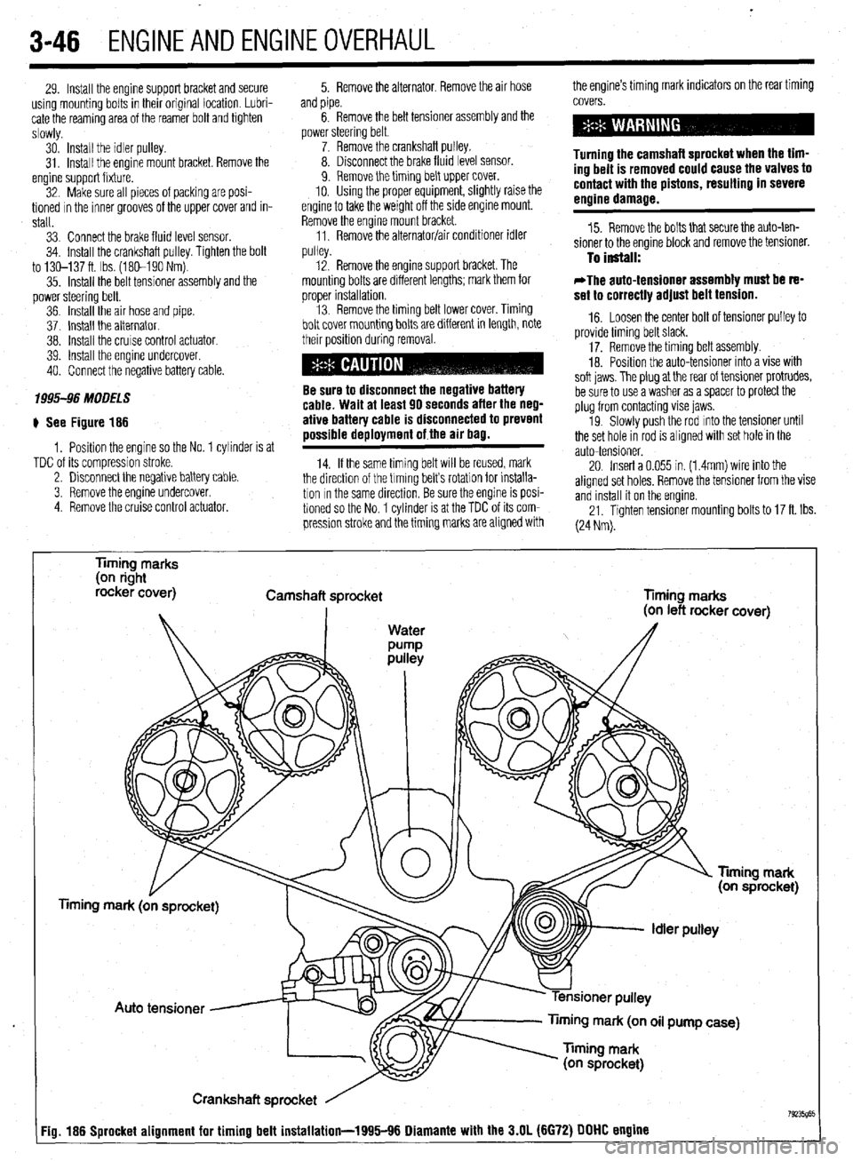
4 Remove the cruise control actuator. 5. Remove the alternator, Remove the air hose the engine’s timing mark indicators on the rear timing
and pipe.
6. Remove the belt tensioner assembly and the
power steering belt.
7. Remove the crankshaft pulley.
8. Disconnect the brake fluid level sensor.
9. Remove the timing belt upper cover.
10. Using the proper equipment, slightly raise the
engine to take the weight off the side engine mount.
Remove the engine mount bracket.
11, Remove the alternator/air conditioner idler
..,,ll^,. covers.
Turning the camshaft sprocket when the tim-
ing belt is removed could cause the valves to
contact with the pistons, resulting in severe
engine damage.
15. Remove the bolts that secure the auto-ten-
sioner to the engine block and remove the tensioner.
pu,ey. 12. Remove the engine support bracket. The To install:
mounting bolts are different lengths; mark them for
orooer installation. *The auto-tensioner assembly must be re-
set to correctlv adiust belt tension. , . 13. Remove the timing belt lower cover. Timing
bolt cover mounting bolts are different in length, note
their position during removal.
Be sure to disconnect the negative battery
cable. Wait at least 90 seconds after the neg-
ative battery cable is disconnected to prevent
possible deployment of the air bag.
14. If the same timing belt WIII be reused, mark
the direction of the trming belts rotation for installa-
tion In the same direction, Be sure the engine is posi-
tioned so the No. 1 cylinder is at the TDC of its com-
pression stroke and the timing marks are aligned with _ -
16. Loosen the center bolt of tensioner pulley to
provide timing belt slack.
17. Remove the timing belt assembly.
18. Posrtion the auto-tensioner into a vise with
soft iaws. The olua at the rear of tensioner protrudes,
be sure to usea v&her as a spacer to protect the
plug from contacting vise jaws.
19. Slowly push the rod mto the tensioner until
the set hole in rod is aligned with set hole in the
auto-tensioner.
20. Insert a 0.055 in. (1.4mm) wire into the
aligned set holes, Remove the tensioner from the vise
and install it on the engine.
21. Tighten tensioner mounting bolts to 17 ft. Ibs.
(24 Nm).
Timing marks
(on right
rocker cover)
Camshaft sprocket
Timing marks
mark (on oil pump case)
Crankshaft sprocket
Fig. 186 Sprocket alignment for timing belt installation-1995116 Diamante with the 3.N (6672) DDDD engine
Page 108 of 408
ENGINEANDENGINEOVERHAUL 3-47
DO NOT rotate or turn the camshafts when re-
moving the sprockets or severe engine dam-
age will result from internal component in-
terference.
22. Align the mark on the crankshaft sprocket
with the mark on the front case. Then, move the
crankshaft sprocket 1 tooth counterclockwise.
23. Align the timing marks of the camshafts with
the marks on the rear covers.
24. Using large paper clips to secure the timing
belt to the sprockets, install the timing belt in the fol-
lowing order. Be sure camshafts-to-cylinder heads
and crankshaft-to-front cover timing marks are
aligned. Install the timing belt around the pulleys in
the following order:
a. Exhaust camshaft sprocket (front bank).
b. Intake camshaft sprocket (front bank).
c. Water pump pulley.
d. Intake camshaft sprocket (rear bank).
e. Exhaust camshaft sprocket (rear bank).
f. Tensioner pulley.
g. Crankshaft pulley.
h. Idler pulley.
*Since the camshaft sprockets turn easily,
secure them with box wrenches when in-
stalling the timing belt.
25. Align all timing marks on the crankshaft and
raise the tensioner pulley against the belt to remove
slack, snug tensioner bolt.
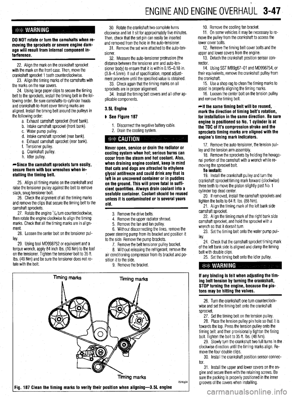
26. Check the alignment of all the timing marks
and remove the clips that secure the timing belt to the
camshaft sprockets.
27. Rotate the engine 1/4 turn counterclockwise,
then rotate the engine clockwise to align the timing
marks. Check that all the timing marks are in align-
ment.
28. Loosen the center bolt on the tensioner pul-
ley.
29. Using tool MD998752 or equivalent and a
torque wrench, apply 84 inch Ibs. (10 Nm) to the tool
on the tensioner. Tighten the tensioner bolt to 35 ft.
Ibs. (49 Nm) and be sure the tensioner does not ro-
tate with the bolt. 30. Rotate the crankshaft two complete turns
clockwise and let it sit for approximately five minutes.
Then, check that the set pin can easily be inserted
and removed from the hole in the auto-tensioner.
31. Remove the set wire attached to the auto-ten-
sioner
32. Measure the auto-tensioner protrusion (the
distance between the tensioner arm and auto-ten-
sioner body) to ensure that it is within 0.15-0.18 in.
(3.8-4.5mm). If out of specification, repeat adjust-
ment procedure until the specified value is obtained.
33. Check again that the timing marks on all
sprockets are in proper alignment.
34. Install the timing belt covers and all other ap-
plicable components.
3.51 Engine
p See Figure 187
1. Disconnect the negative battery cable.
2. Drain the cooling system.
Never open, service or drain the radiator or
cooling system when hot; serious burns can
occur from the steam and hot coolant. Also,
when draining engine coolant, keep in mind
that cats and dogs are attracted to ethylene
giycoi antifreeze and could drink any that is
left in an uncovered container or in puddles
on the ground. This will prove fatal in suffi-
cient quantities. Always drain coolant into a
sealable container. Coolant should be reused
unless it is contaminated or is several years
old.
3. Remove the drive belts.
4. Remove the upper radiator shroud.
5. Remove the fan and fan pulley.
6. Without disconnecting the lines, remove the
power steering pump from its bracket and position it
to the side Remove the pump brackets.
7. Remove the belt tensioner pulley bracket.
8. Without releasing the refrigerant, remove the
air conditioning compressor from its bracket and po-
sition it to the side.
9. Remove the bracket.
Timing marks
liming marks
Tinning marks
79245934 Fig. 187 Clean the timing marks to verify their position when aligning-3.51 engine
10. Remove the cooling fan bracket.
11, On some vehicles It may be necessary to re-
move the pulley from the crankshaft to access the
lower cover bolts.
12. Remove the timing belt cover bolts and the
upper and lower covers from the engme.
13. Detach the crankshaft position sensor con-
nector
14. Using SST MB9g67-01 and MD998754, or
their equivalents, remove the crankshaft pulley from
the crankshaft.
15. Use a shop rag to clean the timing marks to
assist in properly aligning the timing marks.
16. Loosen the center bolt on the tension pulley
and remove the timing belt.
@if the same timing belt will be reused,
mark the direction of timing belt’s rotation,
for installation in the same direction. Be sure
engine is positioned so No. 1 cylinder is at
the TDC of it’s compression stroke and the
sprockets timing marks are aligned with the
engine’s timing mark indicators.
17. Remove the auto-tensioner, the tension pul-
ley and the tension arm assembly.
18. Remove the sprockets by holding the hexago-
nal portion of the camshaft with a wrench while re-
moving the sprocket bolt.
To install: 19. Install the crankshaft pulley and turn the
crankshaft sprocket timing mark forward (clockwise)
three teeth to move the piston slightly past No. 1
cylinder top dead center.
20. If removed, install the camshaft sprockets and
tighten the bolts to 64 ft. Ibs. (88 Nm).
21, Align the timing mark of the left bank side
camshaft sprocket.
22. Align the timing mark of the right bank side
camshaft sprocket, and hold the sprocket with a
wrench so that it doesn’t turn.
23. Set the timing belt onto the water pump pul-
ley.
24. Check that the camshaft sprocket timing mark
of the left bank side is aligned and clamp the timing
belt with double clips.
25. Set the timing belt onto the idler pulley.
if any binding is felt when adjusting the tim-
ing belt tension by turning the crankshaft,
STOP turning the engine, because the pis-
tons may be hitting the valves.
26. Turn the crankshaft one turn counterclock-
wise and set the timing belt onto the crankshaft
sprocket.
27. Set the timing belt on the tension pulley.
28. Place the tension pulley pin hole so that it is
towards the top. Press the tension pulley onto the
timing belt, and then provisionally tighten the fixing
bolt. Tighten the bolt to 35 ft. Ibs. (48 Nm).
29. Slowly turn the crankshaft two full turns in the
clockwise direction until the timing marks align. Re-
move the four double clips.
30. Install the crankshaft position sensor connec-
tor.
31. Install the upper and lower covers on the en-
gine and secure them with the retaining screws. Be
sure the packing is properly positioned in the inner
grooves of the covers when installing.