1900 MITSUBISHI DIAMANTE steering
[x] Cancel search: steeringPage 233 of 408
6-30 CHASSIS ELECTRICAL
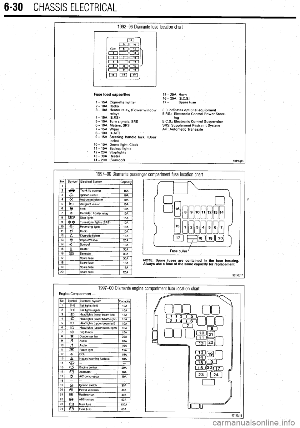
1992-96 Diamante fuse location chart
I
Fuse load caaacities 15 -2OA Horn
16 - 20A (E.C.S.)
1 - 15A Cigarette lighter 17 - spare fuse
2 - 10A Radio
3 - 10A Heater relay, (Power window ( ) indicates optlonal equipment
relay) E P.S.: Electronic Control Power Steer-
4 - 10A (E.P.S) ing
5 - 10A Turn signals, SRS E.C.S.: Electronic Control Suspension
6 - 10A Meters, SRS SRS~ Supplement Restratnt System
7 - 15A Wiper A/T: Automatic Transaxle
8-10A (4AIT)
9- 15A Steering handle lock, (Door
locks)
lo- 10A Dome light, Clock
11 - 10A Backup lights
12 -2OA StoplIghts
13 -3OA Heater
14 - 20A (Sunroof)
93156fllE
1997-00 Diamante passenger compartment fuse location chart No Symbol Electrical System
I capactty
I
Spare fuses are contained in the fuse housing
use a fuse of the same capacity for replacement.
199740 Diamante encline
compartment fuse location chart
Page 281 of 408
7-2 'DRIVETRAIN
Because of the way an internal combustron engine
breathes, it can produce torque, or twisting force,
only within a narrow speed range. Most modern,
overhead valve pushrod engines must turn at about
2500 rpm to produce their peak torque By 4500 rpm
they are producrng so lrttle torque that contrnued in-
creases in engine speed produce no power increases.
The torque peak on overhead camshaft engines IS
generally much higher, but much narrower.
The manual transaxle and clutch are employed to
vary the relationship between engine speed and the
speed of the wheels so that adequate engine power can
be produced under all crrcumstances. The clutch al-
lows engine torque to be applied to the transaxle input
shaft gradually, due to mechanical slippage. Conse-
quently, the vehicle may be started smoothly from a
full stop The transaxle changes the ratio between the
rotating speeds of the engine and the wheels by the
use of gears. The gear ratios allow full engine power to
be applied to the wheels during acceleration at low
speeds and at highway/passing speeds.
In a front wheel drive transaxle, power is usually
transmitted from the input shaft to a mainshaft or out-
put shaft located slightly beneath and to the side of
the input shaft. The gears of the mainshaft mesh with
gears on the input shaft, allowing power to be carried
from one to the other. All forward gears are in con-
stant mesh and are free from rotating with the shaft
unless the synchronizer and clutch IS engaged. Shaft-
ing from one gear to the next causes one of the gears
to be freed from rotating with the shaft and locks an-
other to it. Gears are locked and unlocked by internal
dog clutches which slide between the center of the
gear and the shaft. The forward gears employ syn-
chronizers; friction members which smoothly bring
gear and shaft to the same speed before the toothed
dog clutches are engaged.
SHIFT LINKAGE
1. Disconnect the shift linkage from the transaxle.
2. On the transaxle, put select lever in N and
move the shift lever in
4th gear. Depress the clutch,
if necessary, to shift.
3. Move the shift lever in the vehicle to the
4th gear position until it contacts the stop.
4. Turn the adjuster turnbuckle so the shift cable
eye aligns with the eye in the gear shift lever. When
installing the cable eye, make sure the flange side of
the plastic bushing at the shift cable end is on the
cotter pin side.
5 The cables should be adjusted so the clear-
ance between the shift lever and the 2 stoppers are
equal when the shift lever IS moved to 3rd and 4th
gear. Move the shift lever to each positron and check i
that the shifting is smooth
REMOVAL &INSTALLATION
1, Disconnect the negative battery cable 2. Remove any components necessary to access
the back-up light switch.
3. Unplug the back-up light switch connector.
4. Remove the switch from the case using the ap-
propriate size socket and drive tool.
To install: 5. Install the switch and tighten it to 22-25 ft. Ibs.
(30-35 Nm).
6. Attach the back-up light switch connector
7. Install any components removed to access the
back-up light switch
8. Connect the negative battery cable.
REMOVAL & INSTALLATION
Mirage
*If the vehicle is going to be roiled while the
halfshafts are out of the vehicle, obtain 2 outer
CV-joints or proper equivalent tools and install
to the hubs. If the vehicle is rolled without the
proper torque applied to the front wheel bear-
ings, the bearings will no longer be usable.
*The suspension components should not be
tightened until the vehicles weight is resting
on the ground.
1. Remove the battery and battery tray.
2. Remove the air cleaner assembly and vacuum
hoses.
3. Note the locations and disconnect the shifter
cables.
4. If equipped with 1.61 engine, remove the ten-
sion rod.
5. Detach the backup lamp switch connector,
speedometer cable connection and remove the starter
motor.
6. Raise the vehicle and support safely.
7. Remove the front wheels and the inner wheel
panels.
8. Remove the undercover and splash pan.
9. Drain the transaxle oil into a suitable con-
tainer
10. Support the engine and remove the cross-
member.
11. Remove the upper transaxle mounting bolt
and bracket.
12 Disconnect the stabilizer bar, tie rod ends and
the lower ball joint connections.
13 Remove the clutch release cylinder and clutch
oil line bracket. Do not disconnect the fluid lines and
secure the slave cylinder with wire.
14 Disconnect the clutch cable, if equipped with
cable controlled clutch system.
15. Remove the halfshafts by inserting a prybar
between the transaxle case and the driveshaft and
prying the shaft from the transaxle. Do not pull on the
driveshaft Doing so damages the inboard joint. Do
not insert the prybar so far the oil seal in the case is
damaged.
*It is not necessary to disconnect the half-
shafts from the steering knuckle. Remove the
shaft with the hub and knuckle as an assem-
bly. Tie the shafts aside. Note the circle clip
on the end of the inboard shafts should not
be reused.
16. Remove the bellhousing lower cover.
17 Remove the transaxle to engine bolts and
lower the transaxle from the vehrcle.
To install:
*When installing the transaxle, be sure to
align the splines of the transaxle with the
clutch disc.
18 Install the transaxle to the engine and install
the mounting bolts. Tighten the bolts to 31-40 ft. Ibs.
(43-55 Nm) on 1990-92 models and 35 ft. Ibs. (48
Nm) on 1993-00 models.
19 Install the bellhousing cover.
*When installing the halfshafts, use new
circlips on the axle ends. Care must be taken
to ensure that the oil seal lip of the transaxle
is not damaged by the serrated part of the
driveshaft.
20. Install and fully seat the halfshafts into the
transaxle.
21. Install the slave cylinder.
22. Connect the ball joints, tie rod ends and the
stabilizer bar connections.
23. Install the upper transaxle mounting bracket
and bolt.
24. Install the crossmember.
25. Install the undercover.
26. Install the upper transaxle-to-engine mount-
ing bolts, Tighten the bolts to 31-40 ft. Ibs. (43-55
Nm) on 199C-92 models and 35 ff. Ibs. (48 Nm) on
1993-00 models.
27. Install the starter motor.
28 Connect the backup light switch connector
and speedometer cable.
29 Connect and adjust the shifter cables.
30 Install the air cleaner assembly.
31. Install the front wheels.
32 Make sure the vehicle is level when refilling
the transaxle Use Hypoid gear oil or equivalent, GL-
4 or higher.
33. Connect the negative battery cable and check
the transaxle for proper operation. Make sure the re-
verse lights operate when in reverse.
Galant
1999-93 MODELS
rlf the vehicle is going to be rolled on its
wheels while the halfshafts are out of the ve-
hicle, obtain two outer CV-joints or proper
equivalent tools and install to the hubs. If the
vehicle is rolled without the proper torque
applied to the front wheel bearings, the bear-
ings will no longer be usable.
1. Remove the battery and the air intake hoses.
2. If equipped with Active-ECS, unplug the
compressor wiring.
3. Remove the auto-cruise actuator and under-
hood bracket, located on the passenger side inner
fender well.
4. Drain the transaxle and transfer case fluid, if
equipped, into a suitable waste container.
5. Remove the retainer bolt and pull the
speedometer cable from the transaxle assembly.
6. Remove the cotter pin securing the select and
shift cables and remove the cable ends from the
transaxle.
Page 282 of 408
DRIVETRAIN 7-3
7. Remove the connection for the clutch release
38. Install the battery.
bolt to 54 ft. Ibs. (73 Nm). Install the front engine roll
cylinder and without disconnecting the hydraulic line,
39. If equipped with Active-ECS, connect the air
stopper through-bolt and hand-tighten. Once the full
and secure it aside.
compressor.
weight of the engine is on the mounts, tighten the
8. Disconnect the backup light switch harness
40. Make sure the vehicle is level when refilling
bolt to 42 ft. Ibs. (57 Nm).
and position aside.
the transaxle. Use Hypoid gear oil or equivalent, GL-
30.
Install the triangular stay bracket and tighten
9. Detach the starter electrical connections, if
4 or higher.
the mounting bolts to 65 ft. Ibs. (88 Nm).
necessary, remove the starter motor and position
41. Check the transaxle and transfer case for
31. Connect the clutch release cylinder.
aside.
proper operation. Make sure the reverse lights come
32. Install the halfshafts, using new circlips on
10. Remove the transaxle mount bracket.
on when in reverse.
the axle ends.
11. Remove the upper transaxle mounting bolts.
12.
Raise the vehicle and support safely on jack-
1!I94-Ol? MODELS
stands.
13. Remove the undercover and the front wheels. 1. Disconnect the negative battery cable and When histalling the axleshaft, keep the in-
14.
Remove the cotter pin and disconnect the tie wait at least 90 seconds before performing any work. board joint straight in relation to the axle, so
rod end from the steering knuckle. 2. Remove the air cleaner and intake hoses. not to damage the oil seal lip of the
15. Remove the self-locking nut from the half- 3. Drain the transaxle into a suitable waste con- transaxle, with the serrated part of the half-
ShaftS. tainer. shaft.
16.
Disconnect the lower arm ball joint from the 4. Remove the cotter pins and clips securing the
steering knuckle. select and shift cables and remove the cable ends 33. Connect the tie rod and ball joints to the steer-
17. Remove the halfshafts from the transaxle. from the transaxle. ing knuckle. Tighten the ball joint self-locking nuts to
18. On AWD models, disconnect the front ex- 5. If equipped with Active-ECS, disconnect the 48 ft. Ibs. (65 Nm). Tighten the tie rod end nut to 21 ft.
haust pipe. air compressor. Ibs. (28 Nm) and secure with a new cotter pin.
19.
On AWD ‘models, remove the transfer case by 6. Disconnect the backup light switch harness 34.
Connect the damper fork to the lower control
removing the attaching bolts, moving the transfer and position aside. arm and tighten the through-bolt to 65 ft. Ibs. (88 Nm).
case to the left and lowering the front side. Remove it 7. Disconnect the speedometer electrical con- 35.
Connect the stabilizer link to the damper fork,
from the rear driveshaft. Be careful of the oil seal. Do nectar, from the transaxle assembly. and tighten the self-locking nut to 29 ft. Ibs. (39 Nm).
not allow the driveshaft to hang; once the front is re- 8. Remove the starter motor and position aside. 36. Install the underpan.
moved from the transfer, tie it up. Cover the transfer 9. Using special tool M2203827 or equivalent, 37. Install wheels and lower vehicle.
case openings to keep out dirt. support the engine assembly. 38. Install the transaxle mount bracket to the
20.
Remove the cover from the transaxle bell- 10. Remove the rear roll stopper mounting transaxle, and tighten the mounting nuts to 32 ft. Ibs.
housing. bracket. (43 Nm).
21. On AWD models, remove the crossmember 11. Remove the transaxle mount bracket. 39. install the rear roll stopper mounting bracket.
and the triangular gusset. 12. Remove the upper transaxle mounting bolts. 40.
Remove the engine support. Tighten the
22. Remove the transaxle lower coupling bolt. It 13. Raise and safely support the vehicle. transaxle mount through-bolt to 51 ft. Ibs. (69 Nm)
is just above the halfshaft opening on FWD or trans- 14. Remove the front wheel assemblies. and tighten the front engine roll stopper through-bolt.
fer case opening on AWD. 15. Remove the right hand undercover. 41. Install the upper transaxle mounting bolts
23.
Support the weight of the engine from above 16. Remove the cotter pin and disconnect the tie and tighten to 35 ft. Ibs. (48 Nm).
(chain hoist). Support the transaxle using a transmis- rod end, from the steering knuckle. 42. Install the starter motor.
sion jack and remove the remaining lower mounting 17. Disconnect the stabilizer bar link, from the 43. Attach the backup light switch and the
bolts. damper fork. speedometer connector.
24. On turbocharged vehicle, be careful not to 18. Disconnect the damper fork, from the lateral 44.
Connect the select and shift cables and install
damage the lower radiator hose with the transaxle lower control arm. new cotter pins.
housing during removal. Wrap tape on both the lower 19. Disconnect the later lower arm, and the com- 45.
Install the air cleaner and the air intake hose.
hose and the transaxle housing to prevent damage. pression arm, lower ball joints, from the steering 46. Connect the negative battery cable.
Move the transaxle assembly to the right and care- knuckle. 47. Make sure the vehicle is level, and refill the
fully lower it from the vehicle. 20. Pry the halfshafts from the transaxle, and se- transaxle.
To install: cure aside. 48.
Check the transaxle for proper operation. Make
25.
Install the transaxle to the engine and install 21. Remove the connection for the clutch release sure the reverse lights come on when in reverse.
the mounting bolts, Tighten the bolts to 35 ft. Ibs. (48 cylinder and without disconnecting the hydraulic line,
Nm). Install the transaxle lower coupling bolt. secure aside.
26.
Install the underpan, crossmember and the 22. Remove the cover from the transaxle bell-
triangular gusset. housing.
27.
Install the transfer case on AWD models and 23. Remove the engine front roll stopper REMOVAL&INSTALLATION
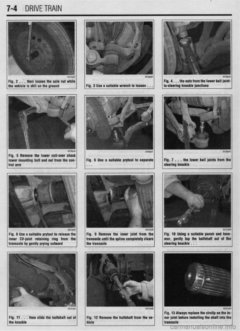
connect the exhaust pipe. through-bolt.
28.
Install the halfshafts, using new circlips on 24. Remove the crossmember and the triangular ) See Figures 1 thru 13
the axle ends. Try to keep the inboard joint straight in right hand stay.
relation to the axle. Be careful not to damage the oil 25. Support the transaxle, using a transmission
seal lip of the transaxle with the serrated part of the jack, and remove the transaxle lower coupling bolt.
halfshaft.
29. Connect the tie rod and ball joint to the steer- *The coupling bolt threads from the englne
side, into the transaxle, and is located just
ing knuckle.
30. Install the transaxle mount bracket. above the halfshaft opening.
31. Install wheels and lower vehicle. Retorque 26. Slide the transaxle rearward and carefully
axle shaft nuts to 145-188 ft. Ibs. (200-260 Nm). lower it from the vehicle.
32. Install the starter motor. To install:
33. Connect the backup light switch and the 27. Install the transaxle to the engine. Install the
speedometer cable. mounting bolts and tighten to 35 ft. Ibs. (48 Nm). In-
34. Install the clutch release cylinder. stall the transaxle lower coupling bolt and tighten to
35.
Connect the select and shift cables and install 22-25 ft. Ibs. (30-34 Nm).
new cotter pins. 28. Install the cover to the transaxle bellhousing
36. Install the air intake hose. and tighten the mounting bolts to 7 ft. Ibs. (9 Nm).
37. Install the auto-cruise actuator and bracket. 29. Install the crossmember and tighten the front
mounting bolts to 65 ft. Ibs. (88 Nm) and the rear
Page 283 of 408
.
7-4 DRIVETRAIN
Fig. 2 . . . then loosen the axle nut while
the vehicle is still on the ground
Fig. 5 Remove the lower coil-over shock
lower mounting bolt and nut from the con-
trol arm
I
93157po7 Fig. 8 Use a suitable prytool to release the
inner CV-joint retaining ring from the
transaxle by gently prying outward
Fig, 11 , , .
then slide the halfshaft out of
the knuckle Fig. 9 Remove the inner joint from the
transaxle until the spline completely clears
the transaxle Fig. 7 . . , the lot Fig. 7 . . / the lower ball joints from the
steering knuckle steering knuckle 93157pcn Fig. 10 Uslng a suitable punch and ham-
mer, gently tap the halfshaft out of the
steering knuckle . . .
I I Fig, 13 Always replace the clrcllp on the in-
Fig. 12 Remove the halfshaft from the ve- ner joint before installing the shaft Into the
hlcle transaxle
Page 284 of 408
DRIVETRAIN 7-5
1, While the vehicle is still on the ground, re- IO. Insert the halfshaft into the tram&e. Be sure cle is being serviced could make a difference in joint
move the cotter pin, and loosen the axle nut. it is fully seated. type. Be sure to properly identify the joint before at-
2. Raise the vehicle and support it safely. 1 I. Pull the strut assembly out and install the tempting joint or boot replacement. Look for identifi-
3. If equipped with ABS, remove the front wheel other end to the hub. cation numbers at the large end of the boots and/or
speed sensor. 12. Install the center bearing bracket bolts and on the end of the metal retainer bands.
4. If equipped with Active Electronic Control tighten to 33 ft. Ibs. (45 Nm). The 3 types of joints used are the Birfield Joint,
Suspension (Active-ECS), perform the following: 13. Install the washer on the axle shaft so the (B.J.), the Tripod Joint (T.J.) and the Double Offset
a. Loosen the nut that secures the air line to chamfered edge faces outward. Install the axle nut, Joint (D.O.J.).
the to the top of the strut and discard the O-ring.
b. Remove the bolts that secure the actuator but do not tighten it fully at this time.
14. Connect the ball joint to the steering knuckle. *Do not disassemble a Birfield joint. Ser-
to.the top of the strut and remove the compo-
Torque the new retaining nut to 43-52 ft. Ibs. (68-72 vice with a new joint or clean and repack us-
nent. Disconnect the wiring harness.
Nm) and secure with a new cotter pin. ing a new boot kit.
5. Disconnect the lower ball joint and the tie rod
15. Connect the tie rod end to the steering
The distance between the large and small boot
end from the steering knuckle.
knuckle. Torque the retaining nut to 21 ft. Ibs. (29
bands is important and should be checked prior to
6. Remove the axle nut and the washer.
Nm) and secure with a new cotter pin.
and after boot service. This is so the boot will not be
7. If removing the left side axle with an inner 16. If equipped with ABS, install the front wheel
installed either too loose or too tight, which could
shaft, remove the center support bearing bracket speed sensor.
cause early wear and cracking, allowing the grease to
bolts and washers. Then, remove the halfshaft by set-
17. If equipped with Active-KS, perform the fol- get out and water and dirt in, leading to early joint
ting up a puller on the outside wheel hub and push-
lowing:
failure.
ing the halfshaft from the front hub. Tap the shaft a. Install the air line with a new O-ring.
union at the joint case with a plastic hammer to re- b. Install the actuator to the top of the strut. *The drfveshaft joints use special grease;
move the halfshaft and inner shaft from the transaxle. Connect the wiring harness. do not add any grease other than that sup-
8. If removing right side axle shafts without an 18. Install the wheel and lower the vehicle to the plied with the kit.
inner shaft, remove the halfshaft by setting up a floor.
puller on the outside wheel hub and pushing the half- 19. Tighten the axle nut to 145-188 ft. Ibs.
Double Offset Joint
shaft from the front hub. After pressing the outer (200-260 Nm) and secure with a new cotter pin.
shaft, insert a prybar between the transaxle case and The Double Offset Joint (D.O.J.) is bigger than
the halfshaft and pry the shaft from the transaxle.
CV-JOINTS OVERHAUL other joints and, in these applications, is normally
*Do not pull on the shaft; doing so damages used as an inboard joint.
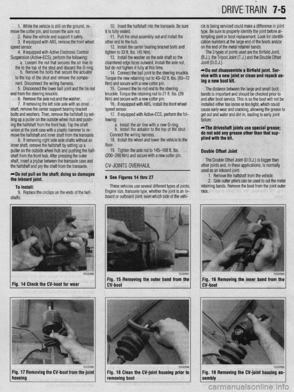
the inboard joint. b See Figures 14 thru 27 1. Remove the halfshaft from the vehicle.
2. Side cutter pliers can be used to cut the metal
To install: These vehicles use several different types of joints. retaining bands. Remove the boot from the joint outer
9. Replace the circlips on the ends of the half- Engine size, transaxle type, whether the joint is an in- race.
shafts. board or outboard joint, even which side of the vehi-
TCCS7030 TCCS7031
I I TCCS7032 Fig. 15 Removing the outer band from the
Fig. 16 Removing the inner band from the
Fig. 14 Check the CV-boot for wear
W-boot
lho~sing IFi7~ / Fig 17 Removing the CV-boot from the joint 1 1 CV-boot
TCCS7035 Fig 18 Clean the CV-joint housing prior to
removing boot Tccs7W 1 1 sembiy Fig 19 Removing the CV-joint housing as-
Page 289 of 408
7-10 DRIVETRAIN
The automatic transaxle allows engine torque and
power to be transmitted to the front wheels within a
narrow range of engine operating speeds. It will allow
the engine to turn fast enough to produce plenty of
power and torque at very low speeds, while keeping it
at a sensible rpm at high vehicle speeds (and it does
this job without driver assistance). The transaxle uses
a light fluid as the medium for the transmission of
power. This fluid also works in ths operation of vari-
ous hydraulic control circuits and as a lubricant. Be-
cause the transaxle fluid performs all of these func-
tions, trouble within the unit can easily travel from one
part to another For this reason, and because of the
complexity and unusual operating principles of the
transaxle, a very sound understanding of the basic
principles of operation will simplify troubleshooting
REMOVAL &INSTALLATION
Pan removal, fluid and filter
in Section 1 of this manual changes are covered
REMOVAL &INSTALLATION
1990-97 Mirage and 1990-93 Galant
# See Figure 44
1. Disconnect the negative battery cable.
2. Disconnect the selector cable from the lever
3. Remove the two retaining screws and lift off
the switch.
To install: 4. Mount and position new switch. Do not tighten
the bolts until the switch is adjusted.
5. Connect selector cable and adjust switch.
6. After installation and adjustment make sure the
engine only starts in the
P and N selections. Also check
that the reverse lights operate only in the R selectlon.
1994-00 Galant and 1998-00 Mirage
e See Figure 44
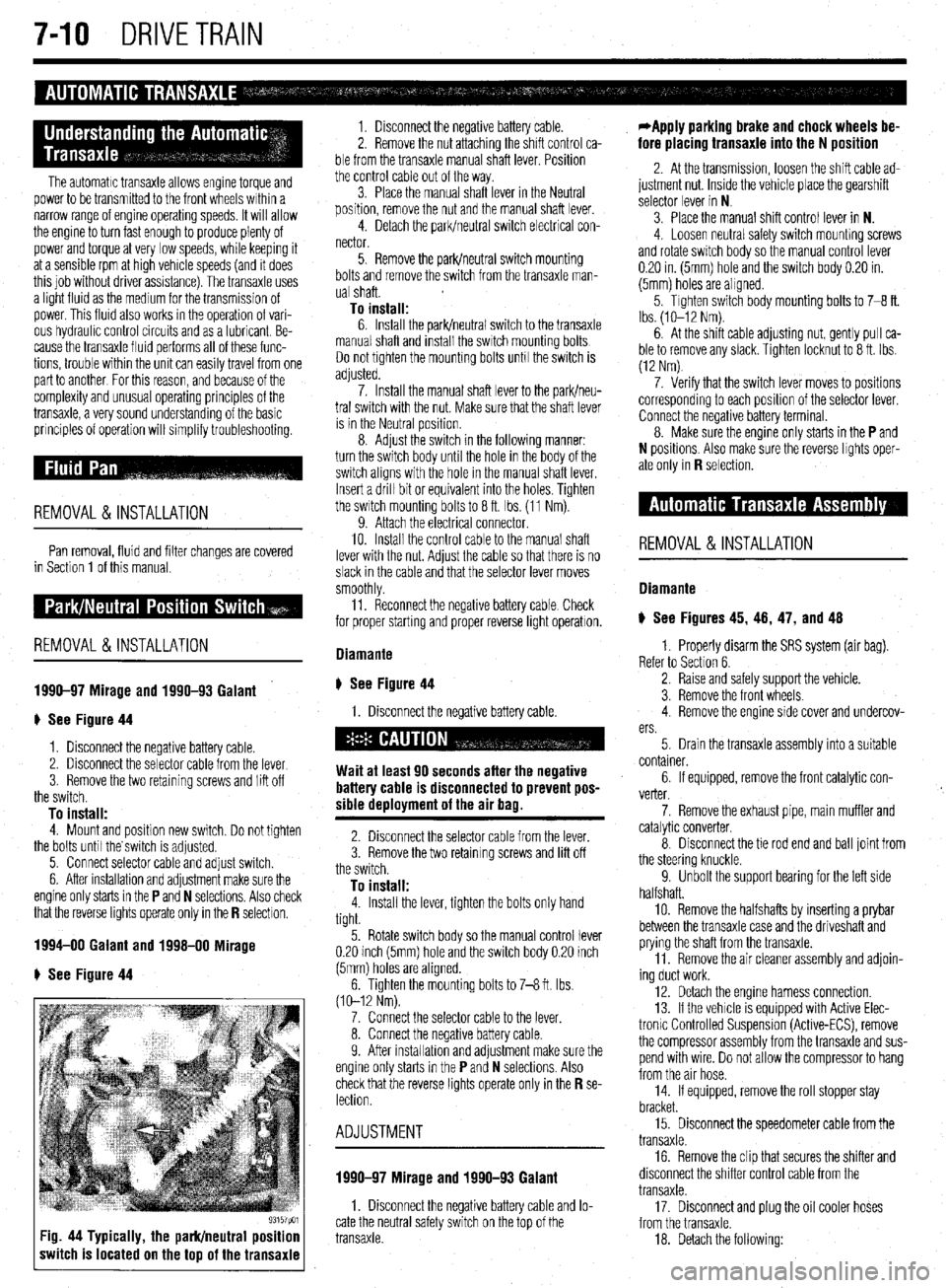
93157pm Fig. 44 Typically, the park/neutral position
switch is located on the top of the transaxle
1. Disconnect the negative battery cable.
2. Remove the nut attaching the shift control ca-
ble from the transaxle manual shaft lever. Position
the control cable out of the way.
3. Place the manual shaft lever in the Neutral
position, remove the nut and the manual shaft lever.
4. Detach the park/neutral switch electrical con-
nector.
5. Remove the park/neutral switch mounting
bolts and remove the switch from the transaxle man-
ual shaft.
To install: 6. Install the park/neutral switch to the transaxle
manual shaft and install the switch mounting bolts
Do not tighten the mounting bolts unh the switch is
adjusted.
7. Install the manual shaft lever to the park/neu-
tral switch with the nut. Make sure that the shaft lever
is in the Neutral position.
8. Adjust the switch in the following manner:
turn the switch body until the hole in the body of the
switch aligns with the hole in the manual shaft lever.
Insert a drill bit or equivalent into the holes. Tighten
the switch mounting bolts to 8 ft. Ibs. (11 Nm).
9. Attach the electrical connector.
10. Install the control cable to the manual shaft
lever with the nut. Adjust the cable so that there is no
slack in the cable and that the selector lever moves
smoothly
11. Reconnect the negative battery cable Check
for proper starting and proper reverse light operatron.
Diamante
ti See Figure 44
1. Disconnect the negative battery cable.
Wait at least 90 seconds after the negative
battery cable is disconnected to prevent pos-
sible deployment of the air bag.
2. Disconnect the selector cable from the lever.
3. Remove the two retaining screws and lift off
the switch.
To install: 4. Install the lever, tighten the bolts only hand
tight.
5. Rotate switch body so the manual control lever
0.20 inch (5mm) hole and the switch body 0.20 inch
(5mm) holes are aligned.
6. Tighten the mounting bolts to 7-8 ft. Ibs.
(10-12 Nm).
7. Connect the selector cable to the lever.
8. Connect the negative battery cable.
9. After installahon and adjustment make sure the
engine only starts in the
P and N selections. Also
check that the reverse lights operate only in the R se- lection.
ADJUSTMENT
1990-97 Mirage and 1990-93 Galant
1. Disconnect the negative battery cable and lo-
cate the neutral safety switch on the top of the
transaxle.
*Apply parking brake and chock wheels be-
fore placing transaxle into the N position
2. At the transmission, loosen the shift cable ad-
justment nut. Inside the vehicle place the gearshift
selector lever in N
3. Place the manual shift control lever in N.
4. Loosen neutral safety switch mounhng screws
and rotate switch body so the manual control lever
0.20 in. (5mm) hole and the switch body 0.20 in.
(5mm) holes are aligned.
5. Tighten switch body mounting bolts to 7-8 ft.
Ibs. (lo-12 Nm).
6. At the shift cable adjusting nut, gently pull ca-
ble to remove any slack. Tighten locknut to 8 ft. Ibs.
(12 Nm)
7. Verify that the switch lever moves to positions
corresponding to each position of the selector lever.
Connect the negative battery terminal.
8. Make sure the engine only starts in the
P and
N positions. Also make sure the reverse lights oper-
ate only in
R selection.
REMOVAL&INSTALLATION
Diamante
) See Figures 45, 46, 47, and 48
1. Properly disarm the SRS system (air bag).
Refer to Section 6.
2. Raise and safely support the vehicle.
3. Remove the front wheels.
4. Remove the engine side cover and undercov-
ers.
5. Drain the transaxle assembly into a suitable
container.
6. If equipped, remove the front catalytic con-
verter.
7. Remove the exhaust pipe, main muffler and
catalytic converter.
8. Disconnect the tie rod end and ball joint from
the steering knuckle.
9. Unbolt the support bearing for the left side
halfshaft.
10. Remove the halfshafts by inserting a prybar
between the transaxle case and the driveshaft and
prying the shaft from the transaxle.
11. Remove the air cleaner assembly and adjoin-
ing duct work.
12. Detach the engine harness connection.
13. If the vehicle is equipped with Active Elec-
tronlc Controlled Suspension (Active-ECS), remove
the compressor assembly from the transaxle and sus-
pend with wire. Do not allow the compressor to hang
from the air hose.
14. If equipped, remove the roll stopper stay
bracket.
15. Disconnect the speedometer cable from the
transaxle.
16. Remove the clip that secures the shifter and
disconnect the shifter control cable from the
transaxle.
17. Disconnect and plug the oil cooler hoses
from the transaxle.
18. Detach the following:
Page 290 of 408
DRIVETRAIN 7-11
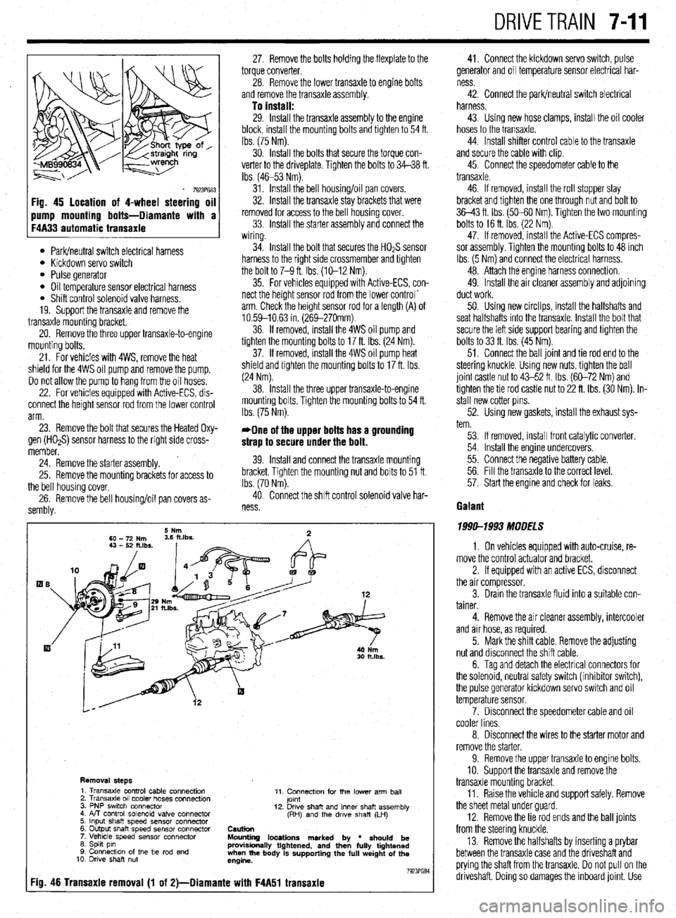
Fig. 45 location of 4-wheel steering oil
l Park/neutral switch electrical harness l Kickdown servo switch l Pulse generator l Oil temperature sensor electrical harness l Shift control solenoid valve harness.
19. Support the transaxle and remove the
transaxle mounting bracket.
20. Remove the three upper transaxle-to-engine
mounting bolts.
21. For vehicles with 4WS, remove the heat
shield for the 4WS oil pump and remove the pump.
Do not allow the pump to hang from the oil hoses.
22. For vehicles equipped with Active-ECS, dis-
connect the height sensor rod from the lower control
arm.
23. Remove the bolt that secures the Heated Oxy-
gen (HOaS) sensor harness to the right side cross-
member.
’ 24. Remove the starter assembly.
25. Remove the mounting brackets for access to
the bell housing cover,
26. Remove the bell housing/oil pan covers as-
sembly. 27. Remove the bolts holding the flexplate to the
torque converter.
28. Remove the lower transaxle to engine bolts
and remove the transaxle assembly.
To install: 29. Install the transaxle assembly to the engine
block, install the mounting bolts and tighten to 54 ft.
tbs. (75 Nm).
30. Install the bolts that secure the torque con-
verter to the driveplate. Tighten the bolts to 34-38 ft.
Ibs (4653 Nm).
31. Install the bell housing/oil pan covers.
32. Install the transaxle stay brackets that were
removed for access to the bell housing cover.
33. Install the starter assembly and connect the
wiring.
34. Install the bolt that secures the HO& sensor
harness to the right side crossmember and tighten
the bolt to 7-9 ft. Ibs. (X-12 Nm).
35. For vehicles equipped with Active-ECS, con-
nect the height sensor rod from the lower control’
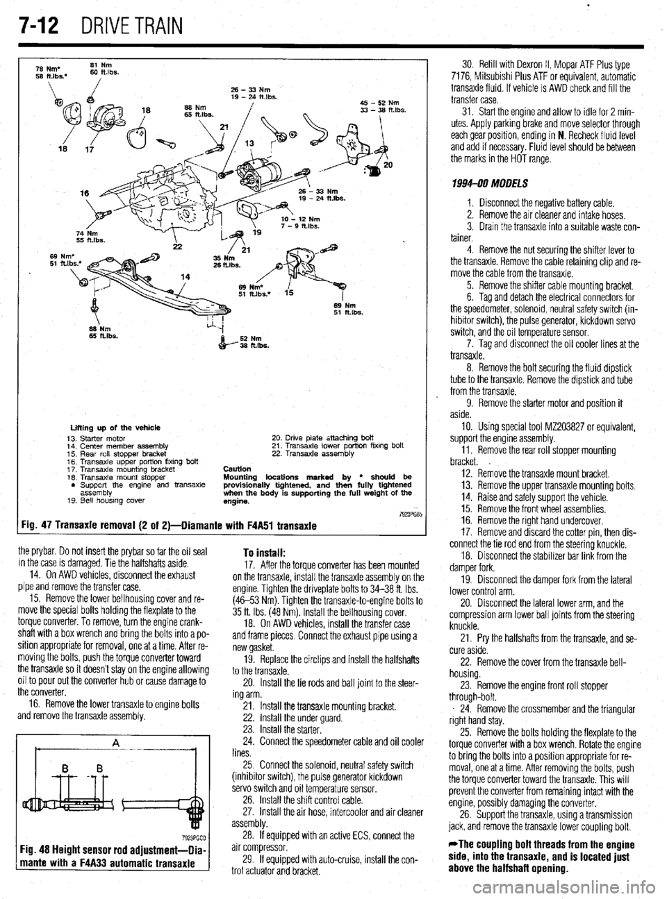
arm. Check the height sensor rod for a length (A) of
10.59-10.63 in. (269-270mm)
36. If removed, install the 4WS oil pump and
tighten the mounting bolts to 17 ft. Ibs. (24 Nm).
37. If removed, install the 4WS oil pump heat
shield and tighten the mounting bolts to 17 ft. Ibs.
(24 Nm).
38. Install the three upper transaxle-to-engine
mounting bolts. Tighten the mounting bolts to 54 ft.
Ibs. (75 Nm).
*One of the upper bolts has a grounding
strap to secure under the bolt.
39. Install and connect the transaxle mounting
bracket. Tighten the mounting nut and bolts to 51 ft.
Ibs. (70 Nm).
40. Connect the shift control solenoid valve har-
ness
Removal steps 1. Transaxle control cable connection
2. Transaxle 011 cooler hoses connection
3. PNP swrtch connector
4. FvT control solenoid valve connector
5. Input shaft speed sensor connector
6. Output shaft speed sensor connector
7. Vehicle speed sensor connector
6. Spht pin
9. Connection of the tie rod end
10. Drwe shaft nut 11. Connectton for the lower arm ball
jomt
12. Drwe shaft and inner shaft assembly
(RH) and the drwe shaft (LH)
Caution
Mounting locations marked by
l should be
provisionally tightened, and then fully tightened
when the body is supporting the full weight of the
engine.
7923PG84
:io. 46 Transaxie removal (1 of 2)-Diamante with F4A51 transaxie
41. Connect the kickdown servo switch, pulse
generator and oil temperature sensor electrical har-
ness
42. Connect the park/neutral switch electrical
harness.
43. Using new hose clamps, install the oil cooler
hoses to the transaxle.
44. Install shifter control cable to the transaxle
and secure the cable with clip.
45. Connect the speedometer cable to the
transaxle.
46. If removed, install the roll stopper stay
bracket and tighten the one through nut and bolt to
36-43 ft. Ibs. (50-60 Nm). Tighten the two mounting
bolts to 16 ft. Ibs. (22 Nm).
47. If removed, install the Active-ECS compres-
sor assembly. Tighten the mounting bolts to 48 inch
Ibs. (5 Nm) and connect the electrical harness.
48. Attach the engine harness connection.
49. Install the air cleaner assembly and adjoining
duct work.
50. Using new circlips, install the halfshafts and
seat halfshafts into the transaxle. Install the bolt that
secure the left side support bearing and tighten the
bolts to 33 ft. Ibs. (45 Nm).
51. Connect the ball joint and tie rod end to the
steering knuckle. Using new nuts, tighten the ball
joint castle nut to 43-52 ft. Ibs. (60-72 Nm) and
tighten the tie rod castle nut to 22 ft. ibs. (30 Nm). in-
stall new cotter pins.
52. Using new gaskets, install the exhaust sys-
tem.
53. If removed, install front catalytic converter.
54. Install the engine undercovers.
55. Connect the negative battery cable.
56. Fill the transaxle to the correct level.
57. Start the engine and check for leaks.
Gaiant
1999-1993 MODELS
1. On vehicles equipped with auto-cruise, re-
move the control actuator and bracket.
2. If equipped with an active ECS, disconnect
the air compressor.
3. Drain the transaxle fluid into a suitable con-
tainer.
4. Remove the air cleaner assembly, intercooler
and air hose, as required.
5. Mark the shift cable. Remove the adjusting
nut and disconnect the shift cable.
6. Tag and detach the electrical connectors for
the solenoid, neutral safety switch (inhibitor switch),
the pulse generator kickdown servo switch and oil
temperature sensor.
7. Disconnect the speedometer cable and oil
cooler lines.
8. Disconnect the wires to the starter motor and
remove the starter.
9. Remove the upper transaxle to engine bolts.
10. Support the transaxle and remove the
transaxle mounting bracket.
11. Raise the vehicle and support safely. Remove
the sheet metal under guard
12. Remove the tie rod ends and the bail joints
from the steering knuckle.
13. Remove the halfshafts by inserting a prybar
between the transaxle case and the driveshaft and
prying the shaft from the transaxle. Do not pull on the
driveshaft. Doing so damages the inboard joint. Use
Page 291 of 408
.
7-12 DRIVETRAIN
26-33Nm
19 - 24 itlbs.
45 - 52 Nm
69 Nm
51 ftlbs.
66 Nm
65 ftlbs.
52 Nm
36 fl.lbs.
:ig.
the prybar. Do not insert the prybar so far the oil seal
in the case is damaged. Tie the halfshafts aside.
14. On AWD vehicles, disconnect the exhaust
pipe and remove the transfer case.
15. Remove the lower bellhousing cover and re-
move the special bolts holding the flexplate to the
torque converter. To remove, turn the engine crank-
shaft with a box wrench and bring the bolts into a po-
sition appropriate for removal, one at a time. After re-
moving the bolts, push the torque converter toward
the transaxle so it doesn’t stay on the engine allowing
oil to pour out the converter hub or cause damage to
the converter,
16. Remove the lower transaxle to engine bolts
and remove the transaxle assembly. To install: 17. After the torque converter has been mounted
on the transaxle, install the transaxle assembly on the
engine. Tighten the driveplate bolts to 34-38 ft. Ibs.
(4653 Nm). Tighten the transaxle-to-engine bolts to
35 ft. Ibs. (48 Nm). Install the bellhousing cover.
18. On AWD vehicles, install the transfer case
and frame pieces. Connect the exhaust pipe using a
new gasket.
19. Replace the circlips and install the halfshafts
to the transaxle.
20. Install the tie rods and ball joint to the steer-
ing arm.
21. Install the transaxle mounting bracket.
22. install the under guard.
23. Install the starter.
24. Connect the speedometer cable and oil cooler
lines.
25 Connect the solenoid, neutral safety switch
(inhibitor switch), the pulse generator kickdown
servo switch and oil temperature sensor.
26. Install the shift control cable.
27. Install the air hose, intercooler and air cleaner
assembly.
If equipped with an active ECS, connect the
mante with a F4A33 automatic transaxle
30 Refill with Dexron II, Mopar ATF Plus type
7176, Mitsubishi Plus ATF or equivalent, automatic
transaxle fluid. If vehicle is AWD check and fill the
transfer case.
31. Start the engine and allow to idle for 2 min-
utes. Apply parkrng brake and move selector through
each gear posrtion, ending in N. Recheck fluid level
and add if necessary. Fluid level should be between
the marks in the HOT range.
1994-90 MODELS
1. Disconnect the negative battery cable.
2. Remove the air cleaner and intake hoses.
3. Drain the transaxle into a suitable waste con-
tainer.
4. Remove the nut securing the shifter lever to
the transaxle. Remove the cable retaining clip and re-
move the cable from the transaxle.
5. Remove the shifter cable mounting bracket,
6. Tag and detach the electrical connectors for
the speedometer, solenoid, neutral safety switch (in-
hibitor switch), the pulse generator, kickdown servo
switch, and the oil temperature sensor.
7. Tag and disconnect the oil cooler lines at the
transaxle.
8. Remove the bolt securing the fluid dipstick
tube to the transaxle. Remove the dipstrck and tube
from the transaxle.
9. Remove the starter motor and position it
aside.
10. Using special tool MZ203827 or equivalent,
support the engine assembly.
11. Remove the rear roll stopper mounting
bracket.
12. Remove the transaxle mount bracket.
13. Remove the upper transaxle mounting bolts.
14. Raise and safely support the vehicle.
15. Remove the front wheel assemblies.
16. Remove the right hand undercover.
17. Remove and discard the cotter pin, then dis-
connect the tie rod end from the steering knuckle,
18. Disconnect the stabilizer bar link from the
damper fork.
19. Disconnect the damper fork from the lateral
lower control arm.
20. Disconnect the lateral lower arm, and the
compression arm lower ball joints from the steering
knuckle.
21. Pry the halfshafts from the transaxle, and se-
cure aside.
22. Remove the cover from the transaxle bell-
housing.
23. Remove the engine front roll stopper
through-bolt.
24. Remove the crossmember and the triangular
right hand stay.
25. Remove the bolts holding the flexplate to the
torque converter with a box wrench Rotate the engine
to bring the bolts into a position appropriate for re-
moval, one at a time. After removing the bolts, push
the torque converter toward the transaxle. This will
prevent the converter from remaining intact with the
engine, possibly damaging the converter,
26. Support the transaxle, using a transmission
jack, and remove the transaxle lower coupling bolt.
*The coupling bolt threads from the engine
side, into the transaxle, and is located just
above the halfshafl opening.