1900 MITSUBISHI DIAMANTE steering
[x] Cancel search: steeringPage 109 of 408
.
3-48 ENGINEANDENGINEOVERHAUL
32. Install the crankshaft pulley if it was removed.
Tighten the bolt to 110 ft. Ibs. (150 Nm).
33. Install the air conditioning bracket and com-
pressor on the engine. Install the belt tensioner.
34. Install the power steering pump into position.
Install the fan pulley and fan.
35. Install the fan shroud on the radiator.
36. Refill the cooling system.
I
37. Connect the negative battery cable.
38. Start the enaine and check for fluid leaks.
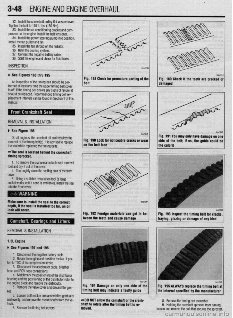
Fig. 188 CI ’ m
belt neeK ror premature panrng of the
Fig. 189 Check if the teeth are cracked or
IUIIII~U at IWSI
arly me me upper ommg oerr cover 1 1 damaged ,
I
is off. If the timina belt shows anv sians of failure. it INSPECTION
ti See Figures 188 thru 195
An inspection of the timing belt should be per-
I ^__^ -I ^I I---.-- I.-. II. .- I. . I I.
should be replaced. Recommended timing belt re:
placement intervals can be found in Section 1 of this
manual.
; REMOVAL&INSTALLATION
u See Figure 198
On all engines, the camshaft oil seal repuires the
Fig. 190 look for noticeable cracks or wear
removal of the timing belt(s). It is advised to replace
the seal while replacing the timing belts. on the belt face
*The seal is located behind the crankshaft
timino sorocket. I I Fig. 191 You may only have damage on one
side of the belt; if so, the guide-could be 1
the culprit
” .
1. To remove the seal use a suitable seal removal
tool and pry it out of the cover.
2. Thoroughly clean the sealing area of the front
fYi”f.V
i ““.“I. 3. Using a suitable installation tool (a large
socket works well if none is available), install the seal
into thr ? front cover,
EnI
Make surf! to install the seal to the correct
depth, if the seal is installed too far, an oil
leak will occur.
Fig. 192 Foreign materials can get in be-
REMOVAL &INSTALLATION
1 .!I Engine
+ See Figures 197 and 198
1. Disconnect the negative battery cable.
2. Rotate the engine and position the No. 1 pis-
ton to TDC of its compression stroke.
3. Disconnect the accelerator cable, breather
hose and PCV hose connections.
4. Matchmark the positionino of the distributor
housing and the positioning of thedistributor rotor to0
the engine block and remove the distributor.
5.
. Remove the valve cover and discard the gas- tween the teeth and cause damage
fraying, gla&g or damage of any kind
’
Itet.
6. Loosen both rocker arm assemblies gradually
and evenly, and remove the rocket shafts from the ve-
hicle.
7. Remove the timing belt covers.
c
Fig 194 Damage on only one side of the
timing belt may indicate a faulty guide Fig. 195 ALWAYS raplace the timing belt at
the interval soecified br the manufacturer
*DO NOT allow the camshaft or the crank-
shaft to rotate after the timing belt is re-
moved. 8. Remove the timing belt assembly.
9. Holding the camshaft sprocket from turning,
loosen and remove the bolt that secures the sprocket.
Page 120 of 408
ENGINEAND ENGINEOVERHAUL 3-59
Most of the cleaning process can be carried out
with common hand tools and readily available sol-
vents or solutions. Carbon deposits can be chipped
away using a hammer and a hard wooden chisel. Old
gasket material and varnish or sludge can usually be
removed using a scraper and/or cleaning solvent. Ex-
tremely stubborn deposits may require the use of a
power drill wrth a wire brush. If using a wire brush,
use extreme care around any critical machined sur-
faces (such as the gasket surfaces, bearing saddles,
cylinder bores, etc.). USE OF A WIRE BRUSH IS NOT
RECOMMENDED ON ANY ALUMINUM COMPO-
NENTS Always follow any safety recommendations
given by the manufacturer of the tool and/or solvent.
You should always wear eye protection during any
cleaning process involvrng scraping, chipping or
spraying of solvents.
An alternative to the mess and hassle of cleaning
the parts yourself is to drop them off at a local garage
or machine shop. They will, more than likely, have
the necessary equrpment to properly clean all of the
parts for a nominal fee.
Always wear eye protection during any clean-
ing process involving scraping, chipping or
spraying of solvents.
Remove any oil galley plugs, freeze plugs and/or
pressed-in bearings and carefully wash and degrease
all of the engine components including the fasteners
and bolts. Small parts such as the valves, springs,
etc., should be placed in a metal basket and allowed
to soak. Use pipe cleaner type brushes, and clean all
passageways in the components. Use a ring ex-
pander and remove the rings from the pistons. Clean
the piston ring grooves with a special tool or a piece
of broken ring Scrape the carbon off of the top of the
piston. You should never use a wire brush on the
pistons. After preparing all of the piston assemblies
in this manner, wash and degrease them again.
Use extreme care when cleaning around the
cylinder head valve seats. A mistake or slip
may cost you a new seat.
When cleaning the cylinder head, remove carbon
from the combustron chamber with the valves in-
stalled. This will avoid damaging the valve seats.
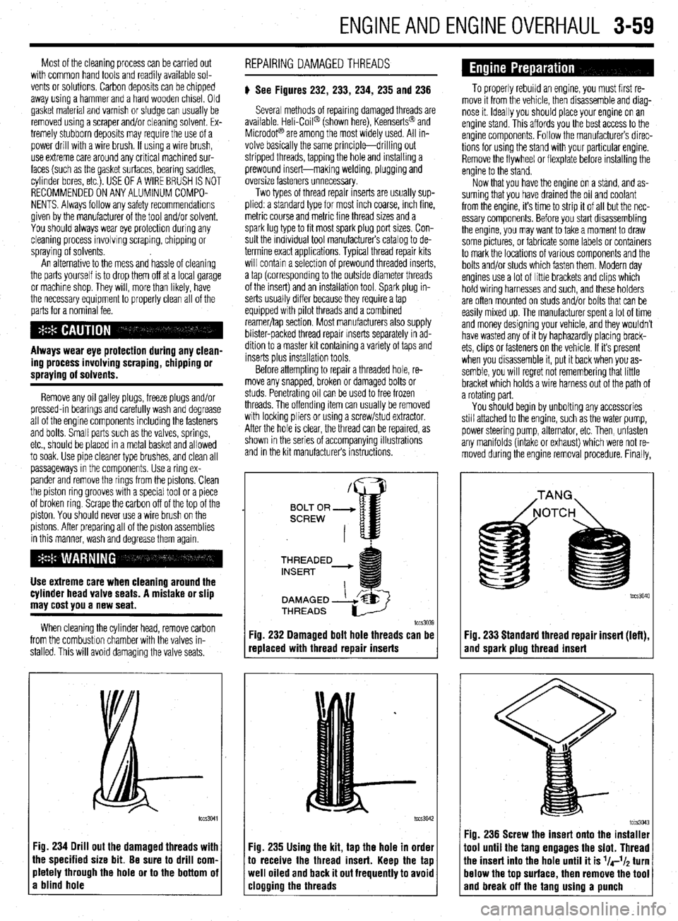
:ig. 234 Drill out the damaged threads with
he specified size bit. Be sure to drill corn.
rletely through the hole or to the bottom oi
I blind hole REPAIRING DAMAGEDTHREADS
# See Figures 232, 233, 234, 235 and 236
Several methods of repairing damaged threads are
available Heli-Coil@ (shown here), Keenserts@ and
Microdop are among the most widely used. All in-
volve basically the same principle-drilling out
stripped threads, tapping the hole and installing a
prewound insert-making welding, plugging and
oversize fasteners unnecessary.
Two types of thread repair inserts are usually sup-
plied: a standard type for most inch coarse, rnch fine,
metric course and metrrc fine thread sizes and a
spark lug type to fit most spark plug port sizes. Con-
sult the individual tool manufacturers catalog to de-
termine exact applications. Typical thread repair kits
will contain a selection of prewound threaded inserts,
a tap (corresponding to the outside diameter threads
of the insert) and an installation tool. Spark plug in-
serts usually differ because they require a tap
equipped wrth pilot threads and a combined
reamer/tap section. Most manufacturers also supply
blister-packed thread repair Inserts separately in ad-
dition to a master kit containing a variety of taps and
inserts plus installation tools
Before attempting to repair a threaded hole, re-
move any snapped, broken or damaged bolts or
studs. Penetrating oil can be used to free frozen
threads. The offending item can usually be removed
with locking pliers or using a screw/stud extractor.
After the hole is clear, the thread can be reparred, as
shown in the series of accompanying illustrations
and in the krt manufacturers instructions.
THREADED
lCCS3039
replaced with thread repair inserts
:ig. 235 Using the kit, tap the hole in order
o receive the thread insert. Keep the tap
veil oiled and back it out frequently to avoid
:logging the threads
To properly rebuild an engine, you must first re-
move it from the vehicle, then disassemble and diag-
nose it. Ideally you should place your engine on an
engine stand. This affords you the best access to the
engine components. Follow the manufacturers direc-
tions for using the stand with your particular engine.
Remove the flywheel or flexplate before installing the
engine to the stand.
Now that you have the engine on a stand, and as-
suming that you have drained the oil and coolant
from the engine, it’s time to strip it of all but the nec-
essary components. Before you start disassembling
the engine, you may want to take a moment to draw
some pictures, or fabricate some labels or containers
to mark the locations of various components and the
bolts and/or studs which fasten them. Modern day
engines use a lot of little brackets and clips which
hold wiring harnesses and such, and these holders
are often mounted on studs and/or bolts that can be
easily mixed up. The manufacturer spent a lot of time
and money designing your vehicle, and they wouldn’t
have wasted any of it by haphazardly placing brack-
ets, clips or fasteners on the vehicle. If it’s present
when you disassemble it, put it back when you as-
semble, you will regret not remembering that little
bracket which holds a wire harness out of the path of
a rotating part.
You should begin by unbolting any accessories
still attached to the engine, such as the water pump,
power steering pump, alternator, etc. Then, unfasten
any manifolds (intake or exhaust) which were not re-
moved during the engine removal procedure. Finally,
Fig. 233 Standard thread repair insert (left),
and spark plug thread insert
im3043 Fig. 236 Screw the insert onto the installer
1001 until the tang engages the slot. Thread
‘he insert into the hole until it is l/4-l/~ turn
lelow the top surface, then remove the tool
and break off the tano usina a uunch
Page 161 of 408
.
4-18 DRIVEABILITYAND EMISSIONS CONTROLS
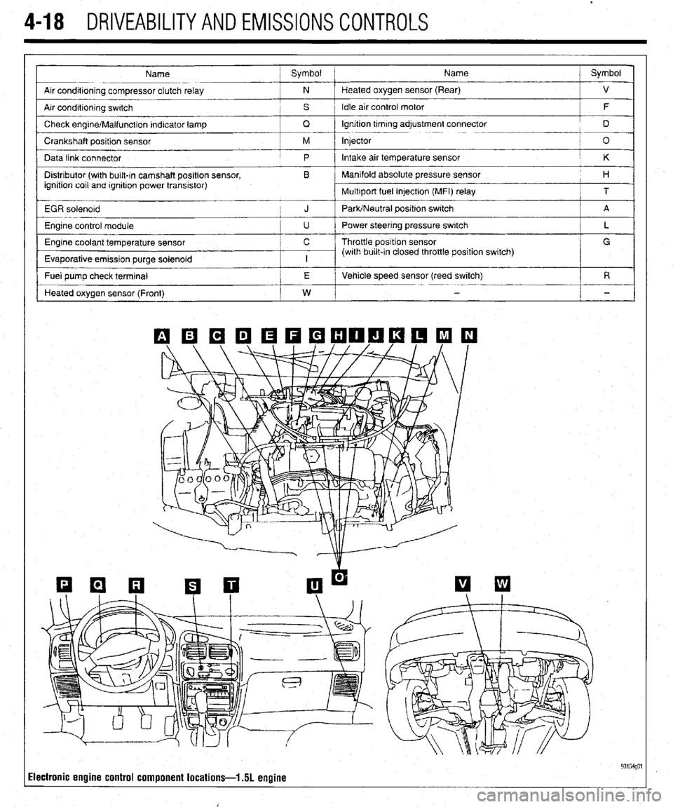
Name ; Symbol Name j Symbol
I
Arr conditioning compressor clutch relay ; N Heated oxygen sensor (Rear)
j ”
Air condrtioning swatch , s 1 Idle air control motor
/ F
/
Check engrne/Malfunction Indicator lamp
/ Q lgnrtion trmrng adjustment connector
j D
Crankshaft position sensor / M Injector
! O
Data link connector
j p Intake air temperature sensor / K
Distributor (wrth bulk-in camshaft position sensor, , B Manifold absolute pressure sensor
ignition coil and rgnrtron power transistor) I 1 H
Multrport fuel in]ectron (MFI) relay
i T
EGR solenord
i J PaWNeutral positron switch j A
Engine control module
I u I Power steering pressure switch
Engine coolant temperature sensor c / Throttle position sensor
Evaporative emission purge solenoid
I I I (with burl&In closed throttle position switch) / L _
/ G
I
I
- Fuel pump check terminal /
I j E i Vehicle speed sensor (reed switch)
/ R
Heated oxygen sensor (Front)
I w I
i -
Ilectronic engine control component locations-l 51 engine 93154go1
Page 162 of 408
DRIVEABILITYAND EMISSIONS CONTROLS 4-19
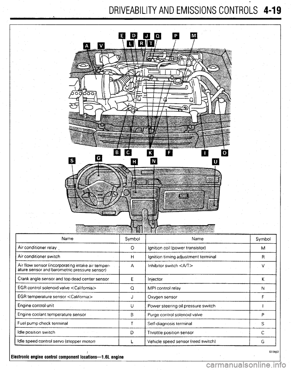
Name
Air conditroner relay
Air condrtroner switch
Air flow sensor (rncorporatrng Intake arr temper-
ature sensor and barometric pressure sensor) Symbol Name
Symbol
0 ignition cot1 (power transrstor)
M
H lgnrtion trmtng adjustment terminal
R
A Inhibitor switch
V
Crank angle sensor and top dead center sensor
E Injector K
1 EGR control solenord valve
1 Q 1 MPI control relay
1 N 1
EGR temperature sensor
Engine control unit
Engine coolant temperature sensor
I Fuel pump check terminal J Oxygen sensor F
U Power steering 011 pressure switch I
0 Purge control solenord valve
P
1 T I Self-dragnosis terminal
I s I
I idle posrtron swatch
1 D 1 Throttle positron sensor I c I
Idle speed control servo (stepper motor)
L Vehicle speed sensor (reed swatch)
G
ilectronic engine control component lochions- .6L enuine 93154go;
Page 163 of 408
4-20 , DRIVEABILITYAND EMISSIONS CONTROLS
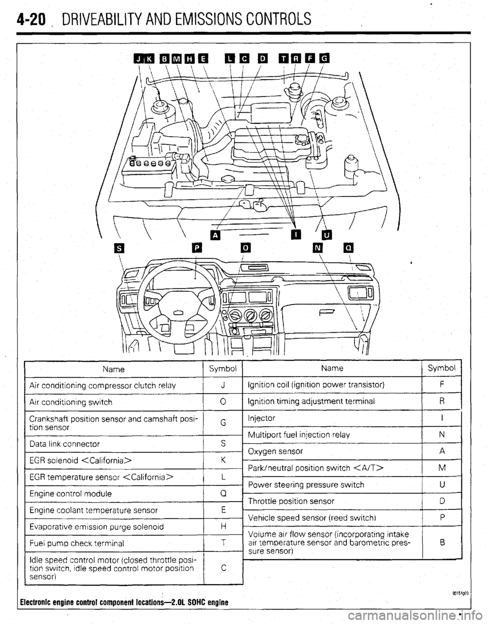
Name Symbol Name Symbol
Air conditioning compressor clutch relay J Ignition coil (ignition power transistor) F
Air conditlonrng switch 0 Ignition trming adjustment terminal R
Crankshaft positron sensor and camshaft posi- Injector I
tion sensor G
~ Multiport fuel injection relay N
Data link connector s ’
- Oxygen sensor A
EGR solenoid
~ Park/neutral positron switch M
EGR temperature sensor
_ Power steering pressure switch
U
Engine control module Q
~ Throttle position sensor
D
Engrne coolant temperature sensor E
Vehicle speed sensor (reed switch) P
Evaporative emrsslon purge solenoid H -
Volume air flow sensor (incorporating intake
Fuel pump check terminal T arr temperature sensor and barometric pres- B
- sure sensor)
Idle speed control motor (closed throttle POW
tron swatch, tdle speed control motor positron
sensor)
! c
93154go: Electronic engine control component locations-2.01 SOHC engine
Page 165 of 408
4-22 DRIVEABILITYAND EMISSIONS CONTROLS
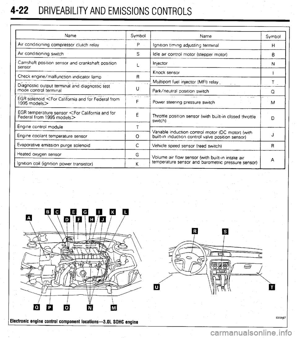
Name Symbol
Name Symbol
I
Arr condrttontng compressor clutch relay
P lgnrtton trmrng adjustrng terminal
H
Air condrbonrng swrtch
S Idle arr control motor (stepper motor)
B
Camshaft posrtron sensor and crankshaft posrtron
Injector
N
sensor L
~ Knock sensor
Check engrne/malfunctton rndtcator lamp I
R -
I D~agnostrc output termtnal and dtagnostrc test F- Mujttport fuel qector (MFI) relay _
T
mode control termrnal U
Park/neutral oosrtron swatch
Q
EGR solenoid
1995 models> F
Power steering pressure swatch M
I
EGR temperature sensor
Throttle posrtlon sensor fwrth burlt-In closed throttle
, swrtch)
Engrne control module
Engine coolant temperature sensor
Evaporatrve emrssron purge solenord T
0 Variable tnductton control motor (DC motor) (wrth
burlt-tn rnductron control valve posrtron sensor) J
C Vehrcle speed sensor (reed swatch) R
Heated oxygen sensor
Ignition cot1 (ionrtron Dower transistor) G
Volume arr flow sensor (with burlt-In Intake arr
K temperature sensor and barometric pressure sensor)
I I A
ilectronic engine control component locations-3.01 SOHC engine 93154go7
Page 167 of 408
.
4-24 DRIVEABILITYAND EMISSIONS CONTROLS
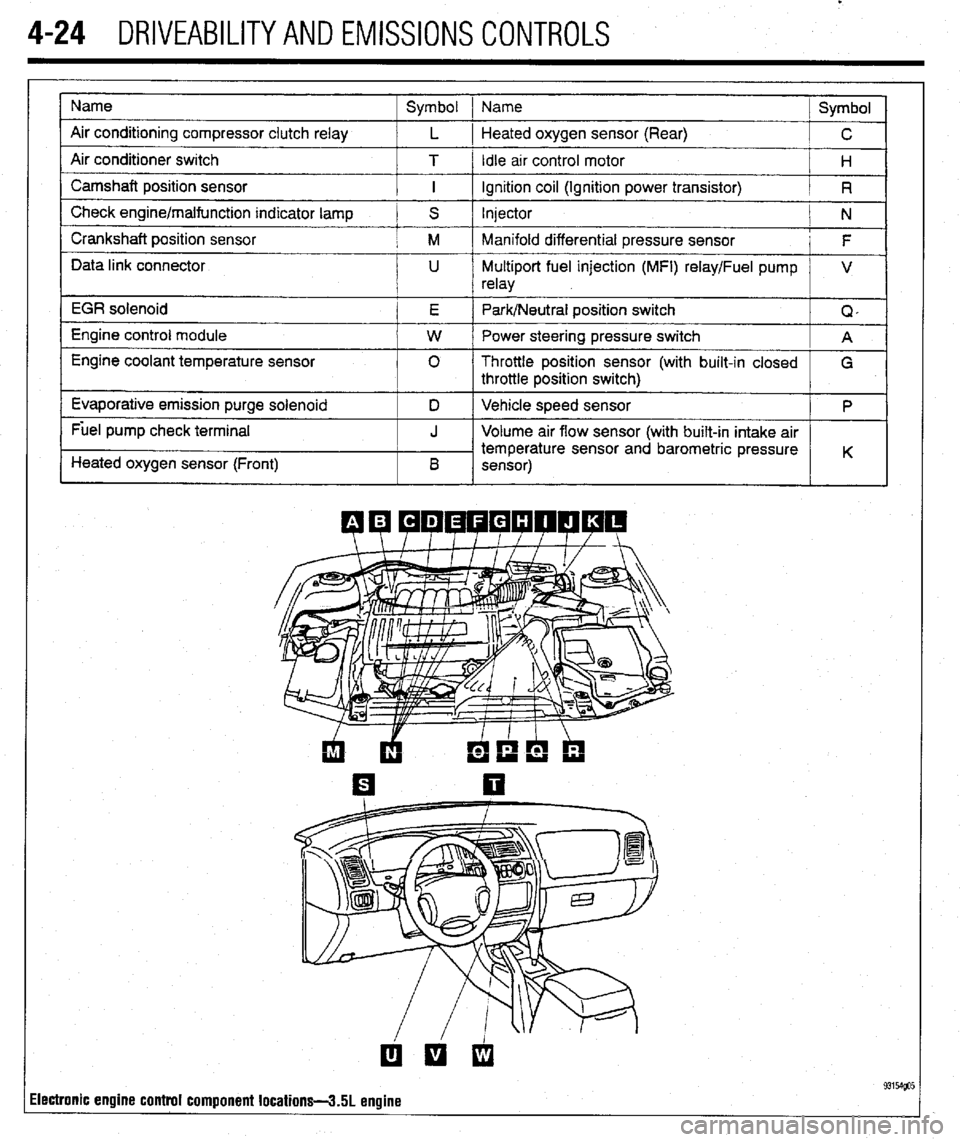
Name
Air conditioning compressor clutch relay
Air conditioner switch
Camshaft position sensor
Check engine/malfunction indicator lamp
Crankshaft position sensor
Data link connector
EGR solenoid
Engine control module
Engine coolant temperature sensor
Evaporative emission purge solenoid
Fuel pump check terminal
Heated oxygen sensor (Front) Symbol 1 Name
Symbol
L 1 Heated oxygen sensor (Rear)
C
T / Idle arr control motor
H
I ignition coil (Ignition power transistor)
R
S Injector
N
M Manifold differential pressure sensor
F
U Multiport fuel injection (MFI) relay/Fuel pump V
relay
E Park/Neutral position switch
Q,
W Power steering pressure switch
A
0 Throttle position sensor (with built-in closed
G
throttle position switch)
D Vehicle speed sensor
P
J Volume air flow sensor (with built-in intake air
temperature sensor and barometric pressure
B K
sensor)
ilectronic engine control component locations-3.51 engine
Page 168 of 408
DRIVEABILITYAND EMISSIONS CONTROLS 4-25
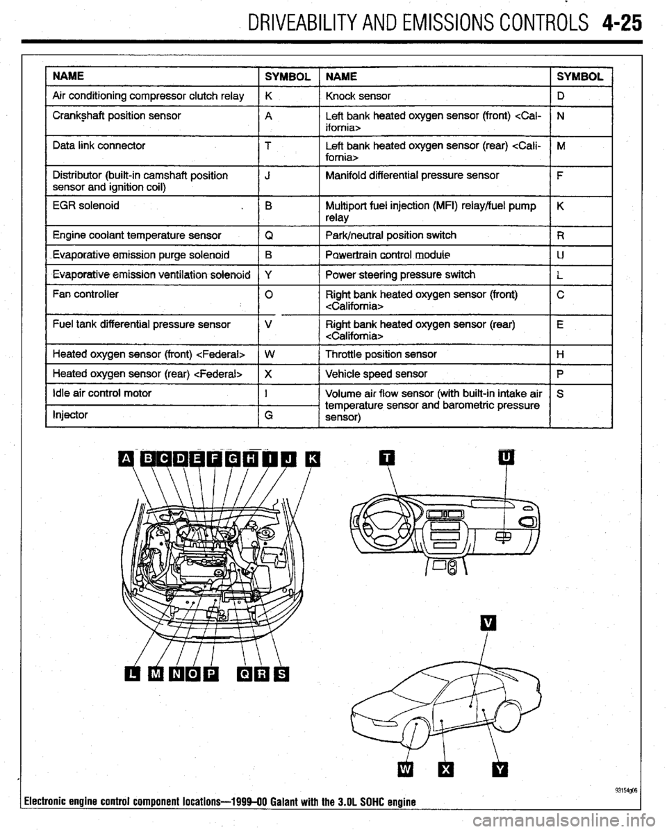
NAME
SYMBOL NAME SYMBOL
Air conditioning compressor clutch relay K
Knock sensor D
I Crankshaft position sensor
A Left bank heated oxygen sensor (front)
I I
Data link connector T Left bank heated oxygen sensor (rear)
I Distributor (built-in camshaft position
I J Manifold differential pressure sensor
I F
sensor and ignition coil)
I
EGR solenoid . B Multiport fuel injection (MFI) relay/fuel pump K
relay
1 Engine coolant temperature sensor
IQ 1 Park/neutral position switch IR
Euaporatiue.emission purge solenoid B
Powertraincontrol module LJ
l Evaporatiw5+eiiission ventilation solenoid Y
I Powersteering pressure switch
L
Fan controller 0 Right bank heated oxygen sensor (front) C
Fuel tank differential pressure sensor V Right bank heated oxygen sensor (rear) E
Heated oxygen sensor (front)
I
1 Heated oxygen sensor (rear)
Ip I
Idle air control motor
Injector I
G Volume air flow sensor (with built-in intake air S
temperature sensor and barometric pressure
sensor)
I I
93154@3 lectronic engine control component locations-199940 Galant with the 3.OL SOHC engine