Page 257 of 406
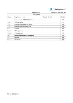
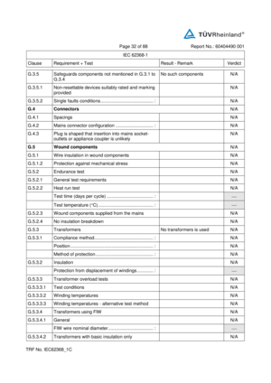
Page 44 of 88 Report No. : 60404489 001
IEC 62368 - 1
Clause Requirement + Test Result - Remark Verdict
TR F No. IEC62368_1 C
Relevant tests of IEC 60529 or Y.5.3 .................... : N/A
Y.5.3 Water sp ray test N/A
Y.5.4 Protection from plants and vermin N/A
Y.5.5 Protection from excessive dust N/A
Y.5.5.1 General N/A
Y.5.5.2 IP5X equipment N/A
Y.5.5.3 IP6X equipment N/A
Y.6 Mechanical strength of enclosures
N/A
Y.6.1 General N/A
Y.6.2 Im pact test ................................ ............................. : N/A
Page 258 of 406

Page 45 of 88 Report No. : 60404489 001
IEC 62368 - 1
Clause Requirement + Test Result - Remark Verdict
TR F No. IEC62368_1 C
5.2 TABLE: Classification of electrical energy sources
P
Supply
Voltage Location (e.g.
circuit
designation) Test conditions Parameters ES
Class
U (V) I (mA) Type 1 )
Additional
Info 2 )
12 V d.c. Input power Normal 12 - - - ES1
S upplementary information:
1) Type: Steady state (SS), Capacitance (CP), Single pulse (SP), Repetitive pulses (RP) , etc.
2) Additional Info: Frequency, Pulse duration, Pulse off time, Capacitance value , etc.
5.4.1.8 TABLE: Working voltage measurement
N/A
Location RMS voltage
(V) Peak voltage
(V) Frequency
(Hz) Comments
Supplementary information:
5.4.1.10.2 TABLE: Vicat softening temperature of thermoplastics
N/A
Method ................................ ................................ ............................ : ISO 306 / B50
Object/ Part No./Material Manufacturer/trademark Thickn ess (mm) T softening (°C)
Supplementary information:
5.4.1.10.3 TABLE: Ball pressure test of thermoplastics
N/A
Allowed impression diameter (mm) ................................ ............... :
2 mm
Object/Part No./Material Manufacturer/trademark Thickness (mm) Test
temperature ( C) Impre ssion
diameter (mm)
Supplementary information:
Page 259 of 406

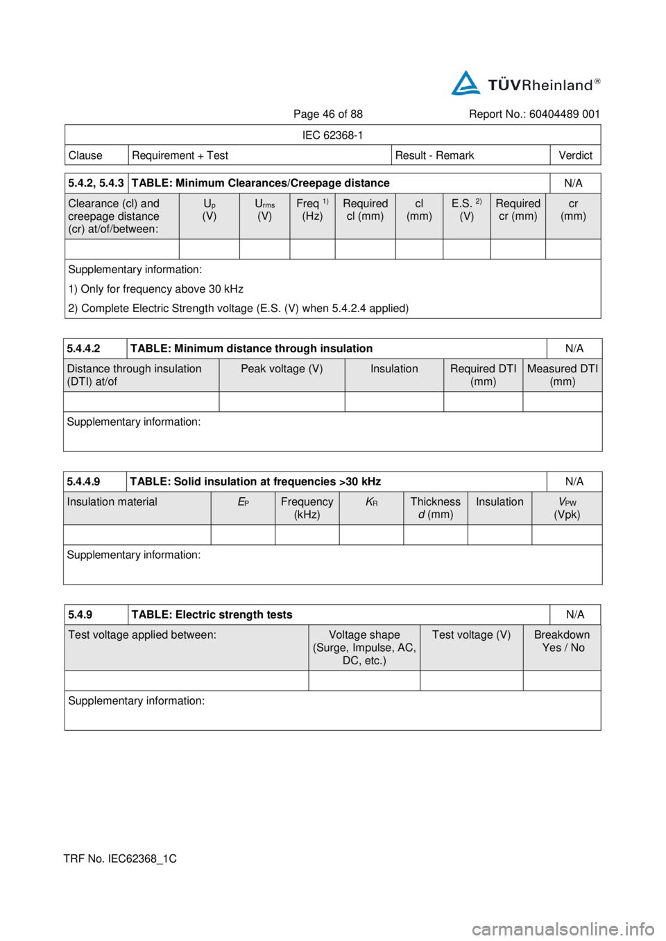
Page 46 of 88 Report No. : 60404489 001
IEC 62368 - 1
Clause Requirement + Test Result - Remark Verdict
TR F No. IEC62368_1 C
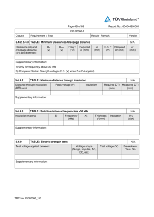
5.4.2, 5.4.3 TABLE: Minimum Clearances/Creepage distance
N/A
Clearance (cl) and
creepage distance
(cr) at/of/between: U
p
(V) U
rms
(V) Freq 1 )
(Hz) Required
cl (mm) cl
(mm) E.S. 2)
(V)
Required
cr (mm) cr
(mm)
Supplementary information:
1) O nly for frequency above 30 kHz
2) Complete Electric Strength voltage (E.S. (V) when 5.4.2.4 applied)
5.4.4.2 TABLE: Minimum distance through insulation
N/A
Distance through insulation
(DTI) at/of Peak voltage (V) Insulation Required DTI
(mm) Measured DTI
(mm)
Supplementary information:
5.4.4.9 TABLE: Solid insulation at frequencies >30 kHz
N/A
Insulation material E
P
Frequency
(kHz) K
R
Thickness
d (mm) Insulation V
PW
(Vpk)
Supplementary information:
5.4.9 TABLE: Electric strength tests
N/A
Test voltage applied between: Voltage shape
(Surge, Impulse, AC,
DC, etc.) Test voltage (V) Breakdown
Yes / No
Supplementary information:
Page 260 of 406

Page 47 of 88 Report No. : 60404489 001
IEC 62368 - 1
Clause Requirement + Test Result - Remark Verdict
TR F No. IEC62368_1 C
5.5.2.2 TABLE: Stored discharg e on capacitors
N/A
Location Supply voltage (V) Operating and fault
condition 1)
Switch
position Measured
voltage
(Vpk) ES Class
Supplementary information:
X - capacitors installed for testing:
bleeding resistor rating:
ICX:
1) Normal operating condition (e.g., normal operation, or open fuse), SC= short circuit, OC= open circuit
5.6.6 TABLE: Resistance of protective conductors and terminations
N/A
Location Test current
(A) Duration
(min) Voltage drop
(V) Resi stance
( Ω )
Supplementary information:
5.7.4 TABLE: Unearthed accessible parts
N/A
Location Operating and
fault conditions Supply
Voltage (V) Parameters ES
class
Voltage
(V
rms or V
pk ) Current
(A
rms or A
pk ) Freq.
(Hz)
S upplementary information:
Abbreviation: SC= short circuit; OC= open circuit
5.7.5 TABLE: Earthed accessible conductive part
N/A
Supply voltage (V) ........................... :
Phase(s) ................................ ......... : [] Single Phase; [ ] Three Phase : [ ] Delta [ ] W ye
Power Distribution System ............. : TN TT IT
Location Fault Condition No in IEC
60990 clause 6.2.2 Touch current
(mA) Comment
Supplementary Information:
Page 261 of 406

Page 48 of 88 Report No. : 60404489 001
IEC 62368 - 1
Clause Requirement + Test Result - Remark Verdict
TR F No. IEC62368_1 C
5.8 TABLE: Backfeed safeguard in battery backed up s upplies
N/A
Location Supply
voltage (V) Operating and fault
condition Time (s) Open - circuit
voltage (V) Touch
current (A) ES Class
Supplementary information:
Abbreviation: SC= short circuit, OC= open circuit
6.2.2 TABLE: Power source circuit cl assifications
P
Location Operating and
fault condition Voltage (V) Current (A) Max.
Power 1)
(W) Time (S) PS class
Mains part - 1 2 V d.c. - - - PS3
(Declared)
Speaker
output Worst - case fault 7. 44 1.8 6
( calculated ) 13. 84 3 PS1
CN501
(49, GND) /
LCD PMR Worst - case fault 1.70 0.0 1 0.0 2 3 PS1
CN951
(51, GND) /
KEY_POW ER Worst - case fault 3.2 4 0.10 0.3 2 3 PS1
CN951
(17,GND) Worst - case fault 3.3 1 3.9 2 13. 1 0 3 PS1
CN951
(1, GND) /
SYS 5.2 Worst - case fault 4. 30 8. 2 0 35.30 5
PS2
CN951
(15, GND) /
VCC *) W orst - case fault 7.6 1 12. 6 0 95.90 5
PS2
Supplementary information:
Abbreviation: SC= short circuit; OC= open circuit
1) Measured after 3 s for PS1 and measured after 5 s for PS2 and PS3.
PS3: All combustible materials except for PS2 and PS1 parts below.
PS2: Monitor circuit and keyboard circuit.
*) LCD module and keyboard power line .
Page 262 of 406

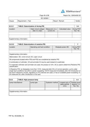
Page 49 of 88 Report No. : 60404489 001
IEC 62368 - 1
Clause Requirement + Test Result - Remark Verdict
TR F No. IEC62368_1 C
6.2.3.1 TABLE: Determination of Arcing PIS
N/A
Location Open circuit voltage
after 3 s (V pk ) Measured r.m.s
current (A)
Calculated value
Arcing PIS?
Yes / No
S upplementary information:
6.2.3.2 TABLE: Determination of resistive PIS
P
Location Operating and fault condition Dissipate power (W) Arcing PIS?
Yes / No
Supplementary information:
Abbreviation: SC= short circuit; OC= open circuit
All components l ocated within PS3 and PS2 are considered as resistive PIS.
A combination of voltmeter, VA and ammeter IA may be used instead of a wattmeter.
If a separate voltmeter and ammeter are used, the product of (VA x IA) is used to determine Resistive PIS
classific ation.
A Resistive PIS: (a) dissipates more than 15 W, measured after 30 s of normal operation, or (b) under
single fault conditions has either a power exceeding 100 W measured immediately after the introduction of
the fault if electronic circuits, regulat ors or PTC devices are used, or has an available power exceeding 15
W measured 30 s after introduction of the fault.
8.5.5 TABLE: High pressure lamp
N/A
Lamp manufacturer Lamp type Explosion method Longest axis of
glass particle
(mm) Particle found
bey ond 1 m
Yes / No
Supplementary information:
Page 263 of 406

Page 50 of 88 Report No. : 60404489 001
IEC 62368 - 1
Clause Requirement + Test Result - Remark Verdict
TR F No. IEC62368_1 C
9.6 TABLE: Temperature measurements for wireless power transmitters
N/A
Supply voltage (V) ................................ .......... :
Max. transmit power of transmitter (W) .......... :
Foreign objects w/o receiver and
direct contact with receiv er and
direct contact with receiver and at
distance of 2 mm with receiver and at
distance of 5 mm
Object
( o
C) Ambient
( o
C) Object
( o
C) Ambient
( o
C) Object
( o
C) Ambient
( o
C) Object
( o
C) Ambient
( o
C)
Supplementary information:
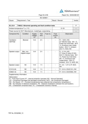
5.4.1.4 ,
9.3 , B.1.5 ,
B.2.6 TABLE: Temperature measurements
P
Supply voltage (V) ................................ .......... : 14.4 V
d.c. 14.4 V
d.c. 14.4 V
d.c.
Ambient temperature during test T
amb ( C) .... : 20.9 25 1)
70 2)
Maximum measured temperature T of part/at:
T ( C) Allowed
T
max ( C)
1. Display PCB near IC100 43.1 - 92.2 130
2. Display panel body (Not accessible) 44.6 - 93.7 -
3. Connector body (CN310) 41.3 - 90.4 -
4. PCB near SD card slot 49.3 - 98.4 130
5. Main PCB near CN150 47.9 - 97.0 130
6. Main PCB near IC 402 68.3 - 117.4 130
7. Main PCB near L304 45.6 - 94.7 130
8. Main to Display connector body (CN951) 51.3 - 100.4 -
9. PCB near BD7820 61.1 - 110.2 130
10. PCB near CN151 56.5 - 105.6 130
11. Amp IC body (IC163) 63.4 - 112.5 -
12. PCB near C298 58.4 - 107.5 130
13 . Main to Antenna connector body (CN990) 54.4 - 103.5 -
14. Antenna PCB near IC182 64.2 - 113.3 130
15. Monitor body 36.3 40.4 - 71
Page 264 of 406

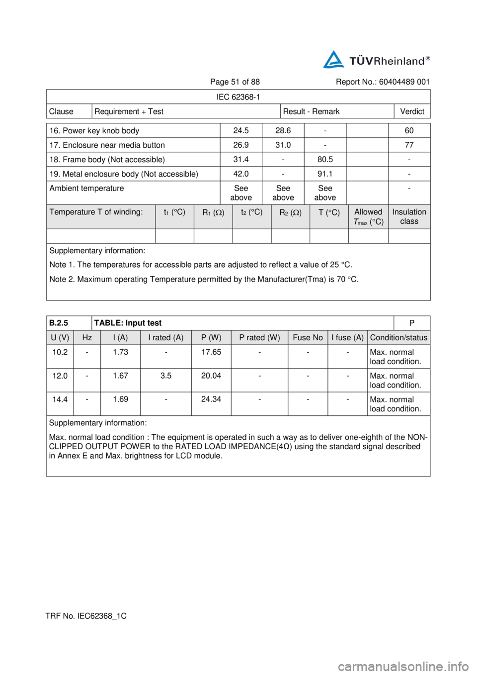
Page 51 of 88 Report No. : 60404489 001
IEC 62368 - 1
Clause Requirement + Test Result - Remark Verdict
TR F No. IEC62368_1 C
16. Power key knob body 24.5 28.6 - 60
17. Enclosure near media button 26.9 31.0 - 77
18. Frame body (Not accessib le) 31.4 - 80.5 -
19. Metal enclosure body (Not accessible) 42.0 - 91.1 -
Ambient temperature See
above See
above See
above -
Temperature T of winding: t
1 (°C)
R
1 ( ) t
2 (°C)
R
2 ( ) T ( C) Allowed
T
max ( C) Insulation
class
Supplementary in formation:
Note 1. The temperatures for accessible parts are adjusted to reflect a value of 25 °C .
Note 2. Maximum operating Temperature pe rmitted by the Manufacturer(Tma) is 70 C .
B.2.5 TABLE: Input test
P
U (V) Hz I (A) I rated (A) P (W) P rated (W ) Fuse No I fuse (A) Condition/status
10.2 - 1.73 - 17.65 - - -
Max. normal
load condition.
12.0 - 1.67 3.5 20.04 - - -
Max. normal
load condition.
14.4 - 1.69 - 24.34 - - -
Max. normal
load condition.
Supplementary information:
Max. normal load condit ion : The equipment is operated in such a way as to deliver one - eighth of the NON -
CLIPPED OUTPUT POWER to the RATED LOAD IMPEDANCE ( 4Ω ) using the standard signal described
in Annex E and Max. brightness for LCD module.