Page 289 of 406

Page 76 of 88 Report No. : 60404489 001
IEC 62368 - 1_ATTACHMENT 2
Clause Requirement + Test Result - Remark Verdict
TR F No. IEC62368_1 C
10.6.6.1 Corded listening devices with analogue input
With 94 dB L Aeq acoustic pressure output of the
listening device, and with the volume and sound
settings in the listening device (for example, built - in
volume leve l control, additional sound features like
equalization, etc.) set to the combination of positions
that maximize the measured acoustic output, the
input voltage of the listening device when playing the
fixed “programme simulation noise” as described in
EN 5 0332 - 1 shall be ≥ 75 mV.
NOTE The values of 94 dB and 75 mV correspond with 85 dB
and 27 mV or 100 dB and 150 mV. N/A
10.6.6.2 Corded listening devices with digital input
With any playing device playing the fixed
“programme simulation noise” described in EN
50332 - 1, a nd with the volume and sound settings in
the listening device (for example, built - in volume
level control, additional sound features like
equalization, etc.) set to the combination of positions
that maximize the measured acoustic output, the
L Aeq , T acousti c output of the listening device shall be
≤ 100 dB with an input signal of - 10 dBFS. N/A
10.6.6.3 Cordless listening devices
In cordless mode,
– with any playing and transmitting device playing
the fixed programme simulation noise described in
EN 50332 - 1; and
– respecting the cordless transmiss ion standards,
where an air interface standard exists that specifies
the equivalent acoustic level; and
– with volume and sound settings in the receiving
device (for example, built - in volume level control,
additional sound features like equalization, etc.) set
to the combination of positions that maximize the
measured acoustic output for the above mentioned
programme simulation noise, the L Aeq , T acoustic
output of the listening device shall be ≤ 100 dB with
an input signal of - 10 dBFS. N/A
10.6.6.4 Measurement method
Measurements shall be made in accordance with EN
50332 - 2 as applicable. N/A
3
Modification to the whole document
P
Page 290 of 406
Page 77 of 88 Report No. : 60404489 001
IEC 62368 - 1_ATTACHMENT 2
Clause Requirement + Test Result - Remark Verdict
TR F No. IEC62368_1 C
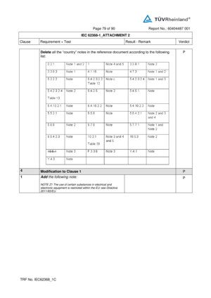
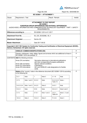
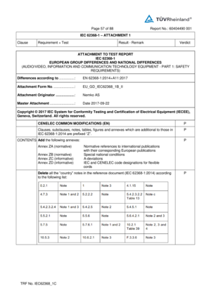
Delete all the “country” notes in the reference document ac cording to the following
list:
P
4
Modification to Clause 1
P
1 Add the following note:
NOTE Z1 The use of certain substances in electrical and
electronic equipment is restricted within the EU: see Directive
2011/65/EU. P
Page 291 of 406

Page 78 of 88 Report No. : 60404489 001
IEC 62368 - 1_ATTACHMENT 2
Clause Requirement + Test Result - Remark Verdict
TR F No. IEC62368_1 C
5
Modification to 4.Z1
N /A
4.Z1 Add the following new subclause after 4.9:
To protect against excessive current, short - circuits
and earth faults in circuits connected to an a.c.
mains , protective devices shall be included either as
integral parts of the equipment or as parts of the
building installation, subject to the following, a), b)
and c):
a) except as detailed in b) and c), protective devices
necessary to comply with the requirements of B.3.1
and B.4 shall be included as parts of the equipment;
b) for components in series with the mains input to
the equipment such as the supply cord, appliance
coupler, r.f.i. filter and switch, short - circuit and earth
fault protection may be provided by protective
devices in the building installation;
c) it is permitted for pluggable equipm ent type B or
permanently connected equipment , to rely on
dedicated overcurrent and short - circuit protection in
the building installation, provided that the means of
protection, e.g. fuses or circuit breakers, is fully
specified in the installation instruc tions.
If reliance is placed on protection in the building
installation, the installation instructions shall so state,
except that for pluggable equipment type A the
building installation shall be regarded as providing
protection in accordance with the ra ting of the wall
socket outlet. N/A
6
Modification to 5.4.2.3.2.4
N/A
5.4.2.3.2.4 Add the following to the end of this subclause:
The requirement for interconnection with external
circuit is in addition given in EN 50491 - 3:2009. N/A
7
Modification to 10.2.1
N/A
10.2.1
Add the following to c)
and d)
in table 39:
For additional requirements, see 10.5.1. N/A
Page 292 of 406

Page 79 of 88 Report No. : 60404489 001
IEC 62368 - 1_ATTACHMENT 2
Clause Requirement + Test Result - Remark Verdict
TR F No. IEC62368_1 C
8
Modification to 10.5.1
N/A
10.5.1 Add the following after the first paragraph:
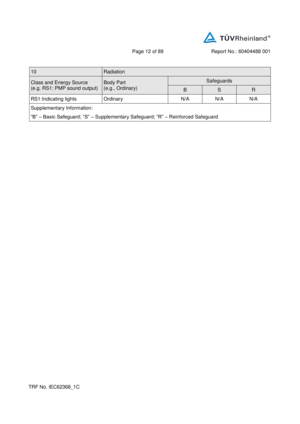
For RS 1 compliance is checked by measurement
under the fol lowing conditions:
In addition to the normal operating conditions, all
controls adjustable from the outside by hand, by any
object such as a tool or a coin, and those internal
adjustments or pre - sets which are not locked in a
reliable manner, are adjusted so as to give
maximum radiation whilst maintaining an intelligible
picture for 1 h, at the end of which the measurement
is made.
NOTE Z1 Soldered joints and paint lockings are examples of
adequate locking.
The dose - rate is determined by means of a radia tion
monitor with an effective area of 10 cm², at any point
10 cm from the outer surface of the apparatus.
Moreover, the measurement shall be made under
fault conditions causing an increase of the high
voltage, provided an intelligible picture is maintain ed
for 1 h, at the end of which the measurement is
made.
For RS1, the dose - rate shall not exceed 1 μSv/h
taking account of the background level.
NOTE Z2 These values appear in Directive 96/29/Euratom of 13
May 1996. N/A
9
Modification to G.7.1
N/A
G.7.1 Add the following note:
NOTE Z1 The harmonized code designations corresponding to
the IEC cord t ypes are given in Annex ZD. N/A
Page 293 of 406

Page 80 of 88 Report No. : 60404489 001
IEC 62368 - 1_ATTACHMENT 2
Clause Requirement + Test Result - Remark Verdict
TR F No. IEC62368_1 C
10 Modification to Bibliography
N/A
Add the following notes for the standards indicated:
N/A
11 ADDITION OF ANNEXES
N/A
ZB ANNEX ZB, SPECIAL NATIONAL CONDITIONS (EN )
N/A
4.1.15 Denmark, Finland, Norway and Swede n
To the end of the subclause the following is
added:
Class I pluggable equipment type A intended
for connection to other equipment or a
network shall, if safety relies on connection to
reliable earthing or if surge suppressors
are connected between the n etwork terminals
and accessible parts, have a marking stating
that the equipment shall be connected to an
earthed mains socket - outlet.
The marking text in the applicable countries shall
be as follows:
In Denmark : “Apparatets stikprop skal tilsluttes
en s tikkontakt med jord som giver forbindelse til
stikproppens jord.”
In Finland : "Laite on liitettä vä suojakoskettimilla
varustettuun pistorasiaan"
In Norway : “Apparatet må tilkoples jordet
stikkontakt”
In Sweden : “Apparaten skall anslutas till jordat
uttag” N/A
Page 294 of 406

Page 81 of 88 Report No. : 60404489 001
IEC 62368 - 1_ATTACHMENT 2
Clause Requirement + Test Result - Remark Verdict
TRF No. IEC62368_1 C
4.7.3 United Kingdom
To the end of the subclause the following is added:
The torque test is performed using a socket - outlet
complying with BS 1363, and the plug part shall be
assessed to the relevant clauses of BS 1363. Also
see Annex G.4.2 of thi s annex N/A
5.2.2.2 Denmark
After the 2nd paragraph add the following:
A warning (marking safeguard) for high touch
current is required if the touch current exceeds the
limits of 3,5 mA a.c. or 10 mA d.c. N/A
5.4.11.1
and
Annex G Finland and Sweden
To the end of the subclause the following is added:
For separation of the telecommunication network
from earth the following is applicable:
If this insulation is solid, including insulation forming
part of a component, it shall at least
consist of either
• two layers of thin sheet material, each of which
shall pass the electric strength test below, or
• one layer having a distance through insulation of
at least 0,4 mm, which shall pass the electric
strength test below.
If this insulation forms part of a semiconductor
component (e.g. an optocoupler), there is no
distance through insulation requirement for the
insulation consisting of an insulating compound
completely filling the casing, so that clearances and
creepage distances do not exist, if the co mponent
passes the electric strength test in accordance with
the compliance clause below and in addition
• passes the tests and inspection criteria of 5.4.8
with an electric strength test of 1,5 kV multiplied
by 1,6 (the electric strength test of 5.4.9 sh all be
performed using 1,5 kV),
and
• is subject to routine testing for electric strength
during manufacturing, using a test voltage of 1,5
kV.
It is permitted to bridge this insulation with a
capacitor complying with EN 60384 - 14:2005,
subclass Y2. N/A
Page 295 of 406

Page 82 of 88 Report No. : 60404489 001
IEC 62368 - 1_ATTACHMENT 2
Clause Requirement + Test Result - Remark Verdict
TRF No. IEC62368_1 C
A capacitor classified Y3 according to EN 60384 -
14:2005, may bridge this insulation under
the following conditions:
• the insulation requirements are satisfied by
having a capacitor classified Y3 as defined by EN
60384 - 14, which in addition to the Y3 tes ting, is
tested with an impulse test of 2,5 kV defined in
5.4.11;
• the additional testing shall be performed on all the
test specimens as described in EN 60384 - 14;
the impulse test of 2,5 kV is to be performed before
the endurance test in EN 60384 - 14, in the sequence
of tests as described in EN 60384 - 14.
5.5.2.1 Norway
After the 3rd paragraph the following is added:
Due to the IT power system used, capacitors are
required to be rated for the applicable line - to - line
voltage (230 V). N/A
5.5.6 Finland, Norway and Sweden
To the end of the subclause the following is added:
Resistors used as basic safeguard or bridging
basic insulation in class I pluggable equipment
type A shall comply with G.10.1 and the test of
G.10.2. N/A
5.6.1 Denmark
Add to the end of the subclause
Due to many existing installations where the socket -
outlets can be protected with fuses
with higher rating than the rating of the socket -
outlets the protection for pluggable
equipment type A shall be an integral part of the
equi pment.
Justification:
In Denmark an existing 13 A socket outlet can be
protected by a 20 A fuse. N/A
5.6.4.2.1 Ireland and United Kingdom
After the indent for pluggable equipment type A ,
the following is added:
– the protective current rating is taken t o be 13 A,
this being the largest rating of fuse used in the
mains plug. N/A
Page 296 of 406

Page 83 of 88 Report No. : 60404489 001
IEC 62368 - 1_ATTACHMENT 2
Clause Requirement + Test Result - Remark Verdict
TRF No. IEC62368_1 C
5.6.4.2.1 France
After the indent for pluggable equipment type A ,
the following is added:
– in certain cases, the protective current rating of
the circuit supplied from the mai ns is taken as 20 A
instead of 16 A. N/A
5.6.5.1 To the second paragraph the following is added:
The range of conductor sizes of flexible cords to be
accepted by terminals for equipment with a rated
current over 10 A and up to and including 13 A is:
1,2 5 mm 2
to 1,5 mm 2
in cross - sectional area. N/A
5.6.8 Norway
To the end of the subclause the following is added:
Equipment connected with an earthed mains plug is
classified as class I equipment . See the Norway
marking requirement in 4.1.15. The symbol IE C
60417 - 6092, as specified in F.3.6.2, is accepted . N/A
5.7.6 Denmark
To the end of the subclause the following is added:
The installation instruction shall be affixed to the
equipment if the protective conductor current
exceeds the limits of 3,5 mA a. c. or 10 mA d.c. N/A
5.7.6.2 Denmark
To the end of the subclause the following is added:
The warning (marking safeguard) for high touch
current is required if the touch current or the
protective current exceed the limits of 3,5 mA . N/A
5.7.7.1 Norway and Sweden
To the end of the subclause the following is added:
The screen of the television distribution system is
normally not earthed at the entrance of the building
and there is normally no equipotential bonding
system within the building.
Therefore t he protective earthing of the building
installation needs to be isolated from the screen of a
cable distribution system.
It is however accepted to provide the insulation
external to the equipment by an adapter or an
interconnection cable with galvanic iso lator, which
may be provided by a retailer, for example.
The user manual shall then have the following or
similar information in Norwegian and Swedish
language respectively, depending on in what country
the equipment is intended to be used in:
“Apparatus connected to the protective earthing of N/A