Page 337 of 406

Page 26 of 88 Report No. : 60404490 001
IEC 62368 - 1
Clause Requirement + Test Result - Remark Verdict
TR F No. IEC62368_1 C
Lamps and lamp systems ................................ ...... : The following parts are
considered complied without
tests. For LED, the luminance
is far less than 10000 cd/m 2
Image projectors ................................ .................... :
X - Ray ................................ ................................ ..... :
Personal music player ................................ ........... :
10.3 Safeguards against laser radiation
N/A
The standard(s) equipment containing laser(s)
comply ................................ ................................ ....... : N/A
10.4 Safeguards against optical radi ation from lamps and lamp systems (including
LED types) P
10.4.1 General requirements P
Instructional safeguard provided for accessible
radiation level needs to exceed N/A
Risk group marking and location .............................. : N/A
Information for safe operation and installation N/A
10.4.2 Requirements for enclosures N/A
UV radiation exposure ................................ .............. : N/A
10.4.3 Instructional safeguard ................................ .......... : N/A
10.5 Safeguards against X - radiation
N/A
10.5.1 Requirements N/A
Instructional safeguard for skilled persons ............ :
10.5.3 Maximum radiation (pA/kg) ................................ .... :
10.6 Safeguards against acoustic energy sources
N/A
10.6.1 General N/A
10.6.2 Classification N/A
Acoustic output L
Aeq,T , dB(A) ................................ ..... :
N/A
Unweighted RMS output voltage (mV) ..................... : N/A
Digital output signal (dBFS) ................................ ...... : N/A
10.6.3 Requirements for dose - based systems N/A
10.6.3.1 General requirements N/A
10.6.3.2 Dose - based warning and automatic decrease N/A
10.6.3.3 Exposure - based warning and requirements N/A
Page 338 of 406

Page 27 of 88 Report No. : 60404490 001
IEC 62368 - 1
Clause Requirement + Test Result - Remark Verdict
TR F No. IEC62368_1 C
30 s integrated exposure level (MEL30) .................. : N/A
Warning fo r MEL ≥ 100 dB(A) ................................ .. : N/A
10.6.4 Measurement methods N/A
10.6.5 Protection of persons N/A
Instructional safeguards ................................ ........ : N/A
10.6.6 Requirements for listening devices (headphones,
earphones, etc.) N/A
10.6.6.1 Corded listening devices with analogue in put N/A
Listening device input voltage (mV) ....................... : N/A
10.6.6.2 Corded listening devices with digital input N/A
Max. acoustic output L
Aeq,T , dB(A) ............................ :
N/A
10.6.6.3 Cordless listening devices N/A
Max. acoustic output L
Aeq,T , dB(A) ............................ :
N/A
B NORMAL OP ERATING CONDITION TESTS, ABNORMAL OPERATING
CONDITION TESTS AND SINGLE FAULT CONDITION TESTS P
B.1 General
P
B.1.5 Temperature measurement conditions (See appended table B.1.5) P
B.2 Normal operating conditions
P
B.2.1 General requirements ................................ ............ : (See Test Item Particulars and
appended test tables) P
Audio Amplifiers and equipment with audio
amplifiers ................................ ............................... : Complied with Annex E P
B.2.3 Supply voltage and tolerances EV battery used N/A
B.2.5 Input test ................................ ................................ : (See appended table B.2.5) P
B.3 Simulated abnormal operating conditions
P
B.3.1 General P
B.3.2 Covering of ventilation openings P
Instructional safeguard ................................ .......... : Not used on a soft support N/A
B.3.3 DC mains polarity test The connection is not
accessible to an ordinary
person N/A
B.3.4 Setting of voltag e selector No voltage selector N/A
B.3.5 Maximum load at output terminals P
B.3.6 Reverse battery polarity Battery is not provided N/A
Page 339 of 406

Page 28 of 88 Report No. : 60404490 001
IEC 62368 - 1
Clause Requirement + Test Result - Remark Verdict
TR F No. IEC62368_1 C
B.3.7 Audio amplifier abnormal operating conditions P
B.3.8 Safeguards functional during and after abnormal
operati ng conditions ................................ .............. : (See appended table B.3) P
B.4 Simulated single fault conditions
P
B.4.1 General P
B.4.2 Temperature controlling device N/A
B.4.3 Blocked motor test (See appended table B. 4 ) N/A
B.4.4 Functional insulation P
B.4.4.1 Sh ort circuit of clearances for functional insulation P
B.4.4.2 Short circuit of creepage distances for functional
insulation P
B.4.4.3 Short circuit of functional insulation on coated
printed boards N/A
B.4.5 Short - circuit and interruption of electrod es in tubes
and semiconductors P
B.4.6 Short circuit or disconnection of passive
components P
B.4.7 Continuous operation of components N/A
B.4.8 Compliance during and after single fault conditions
................................ ................................ ............... : (See appended table B.4) P
B.4.9 Battery charging and discharging under single fault
conditions Battery is not provided N/A
C UV RADIATION
N/A
C.1 Protection of materials in equipment from UV radiation
N/A
C.1.2 Requirements N/A
C.1.3 Test method N/A
C.2 UV light conditioning test
N/A
C.2.1 Test apparatus ................................ ....................... : N/A
C.2.2 Mounting of test samples N/A
C.2.3 Carbon - arc light - exposure test N/A
C.2.4 Xenon - arc light - exposure test N/A
D TEST GENERATORS
N/A
D.1 Impulse test generators
N/A
D.2 Antenna interface test generator
N/A
D.3 Electronic pul se generator
N/A
Page 340 of 406

Page 29 of 88 Report No. : 60404490 001
IEC 62368 - 1
Clause Requirement + Test Result - Remark Verdict
TR F No. IEC62368_1 C
E TEST CONDITIONS FOR EQUIPMENT CONTAINING AUDIO AMPLIFIERS
P
E.1 Electrical energy source classification for audio signals
P
Maximum non - clipped output power (W) .............. : 18. 66 W
Rated load impedance (Ω) ................................ ... : 4 Ω
Open - circuit output vo ltage (V) .............................. : 8. 6 4 V
Instructional safeguard ................................ .......... : ES1
E.2 Audio amplifier normal operating conditions
P
Audio signal source type ................................ ....... : 1 k H z sine wave
Audio output power (W) ................................ ......... : 1. 7 0 W
Audio output voltage (V) ................................ ........ : 2. 6 1 V
Rated load impedance (Ω) ................................ ... : 4 Ω
Requirements for temperature measurement P
E.3 Audio amplifier abnormal operating conditions P
F EQUIPMENT MARKINGS, INSTRUCTIONS, AND INSTRUCTIONAL
SAFEGUARDS P
F.1 General
P
Language ................................ .............................. : English
F.2 Letter symbols and graphical symbols
P
F.2.1 Letter symbols according to IEC60027 - 1 P
F.2.2 Graphic symbols according to IEC, ISO or
manufacturer specific P
F.3 Equipment markings
P
F.3.1 Equipment marking locations Equipment marking is located
on the exterior surface and is
easily vis ible P
F.3.2 Equipment identification markings P
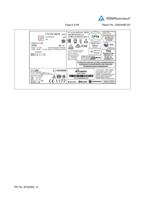
F.3.2.1 Manufacturer identification ................................ ... : See copy of marking plate P
F.3.2.2 Model identification ................................ ............... : See copy of marking plate P
F.3.3 Equipment rating markings P
F.3.3.1 Equipment with direct connectio n to mains P
F.3.3.2 Equipment without direct connection to mains N/A
F.3.3.3 Nature of the supply voltage ................................ .. : IEC 60417 - 5031 P
F.3.3.4 Rated voltage ................................ ........................ : See copy of marking plate P
F.3.3.5 Rated frequency ................................ .................... : N/A
Page 341 of 406

Page 30 of 88 Report No. : 60404490 001
IEC 62368 - 1
Clause Requirement + Test Result - Remark Verdict
TR F No. IEC62368_1 C
F.3.3.6 Rated current or rated power ................................ : See copy of marking plate P
F.3.3.7 Equipment with multiple supply connections N/A
F.3.4 Voltage setting device N/A
F.3.5 Terminals and operating devices N/A
F.3.5.1 Mains appliance outlet and socket - outlet markings
................................ ................................ ............... : No such component N/A
F.3.5.2 Switch position identification marking .................... : No such component N/A
F.3.5.3 Replacement fuse identification and rating
markings ................................ ................................ : No replaceable fuse N/A
Instructional safeguards for neutral fuse ............... : No such component N/A
F.3.5.4 Replacement battery identifi cation marking .......... : No replaceable battery N/A
F.3.5.5 Neutral conductor terminal N/A
F.3.5.6 Terminal marking location N/A
F.3.6 Equipment markings related to equipment
classification N/A
F.3.6.1 Class I equipment N/A
F.3.6.1.1 Protective earthing c onductor terminal .................. : N/A
F.3.6.1.2 Protective bonding conductor terminals ............... : N/A
F.3.6.2 Equipment class marking ................................ ...... : N/A
F.3.6.3 Functional earthing terminal marking .................... : N/A
F.3.7 Equipment IP rating marking ................................ . : N/A
F.3.8 External power supply output ma rking .................. : N/A
F.3.9 Durability, legibility and permanence of marking P
F.3.10 Test for permanence of markings P
F.4 Instructions
N/A
a) Information prior to installation and initial use It shall be evaluated in the
end - equipment N/A
b) Equipment fo r use in locations where children not
likely to be present N/A
c) Instructions for installation and interconnection N/A
d) Equipment intended for use only in restricted
access area N/A
e) Equipment intended to be fastened in place N/A
f) Instr uctions for audio equipment terminals N/A
g) Protective earthing used as a safeguard N/A
Page 342 of 406

Page 31 of 88 Report No. : 60404490 001
IEC 62368 - 1
Clause Requirement + Test Result - Remark Verdict
TR F No. IEC62368_1 C
h) Protective conductor current exceeding ES2 limits N/A
i) Graphic symbols used on equipment N/A
j) Permanently connected equipment not provided
with al l - pole mains switch N/A
k) Replaceable components or modules providing
safeguard function N/A
l) Equipment containing insulating liquid N/A
m ) Installation instructions for outdoor equipment N/A
F.5
Instructional safeguards N/A
G COMPONENTS
N/A
G.1 Switches
N/A
G.1.1 General No such switches are used as
disconnect devices N/A
G.1.2 Ratings, endurance, spacing, maximum load N/A
G.1.3 Test method and compliance N/A
G.2 Relays
N/A
G.2.1 Requirements No such relays are used as
disconnect de vices N/A
G.2.2 Overload test N/A
G.2.3 Relay controlling connectors supplying power to
other equipment N/A
G.2.4 Test method and compliance N/A
G.3 Protective devices
N/A
G.3.1 Thermal cut - offs No thermal cut - offs N/A
Thermal cut - outs separatel y approved according to
IEC 60730 with conditions indicated in a) & b) N/A
Thermal cut - outs tested as part of the equipment as
indicated in c) N/A
G.3.1.2 Test method and compliance N/A
G.3.2 Thermal links No thermal links N/A
G.3.2.1 a) Thermal l inks tested separately according to IEC
60691 with specifics N/A
b) Thermal links tested as part of the equipment N/A
G.3.2.2 Test method and compliance N/A
G.3.3 PTC thermistors No PTC thermistors N/A
G.3.4 Overcurrent protection devices N/A
Page 343 of 406

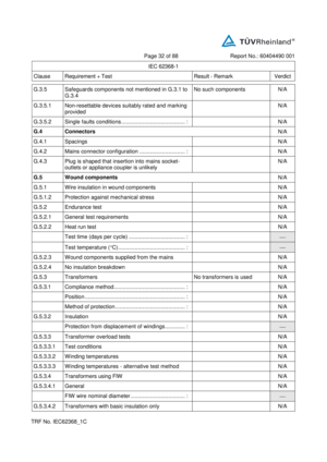
Page 32 of 88 Report No. : 60404490 001
IEC 62368 - 1
Clause Requirement + Test Result - Remark Verdict
TR F No. IEC62368_1 C
G. 3.5 Safeguards components not mentioned in G.3.1 to
G.3.4 No such components N/A
G.3.5.1 Non - resettable devices suitably rated and marking
provided N/A
G.3.5.2 Single faults conditions ................................ .......... : N/A
G.4 Connectors
N/A
G.4.1 Spacings N/A
G.4.2 Mains connect or configuration .............................. : N/A
G.4.3 Plug is shaped that insertion into mains socket -
outlets or appliance coupler is unlikely N/A
G.5 Wound components
N/A
G.5.1 Wire insulation in wound components N/A
G.5.1.2 Protection against mechanical stress N/A
G.5.2 Endurance test N/A
G.5.2.1 General test requirements N/A
G.5.2.2 Heat run test N/A
Test time (days per cycle) ................................ ..... :
Test temperature ( C) ................................ ............ :
G.5.2.3 Wound components supplied from the mains N/A
G.5.2.4 No insulation breakdown N/A
G.5.3 Tra nsformers No transformers is used N/A
G.5.3.1 Compliance method ................................ ............... : N/A
Position ................................ ................................ .. : N/A
Method of protection ................................ .............. : N/A
G.5.3.2 Insulation N/A
Protection from displacement of windings ............. :
G.5.3.3 Transformer overload tests N/A
G.5.3.3.1 Test condit ions N/A
G.5.3.3.2 Winding temperatures N/A
G.5.3.3.3 Winding temperatures - alternative test method N/A
G.5.3.4 Transformers using FIW N/A
G.5.3.4.1 General N/A
FIW wire nominal diameter ................................ .... :
G.5.3.4.2 Transformers with basic insulation only N/A
Page 344 of 406

Page 33 of 88 Report No. : 60404490 001
IEC 62368 - 1
Clause Requirement + Test Result - Remark Verdict
TR F No. IEC62368_1 C
G.5.3.4.3 Transformers with double insulation or reinforced
insulation ................................ ............................... : N/A
G.5.3.4.4 Transformers with FIW wound on metal or ferrite
core N/A
G.5.3.4.5 Thermal cycling test and compliance N/A
G.5.3.4.6 Partial discharge test N/A
G.5.3.4.7 Ro utine test N/A
G.5.4 Motors (See appended table 4.1.2) N/A
G.5.4.1 General requirements N/A
G.5.4.2 Motor overload test conditions N/A
G.5.4.3 Running overload test N/A
G.5.4.4.2 Locked - rotor overload test N/A
Test duration (days) ................................ .............. :
G.5.4.5 Running overload test for DC motors N/A
G.5.4.5.2 Tested in the unit N/A
G.5.4.5.3 Alternative method N/A
G.5.4.6 Locked - rotor overload test for DC motors N/A
G.5.4.6.2 Tested in the unit N/A
Maximum Temperature ................................ ........ : (See appended tab le B.3, B.4) N/A
G.5.4.6.3 Alternative method N/A
G.5.4.7 Motors with capacitors N/A
G.5.4.8 Three - phase motors N/A
G.5.4.9 Series motors N/A
Operating voltage ................................ ................. :
G.6 Wire Insulation
N/A
G.6.1 General N/A
G.6.2 Enamelled windin g wire insulation N/A
G.7 Mains supply cords
N/A
G.7.1 General requirements N/A
Type ................................ ................................ ....... :
G.7.2 Cross sectional area (mm 2
or AWG) ..................... : N/A
G.7.3 Cord anchorages and strain relief for non -
detachable power supply cords N/A
G.7.3.2 Cord strain relief N/A