Page 193 of 394

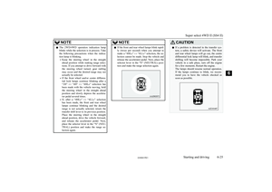
It will flash in case there is a malfunction in
the system. For details, refer to “SONAR
OFF indication lamp” on page 6-56.
To return the system to the operating state, push the “SONAR” switch again. When the
system returns to the operating state, the buz- zer sounds once and the “SONAR OFF” indi-
cation lamp turns off.
NOTEl The “SONAR OFF” indication lamp flashes
once when the ignition switch is turned to
the “ON” position.
The warning buzzer sounds when the system
detects an obstacle during operation.
NOTEl After pushing the “SONAR” switch, revers-
ing sensor system operation differs accord-ing to the detection area setting.
• Setting when towing bar is not equipped
When the selector lever is moved to the
“R” (REVERSE) position, the reversing sensor system will operate even if the cor-
ner sensor operation was stopped by push-
ing the “SONAR” switch.
• Setting when towing bar is equipped
When reversing sensor system operation was stopped by pushing the “SONAR”
switch, the reversing sensor system will not operate until the engine has been stop- ped even if the selector lever is moved to
the “R” (REVERSE) position.
To resume reversing sensor system opera- tion, push the “SONAR” switch or stop and restart the engine, and then move the
gearshift lever or selector lever to the “R” position.
Warning for obstacles
If there is an obstacle behind the vehicle, a
warning buzzer sounds to indicate the dis- tance between the vehicle and the obstacle.
Corner sensor
Vehicle to obstacle distanceWarning sound cy- cleApprox. 50 to 40 cmIntermittentVehicle to obstacledistanceWarning sound cy- cleApprox. 40 to 20 cmFast intermittentWithin approx.20 cmContinuous
Back sensor (vehicles without a towing
bar)
Vehicle to obstacle distanceWarning sound cy- cleApprox. 150 to80 cmIntermittentApprox. 80 to 40 cmFast intermittentWithin approx.40 cmContinuous
Back sensor (vehicles with a towing bar)
Vehicle to obstacle distanceWarning sound cy- cleApprox. 150 to120 cmIntermittentApprox. 120 to 60 cmFast intermittentWithin approx.60 cmContinuous
Reversing sensor system*
6-55OVWX17E1Starting and driving6
Page 194 of 394

CAUTIONlThe distances given are to be used for refer-
ence only, as errors may be caused by vari- ous factors, such as temperature, humidity,
or the shape of the obstacles.Changing the detection areas
E00615800032
The detection areas can be changed as fol-
lows:
Vehicles with a towing bar
While the operation of the system is stopped
at the “SONAR” switch, push the “SONAR”
switch approximately 3 seconds or more, and release it. The buzzer sounds twice to indi-
cate that the detection area has been changed.
Vehicles without a towing bar
While the operation of the system is stopped at the “SONAR” switch, push the “SONAR”
switch approximately 3 seconds or more, and
release it. The buzzer sounds once to indicate
that the detection area has been changed.
NOTEl The detection area will not change if you
keep the “SONAR” switch pushed for 10
seconds or more.“SONAR OFF” indication
lamp
E00615901362
In case there is a malfunction in the reversing
sensor system, the “SONAR OFF” indicationlamp will flash and the warning buzzer willsound for approximately 5 seconds. Even af-ter the buzzer has stopped sounding, the indi-
cation lamp will continue flashing until the
system reverts to the normal state. We rec- ommend you to have your vehicle inspection.
Rear-view camera*
E00618402277
The rear-view camera is a system that showsthe view behind the vehicle on a screen of the
MITSUBISHI Multi Communication System
(MMCS), the DISPLAY AUDIO or the
Smartphone Link Display Audio.
CAUTIONl The rear-view camera is an assistance sys-
tem that enables the driver to check for ob- stacles behind the vehicle. Its range of view
is limited, so you should not overly depend on it. Please drive just as carefully as you
would if the vehicle did not have the rear-
view camera.
l Be sure to visually confirm safety around the
vehicle with your own eyes. Do not depend entirely on the rear-view camera.
Range of view of rear-view
camera
The range of view of the rear-view camera is
limited to the area shown in the illustrations.
Because the camera is built in the overhang- ing area of the vehicle (spare wheel garnish),it cannot show the bottom of the spare wheel
garnish and the right behind the vehicle (rear bumper and backdoor).
When reversing, be sure to visually confirm
safety around the vehicle.
Rear-view camera*
6-56OVWX17E1Starting and driving6
Page 195 of 394

Location of rear-view camera
The rear-view camera (A) is integrated intothe spare wheel garnish.
Range of view of rear-viewcamera
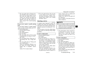
How to use the rear-view cam-
era
When you place the selector lever in the “R”
(REVERSE) position with the ignition switch in the “ON” position, the view behind the ve-
hicle will automatically appear on the screen of the MITSUBISHI Multi Communication
System (MMCS), the DISPLAY AUDIO or
the Smartphone Link Display Audio. When you move the selector lever to any other posi-tion, the screen will return to its original indi-
cation.
CAUTIONl The rear-view camera has a special lens that
can make objects shown on the screen ap-
pear to be closer or further away than they
actually are.CAUTIONl The line (red) shows the point approximately
50 cm behind the rear extremity of the rear
bumper.
Be careful because the spare wheel garnish overhangs for approximately 30 cm behind
the rear extremity of the rear bumper.NOTEl Because the rear-view camera has a special
lens, the lines on the ground between park-
ing spaces may not look parallel on the screen.
l In the following situations, the screen indi-
cation may be difficult to see. There is no abnormality.
• Low light (night time)
• When the light of the sun or the light from
a vehicle’s headlamps shines directly into
the lens
l If the camera is hot and is then cooled by
rain or a car wash, the lens can mist up. This
phenomenon does not indicate a malfunc- tion.
l It is not possible to fully see obstacles when
the lens is dirty. If the lens becomes conta- minated by water droplets, snow, mud or oil,
wipe off the contamination, taking care not to scratch the lens.
l Please observe the following cautions. Ig-
noring them could lead to a camera malfunc-
tion.
• Do not subject the camera to physical
shock.
Rear-view camera*
6-57OVWX17E1Starting and driving6
Page 196 of 394

NOTE•Do not apply wax to the camera.
• Do not splash the camera with boiling wa-
ter.
• Do not disassemble the camera.
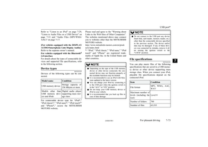
Reference lines on the screen
Reference lines and upper surface of the rear
bumper (A) are displayed on the screen.
l Red line (B) indicates approximately
50 cm behind the rear bumper.
l Two Green lines (C) indicate approxi-
mately 20 cm outside of the vehicle body.
l Short transverse lines (1 to 3) indicate
distance from the rear bumper.
Check surroundings for safety.
1- Approximately at the rear edge of the rear bumper
2- Approximately 100 cm
3- Approximately 200 cm
NOTEl When the vehicle is tilting because of the
number of people in the vehicle, the weight and positioning of luggage, and/or the condi-tion of the road surface, the lines in the view
from the rear-view camera may not be accu- rately positioned relative to the actual road.
l The reference lines for distance and vehicle
width are based on a level, flat road surface. In the following cases, objects shown on thescreen will appear to be farther off than they
actually are.
• When the rear of the vehicle is weighed
down with the weight of passengers and
luggage in the vehicle.
A- Actual objects
B- Objects shown on the screen
• When there is an upward slope at the
back.
NOTE
A- Actual objects
B- Objects shown on the screen
Rear-view camera*
6-58OVWX17E1Starting and driving6
Page 197 of 394

NOTElThe reference lines for distance and vehicle
width are intended to indicate the distance to
a flat object such as a level, flat road surface.
This may make the distance to a projecting object shown on the screen differ from the actual distance to the projecting object. Do
not use them as a guide for distances to solid objects.
Example: On the screen the point B appears
the nearest, then the point C and A in order of distance. The points A and B actually are the same distances from the vehicle, and the
point C is farther off than the points A and
B.Cargo loads
E00609901224
Cargo loads precautionsCAUTIONl When loading luggage, be careful to the fol-
lowing.
• Stow cargo and luggage in the luggage
compartment whenever possible.
• Distribute cargo or luggage evenly not to
be unbalanced in weight.
• Do not place cargo or luggage on the in-
strument panel.
Also, do not stack up cargo or luggage on the front passenger’s seat or the rear seats.
Having the driver’s vision blocked, and your cargo being thrown inside the cabin
if you suddenly have to brake can cause a
serious accident or injury.
Loading a roof carrier
CAUTIONl Use a roof carrier that properly fits your ve-
hicle.
Do not load luggage directly onto the roof.
For installation, refer to the instruction man-
ual accompanying the roof carrier.Roof carrier mounting brack-
ets*3-door models5-door models
When installing the roof carrier, use the brackets (A). The brackets (A) are located
under each roof drip moulding (B).
NOTEl We recommend you to use a genuine
MITSUBISHI roof carrier, since the brack-
ets to be used have a special shape. For de-
tails, we recommend you to consult a
MITSUBISHI MOTORS Authorized Serv-
ice Point.
Cargo loads
6-59OVWX17E1Starting and driving6 Check surroundings for safety
Page 198 of 394

Roof carrier precautionCAUTIONlMake sure that the weight of the luggage
does not exceed the allowable roof load.
If the allowable roof load is exceeded, this may cause damage to the vehicle.
The roof load is the total allowable load on
the roof (the weight of the roof carrier plus
the weight of luggage placed on the roof car- rier).
For specific figures, please refer to “Maxi-
mum roof load” on page 11-06 .
l When luggage is loaded onto the vehicle,
please make sure to drive slowly and avoid
excessive manoeuvres such as sudden brak- ing or quick turning.
In addition, place the luggage on the carrier
so that its weight is distributed evenly with the heaviest items on the bottom. Do not load items that are wider than the roof carri-
er.
The additional weight on the roof could raise
the vehicle’s centre of gravity and affect ve- hicle handling characteristics.
As a result, driving errors or emergency ma-
noeuvres could lead to a loss of control and
result in an accident.
l Before driving and after travelling a short
distance, always check the load to make sure it is securely fastened to the roof carrier.
Check periodically during your travel that
the load remains secure.NOTEl To prevent wind noise or reduction in fuel
economy, remove the roof carrier when not
in use.
l Before using an automatic car wash, remove
the roof carrier.
l Be sure that adequate clearance is main-
tained for raising the sunroof (if so equip-
ped) when installing a roof carrier.Trailer towing
E00610001850
In order to tow a trailer with your vehicle,
when having a trailer towing device mounted that meets all relevant regulations in your
area, consult a MITSUBISHI MOTORS Au-
thorized Service Point.
The regulations concerning the towing of a
trailer may differ from country to country. You are advised to obey the regulations in
each area.
CAUTIONl Danger of Accident!
A towing bar should be fitted according to MITSUBISHI MOTORS guidelines.
When you are going to tow a trailer, move
the transfer shift lever to “4H” position.
Selecting the “2H” drive may increase the differential oil temperature, resulting in pos-sible damage to the driving system.
Further, the drive train will be subjected to
excessive loading possibly leading to oil leakage, component seizure, or other serious faults.
Maximum towable weight with
brake and maximum trailer- nose weight
Never exceed the maximum towable weight
with brake and the maximum trailer-nose weight as listed in the specifications. (Referto “Vehicle weight” on page 11-06 .)
If you tow a trailer at an altitude of more than
1,000 m above sea-level, reduce your weight
by 10 % of the gross combination weight for
every increase of 1,000 m above sea-level, as the engine output is lowered owing to de-
crease in atmospheric pressure.
Trailer towing
6-60OVWX17E1Starting and driving6
Page 199 of 394
Towing bar mounting specifi-cations
See the following table for fixing points (A) for the towing bar.
Trailer towing
6-61OVWX17E1Starting and driving6
Page 200 of 394
Trailer towing
6-62OVWX17E1Starting and driving6