Page 145 of 394
Inside rear-view mirrorE00600801943
Adjust the rear-view mirror only after mak-
ing any seat adjustments so you have a clear
view to the rear of the vehicle.WARNINGl Do not attempt to adjust the rear-view
mirror while driving. This can be danger-
ous.
Always adjust the mirror before driving.
Adjust the rear-view mirror to maximize the
view through the rear window.
To adjust the vertical mirror
position
It is possible to move the mirror up and down
to adjust its position.
To adjust the mirror position
It is possible to move the mirror up/down and left/right to adjust its position.
To reduce the glare
Type 1
The lever (A) at the bottom of the mirror can
be used to adjust the mirror to reduce the
glare from the headlamps of vehicles behind you during night driving.
1- Normal
2- Anti-glare
Inside rear-view mirror
6-07OVWX17E1Starting and driving6Type 2
Type 1
Page 146 of 394

Type 2
When the headlamps of the vehicles behind
you are very bright, the reflection factor of the rear-view mirror is automatically changed
to reduce the glare.
When the ignition switch is turned to the
“ON” position, the reflection factor of the mirror is automatically changed.
NOTEl Do not hang items on, or spray glass cleaner
on the sensor (1), as reduced sensitivitycould result.Outside rear-view mirrors
E00600900484
Compound curved-surface mirror*
On the driver’s side, a compound curved-sur-
face mirror is used, while on the front passen-
ger’s side, a single curved-surface mirror is used.
1- Compound curved-surface mirror
2- Single curved-surface mirror
While the single curved-surface mirror has a fixed curvature, the compound curved-sur- face mirror has different curvatures between
the inner and outer sides of the boundary line
(A).
The inner side of the boundary line provides
the same vision as that available from an or- dinary door mirror.
However, the outer side of the boundary line
provides a wider angle of vision compared to an ordinary door mirror.WARNINGl The sense of distance that you get from an
object you see on the inner side of themirror boundary line differs from the
sense of distance that you get from an ob-
ject you see on the outer side.
An object you see on the outer side of the boundary line of the mirror will look far-
ther away than actually is as compared
with an object you see on the inner side.To adjust the mirror position
E00601000105
The outside rear-view mirrors can be operat-
ed when the ignition switch is in the “ON” or “ACC” position.
WARNINGl Do not attempt to adjust the rear-view
mirrors while driving. This can be dan-
gerous.
Always adjust the mirrors before driving.
Outside rear-view mirrors
6-08OVWX17E1Starting and driving6
Page 147 of 394

WARNINGlYour vehicle is equipped with convex type
mirrors. Please take into consideration,that objects you see in the mirror will looksmaller and farther away compared to a normal flat mirror.
Do not use this mirror to estimate dis- tance of following vehicles when changing
lanes.
1. Place the lever (A) to the same side as
the mirror whose adjustment is desired.
L- Left outside mirror adjustment
R- Right outside mirror adjustment
2. Press the switch (B) to the left, right, up
or down to adjust the mirror position. 1- Up
2- Down
3- Right
4- Left
3. Return the lever (A) back to the middle
position (•).Retracting and extending the
outside mirrors
E00618200011
The outside mirrors can be folded in towards the side window to prevent damage whenparking in narrow areas.
CAUTIONl Do not drive the vehicle with the mirror fol-
ded in. The lack of rearward visibility nor-mally provided the mirror could lead to an
accident.
Retracting and extending the
mirrors using the mirror re- tractor switch
With the ignition switch in the “ON” or
“ACC” position, push the mirror retractor switch to retract the mirrors. Push it again to
extend the mirrors to their original positions.
After placing the ignition switch in the “LOCK” position, it is possible to retract and
extend the mirrors using the mirror retractor switch for about 30 seconds.CAUTIONl It is possible to retract and extend the mir-
rors by hand. After retracting a mirror using
the mirror retractor switch, however, you should extend it by using the switch again,
not by hand. If you extended the mirror by
hand after retracting it using the switch, it would not properly lock in position. As a re-
sult, it could move because of the wind or
vibration while you are driving, taking away your rearward visibility.
Outside rear-view mirrors
6-09OVWX17E1Starting and driving6
Page 148 of 394

NOTElBe careful not to get your hands trapped
while a mirror is moving.
l If you move a mirror by hand or it moves af-
ter hitting a person or object, you may not be
able to return it to its original position using the mirror retractor switch. If this happens,
push the mirror retractor switch to place the mirror in its retracted position and then push
the switch again to return the mirror to its original position.
l If the battery voltage is low and you start the
engine while extending the mirrors, the mir- rors may stop part-way. If this happens, push
the mirror retractor switch to retract the mir- rors and then push the switch again to extend
them.
l When freezing has occurred and mirrors fail
to operate as intended, please refrain from
repeated pushing of the retractor switch as
this action can result in burn-out of the mir- ror motor circuits.
Automatic extension of mirrors
If the engine is stopped and started with the
mirrors retracted, the mirrors automatically
extend for safety when the vehicle speed rea-
ches 30 km/h (19 mph).
Heated mirror*
E00601200312
To demist or defrost the outside rear-view
mirrors, press the rear window demister
switch.
The indication lamp (C) will illuminate while
the demister is on.
The heater will be turned off automatically in about 20 minutes.Ignition switch
E00601403399LOCK
The engine is stopped and the steering wheel
locked. The key can only be inserted and re- moved in this position.
ACC
The engine is stopped, but the electrical devi-
ces such as the radio and cigarette lighter can be operated.
ON
The engine is running, and all the vehicle’s
electrical devices can be operated.
START
The starter motor operates. After the engine has started, release the key and it will auto- matically return to the “ON” position.
NOTEl Your vehicle is equipped with an electronic
immobilizer. To start the engine, the ID codetransmitted by the transponder inside the key must match the code registered in the immo-bilizer computer.
Refer to “Electronic immobilizer” on page
3-03.
Ignition switch
6-10OVWX17E1Starting and driving6
Page 149 of 394

Ignition switch illumination
In the situations listed below, the ignitionswitch illumination comes on to facilitate in-
sertion or removal of the ignition key.
l When any door or the backdoor is
opened, the ignition switch illumination
comes on. When it is closed, the ignition switch illumination becomes steadily
dimmer until completely going off about 15 seconds later.
l When the ignition key is removed with
all the doors and the backdoor closed, the ignition switch illumination comes
on and stays on for about 15 seconds.
The ignition switch illumination immediately goes off if any of the following actions is tak-
en while it is on.
l All of the doors and the backdoor are
closed, and the ignition switch is turned
to the “ON” position.
l All of the doors and the backdoor are
locked using the central door lock func-
tion.
l All of the doors and the backdoor are
locked using the keyless entry system (if so equipped).
NOTEl If the interior lamp switch is in the “()”
position, the ignition switch illumination
will not come on.
l It is possible to adjust the period of ignition
switch illumination (the period until the igni-
tion switch illumination goes off). For de-
tails, we recommend you to consult a
MITSUBISHI MOTORS Authorized Serv-
ice Point.
l If the illumination period of the room & map
lamps or rear personal lamps (the period un-
til these lamps go off) is adjusted, the period
of ignition switch illumination (the period until the ignition switch illumination goes
off) will automatically be changed at the same time.
If the illumination period of the room & map
lamps or rear personal lamps is set to zero
(in other words, the illumination keep-on function is deactivated), the ignition switch
illumination will not come on when the igni-
tion switch is removed.
For information, we recommend you to con-
sult a MITSUBISHI MOTORS Authorized
Service Point.To remove the key
When removing the key, first set the selector
lever to the “P” (PARK) position, and thenturn the key to the “LOCK” position and re-
move it.
CAUTIONl If the engine is stopped while driving, the
brake servomechanism will cease to function and braking efficiency will deteriorate. Also,
the power steering system will not function
and it will require greater manual effort to
operate the steering.
l Do not leave the key in the “ON” position
for a long time when the engine is not run- ning, doing so will cause the battery to bedischarged.
l Do not turn the key to the “START” position
when the engine is running, doing so could damage the starter motor.
Ignition switch
6-11OVWX17E1Starting and driving6
Page 150 of 394

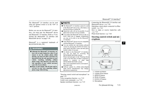
Steering wheel lockE00601500298
To lock
Remove the key at the “LOCK” position.
Turn the steering wheel until it is locked.
To unlock
Turn the key to the “ACC” position while
moving the steering wheel slightly right and left.
CAUTIONl Remove the key when leaving the vehicle.
In some countries, it is prohibited to leave the key in the vehicle when parked.Starting
E00601600811
Tips for starting
l Do not operate the starter motor continu-
ously longer than 10 seconds; doing so
could run down the battery. If the engine
does not start, turn the ignition key back to “LOCK” position, wait a few seconds,and then try again. Trying repeatedly with the starter motor still turning will
damage the starter mechanism.
WARNINGl Never run the engine in a closed or poorly
ventilated area any longer than is needed to move your vehicle in or out of the area.Carbon monoxide gases are odourless and
can be fatal.CAUTIONl Never attempt to start the engine by pushing
or pulling the vehicle.
l Do not run the engine at high rpm or drive
the vehicle at high speed until the engine has had a chance to warm up.
l Release the ignition key as soon as the en-
gine starts to avoid damaging the starter mo-
tor.CAUTIONl If your vehicle is equipped with a turbo-
charger, do not stop the engine immediately
after high-speed or uphill driving. First al-
low the engine to idle to give the turbocharg-
er a chance to cool down.Starting the engine (petrol-
powered vehicles)
E00601703682
The starting procedure is as follows: 1. Insert the ignition key and fasten the seat
belt.
2. Make sure the parking brake is applied.
3. Depress and hold the brake pedal.
4. Make sure the selector lever is in the “P”
(PARK) position.
Steering wheel lock
6-12OVWX17E1Starting and driving6
Page 151 of 394

5.After turning the ignition key to the
“ON” position, make certain that all
warning lamps are functioning properly before starting the engine.
6. Turn the ignition key to the “START”
position without depressing the accelera-
tor pedal, and release it when the engine starts.NOTEl A ticking noise may be heard after starting
the engine. This is not an abnormal condi-tion. The noise will disappear after a shorttime of engine running.
If the ticking noise continues after the en-
gine is warmed up, we recommend you to have your vehicle checked.
When it is difficult to start the
engine
After several attempts, you may experience that the engine still does not start. 1. Make sure that all electric devices, such
as lamps, air conditioning blower and
rear window demister, are turned off.
2. While depressing the brake pedal, press
the accelerator pedal halfway and hold it
there, then crank the engine. Release the
accelerator pedal, immediately after the
engine starts.
3. If the engine still will not start, the en-
gine could be flooded with too much
petrol. While depressing the brake pedal, push the accelerator pedal all the way
down and hold it there, then crank the
engine for 5 to 6 seconds. Return the ig- nition switch to the “LOCK” position
and release the accelerator pedal. Wait a few seconds, and then crank the engine
again for 5 to 6 seconds while depress-
ing the brake pedal, but do not push the accelerator pedal. Release the ignition
key if the engine starts. If the engine
fails to start, repeat these procedures. If the engine still will not start, we recom-
mend you to have the vehicle checked.
Using the MIVEC engine
The MIVEC engine automatically switches its intake-valve control between a low-speed mode and a high-speed mode in accordancewith the driving conditions for maximum en-
gine performance.
NOTEl To protect the engine, the high-speed mode
may not be selected while the engine coolanttemperature is low. In such a case, the en-
gine revolutions do not rise to over
5,000 rpm even if the accelerator pedal is depressed.Starting the engine (diesel-
powered vehicles)
E00601801331
1. Insert the ignition key and fasten the seat
belt.
2. Make sure the parking brake is applied.
3. Depress and hold the brake pedal.
4. Make sure the selector lever is in the “P”
(PARK) position.
5. Turn the ignition key to the “ON” posi-
tion.
The diesel preheat indication lamp will
first illuminate, and then after a short
time go out, indicating that preheating is completed.
NOTEl If the engine is cold, the diesel preheat indi-
cation lamp is on for a longer time.
Starting
6-13OVWX17E1Starting and driving6
Page 152 of 394

NOTElWhen the engine has not been started within
about 5 seconds after the diesel preheat indi-
cation lamp went out, return the ignition key to the “LOCK” position. Then, turn the key
to the “ON” position to preheat the engine
again.
l When the engine is warm, the diesel preheat
indication lamp does not come on even if the
ignition key is placed in the “ON” position. Start the engine by turning the ignition key
right to the “START” position.
6. Turn the ignition key to the “START”
position without depressing the accelera- tor pedal, and release it when the engine
starts.
Fuel injection amount learning
process (diesel-powered vehi-cles)
E00616000044
To keep exhaust emissions and engine noise low, the engine very occasionally performs a
learning process for the fuel injection
amount.
The engine sounds slightly different from
usual while the learning process is taking place. The change in the engine sound does
not indicate a fault.
NOx trap catalyst
(dieselpowered vehicles)* E00649200020
A NOx (nitrogen oxide) trap catalyst absorbs
the NOx contained in the exhaust gas of the diesel engine.
To maintain the NOx absorbing function, the
fuel is supplied regularly to the catalyst while
driving, and the catalyst reduces NOx to harmless N2 (nitrogen).
The bar graph of momentary fuel consump-
tion in the centre information display and en- gine sound change while NOx is being
purged automatically by the catalyst. These
do not indicate a fault.Diesel particulate filter
(DPF)* E00619801460
The diesel particulate filter (DPF) is a devicethat captures most of the particulate matter
(PM) in the exhaust emissions of the diesel
engine. The DPF automatically burns away trapped PM during vehicle operation. Under
certain driving conditions, however, the DPF is not able to burn away all of the trapped PM
and, as a result, an excessive amount of PM accumulates inside it.
WARNINGl The DPF reaches very high temperatures.
Do not park your vehicle in areas where
combustible materials such as dry grass
or leaves can come in contact with a hot exhaust system since a fire could occur.CAUTIONl Do not use any type of fuel or engine oil that
is not specified for your vehicle. Also, do not use any moisture-removing agent or oth-
er fuel additive. Such substances could have a detrimental effect on the DPF.
Refer to “Fuel selection” on page 2-02 and
“Engine oil” on page 10-04.NOTEl To minimize the likelihood of excessive ac-
cumulation of PM, try to avoid driving for long periods at low speeds and repeatedly
driving short distances, and try to keep high
engine speed driving as much as possible.
NOx trap catalyst (dieselpowered vehicles)*
6-14OVWX17E1Starting and driving6