Page 329 of 394

CAUTIONlDo not bring nearby parts, plastic parts and
so on into contact with sulphuric acid (bat-
tery electrolyte) which may crack, stain or discolour them.
If they are in contact, wipe off with soft
cloth, chamois or the like and an aqueous solution of neutral detergent then immedi-
ately rinse the affected parts with plenty of
water.NOTEl Keep the terminals clean. After the battery is
connected, apply terminal protection grease.
To clean the terminals, use lukewarm water.
l Check to see if the battery is securely instal-
led and cannot be moved during travel. Also check each terminal for tightness.
l When the vehicle is to be left unused for a
long period of time, remove the battery and
store it in a place where the battery fluid will not freeze. The battery should be stored only in a fully charged condition.Tyres
E01001300239WARNINGlDriving with tyres that are worn, dam-
aged or improperly inflated can lead to a
loss of control or blow out of the tyres which can result in a collision with serious
or fatal injury.Tyre inflation pressures
E01001404254
Except for vehicles for Russia, Kazakhstan, Belarus and UkraineTyre sizeUp to 5 passengersUp to max. loadAt trailer towingFrontRearFrontRearFrontRear265/65R17 112H2.2 bar (220 kPa)2.4 bar (240 kPa)2.4 bar (240 kPa)2.8 bar (280 kPa)2.6 bar (260 kPa)3.0 bar (300 kPa)265/65R17 112S2.4 bar (240 kPa)2.6 bar (260 kPa)2.6 bar (260 kPa)3.0 bar (300 kPa)2.6 bar (260 kPa)3.0 bar (300 kPa)265/60R18 110H2.2 bar (220 kPa)2.4 bar (240 kPa)2.4 bar (240 kPa)2.8 bar (280 kPa)2.6 bar (260 kPa)
3.2 bar (320 kPa) *3.0 bar (300 kPa)
3.5 bar (350 kPa) **
: 5 door models
Tyres
10-11OVWX17E1Maintenance10
Page 330 of 394

Vehicles for Russia, Kazakhstan, Belarus and UkraineTyre sizeUp to 5 passengersUp to max. loadAt trailer towingFrontRearFrontRearFrontRear265/65R17 112H2.0 bar (200 kPa) *
2.2 bar (220 kPa)2.2 bar (220 kPa) *
2.4 bar (240 kPa)2.4 bar (240 kPa)2.8 bar (280 kPa)2.6 bar (260 kPa)3.0 bar (300 kPa)265/60R18 110H2.0 bar (200 kPa) *
2.2 bar (220 kPa)2.2 bar (220 kPa) *
2.4 bar (240 kPa)2.4 bar (240 kPa)2.8 bar (280 kPa)2.6 bar (260 kPa)3.0 bar (300 kPa)* : Vehicles for 3000 models
Check the tyre inflation pressure of all the tyres while they are cold; if insufficient or excessive, adjust to the specified value.
After the tyre inflation pressure has been adjusted, check the tyres for damage and air leaks. Be sure to put caps on the valves.
Wheel condition
E01001800478
1- Location of the tread wear indicator
2- Tread wear indicator
Check the tyres for cuts, cracks and other
damage. Replace the tyres if there are deep
cuts or cracks. Also check each tyre for pieces of metal or pebbles.
The use of worn tyres can be very dangerous
because of the greater chance of skidding or
hydroplaning. The tread depth of the tyres
must exceed 1.6 mm in order for the tyres to meet the minimum requirement for use.
Tread wear indicators will appear on the sur-
face of the tyre as the tyre wears, thereby in-
dicating that the tyre no longer meets the
minimum requirement for use. When these
wear indicators appear, the tyres must be re-
placed with new ones.
When replacement of any of the tyres is nec- essary, replace all of them.CAUTIONl Always use tyres of the same size, same
type, and same brand, and which have no wear differences.
Using tyres of different size, type, brands or
degree of wear, will increase the differential
oil temperature, resulting in possible damage to the driving system. Further, the drive train
will be subjected to excessive loading, possi- bly leading to oil leakage, component seiz-ure, or other serious faults.
Tyres
10-12OVWX17E1Maintenance10
Page 331 of 394

Replacing tyres and wheels
E01007201530
CAUTIONlAvoid using different size tyres from the one
listed and the combined use of different
types of tyres, as this can affect driving safe- ty.
Refer to “Tyres and wheels” on page
11-11.
l Even if a wheel has the same rim size and
offset as the specified type of wheel, its
shape may prevent it from being fitted cor- rectly. We recommend you to consult a spe-
cialist before using wheels that you have.
l If your vehicle is equipped with a tyre pres-
sure monitoring system, only MITSUBISHI
MOTORS genuine wheels should be used.
Use of another type of wheel risks air leaks and sensor damage, as it will not be possible
to install the tyre pressure sensor properly.
Refer to “Tyre pressure monitoring system
(TPMS)” on page 6-48.
Wheel balance
On vehicles equipped with 17x7 1/2J size
aluminium wheels (round rim type), if you
need to balance a wheel, put the balance weight (A) on the specified position which is
spoke side from the notch (B) on the inner surface of the wheel.
There is a possibility that the balance weight
is interfered the related brake part if it is put
any place other than the specified position.
For details, we recommend you to consult a MITSUBISHI MOTORS Authorized Service
Point.Tyre rotation
E01001901203
Tyre wear varies with vehicle conditions,
road surface conditions and individual driv- er’s driving habits. To equalize the wear andhelp extend tyre life, it is recommended to ro-
tate the tyres immediately after discovery of
abnormal wear, or whenever the wear differ- ence between the front and rear tyres is rec-
ognizable.
When rotating tyres, check for uneven wear
and damage. Abnormal wear is usually caused by incorrect tyre pressure, improper wheel alignment, out of balance wheel, or se-
vere braking. We recommend you to have it checked to determine the cause of irregular
tread wear.Spare tyre used*Spare tyre not usedTyres that have arrows showing rotation directionFrontFrontFront
Tyres
10-13OVWX17E1Maintenance10
Page 332 of 394

*- If the spare tyre wheel differs from thestandard tyre wheel, do not perform tyre rota-
tion using a spare wheel.CAUTIONl If the tyres have arrows (A) indicating the
correct direction of rotation, swap the front and rear wheels on the left hand side of the
vehicle and the front and rear wheels on the
right hand side of the vehicle separately. Keep each tyre on its original side of the ve-hicle. When fitting the tyres, make sure the
arrows point in the direction in which the wheels will turn when the vehicle moves
forward. Any tyre whose arrow points in the
wrong direction will not perform to its full potential.Front
CAUTIONl Avoid the combined use of different types of
tyres.
Using different types of tyres can affect ve-
hicle performance and safety.Snow tyres
E01002001894
The use of snow tyres is recommended for
driving on snow and ice. To preserve driving stability, mount snow tyres of the same size and tread pattern on all 4 wheels.
Snow tyres worn more than 50% are no lon-
ger suitable for use as snow tyres.
Snow tyres which do not meet specifications must not be used.
CAUTIONl Observe permissible maximum speed for
your snow tyres and the legal speed limit.
l If your vehicle is equipped with a tyre pres-
sure monitoring system, only MITSUBISHI
MOTORS genuine wheels should be used.
Use of another type of wheel risks air leaks and sensor damage, as it will not be possible
to install the tyre pressure sensor properly.
Refer to “Tyre pressure monitoring system
(TPMS)” on page 6-48.NOTEl The laws and regulations concerning snow
tyres (driving speed, required use, type, etc.)
vary. Find out and follow the laws and regu- lations in the area you intend to drive.
l If flange nuts are used on your vehicle,
change to tapered nuts when steel wheels are used.Tyre chains
E01002101794
On 4WD vehicles in which the driving power
is distributed preferentially to the rear wheels, ensure that the tyre chains are fitted
on the rear in accordance with the manufac- turer’s instructions.
Use only tyre chains which are designed for use with the tyres mounted on the vehicle: use of the incorrect size or type of chain
could result in damage to the vehicle body.
Before fitting tyre chains, we recommend you to consult a MITSUBISHI MOTORS
Authorized Service Point. The max. chain
height is as follows.
Tyre sizeWheel size
Max. chain
height[mm]265/65R17 112H
265/65R17 112S
17 x 7 1/2 J22Tyres
10-14OVWX17E1Maintenance10
Page 333 of 394
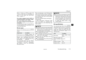
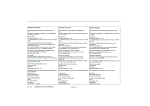
![MITSUBISHI SHOGUN 2017 Owners Manual (in English) Tyre sizeWheel size
Max. chainheight[mm]265/60R18 110H18 x 7 1/2 J
The speed limit for tyre chain is 50 km/h(30 mph) and remove the tyre chains as soon as possible on snow free roads.
MITSUBISHI SHOGUN 2017 Owners Manual (in English) Tyre sizeWheel size
Max. chainheight[mm]265/60R18 110H18 x 7 1/2 J
The speed limit for tyre chain is 50 km/h(30 mph) and remove the tyre chains as soon as possible on snow free roads.](/manual-img/19/34886/w960_34886-332.png)
Tyre sizeWheel size
Max. chainheight[mm]265/60R18 110H18 x 7 1/2 J
The speed limit for tyre chain is 50 km/h(30 mph) and remove the tyre chains as soon as possible on snow free roads.
CAUTIONl As your vehicle is equipped with anti-lock
brake system (ABS), in order to ensure that the anti-lock brake system (ABS) will oper- ate correctly in situations where tyre chains
have been fitted, drive in “4H”, “4HLc” or “4LLc”.
l Practice fitting the chains before you need
them.
Don’t expect help from other people in the
cold.
l Choose a clear straight stretch of road where
you can pull over and still be seen while you are fitting the chains.
l Do not fit chains before you need them. This
will wear out your tyres and the road sur-
face.
l After driving around 100-300 metres, stop
and retighten the chains.
l Drive carefully and do not exceed 50 km/h
(30 mph). Remember, fitting chains is notgoing to stop accidents from happening.
l When tyre chains are installed, take care that
they do not damage the disc wheel or body.CAUTIONl An aluminium wheel can be damaged by a
tyre chain while driving. When fitting a tyre
chain on an aluminium wheel, take care that any part of the chain and fitting cannot be
brought into contact with the wheel.
l When installing or removing the tyre chains,
take care that hands and other parts of your
body are not injured by the sharp edges of
the vehicle body.NOTEl The laws and regulations concerning the use
of tyre chains vary. Always follow local laws and regulations.
In most countries, it is prohibited by law to
use tyre chains on roads without snow.Parking brake break-in
E01008300010
Break-in the parking brake linings whenever
the brake performance of the parking brake is insufficient or whenever the parking brake
linings and/or discs are replaced, in order to
assure the best brake performance.
This procedure is described in the vehicle service manual and can be carried out by a
MITSUBISHI MOTORS Authorized Service
Point.
Wiper blade rubber
replacement E01008200208
1. Lift the wiper arm off the windscreen. 2. Pull the wiper blade until its stopper (A)
disengages from the hook (B). Then, pull the wiper blade further to remove it.NOTEl Do not allow the wiper arm to fall onto the
windscreen; it could damage the glass.
3. Attach the retainers (C) to a new wiper
blade.
Parking brake break-in
10-15OVWX17E1Maintenance10
Page 334 of 394
Refer to the illustration to ensure that the
retainers are correctly aligned as you at-
tach them.
4. Insert the wiper blade into the arm, start-
ing with the opposite end of the blade from the stopper. Make sure the hook(B) is fitted correctly in the grooves in
the blade.
NOTEl If retainers are not supplied with the new
wiper blade, use the retainers from the old
blade.5. Push the wiper blade until the hook (B)
engages securely with the stopper (A).
Rear window wiper blade
1. Lift the wiper arm off the window glass.
2. Pull the wiper blade downward to disen-
gage it from the stopper (A) at the end of
the wiper arm. Pull the wiper blade fur-
ther to remove it.
3. Slide a new wiper blade through the
hook (B) on the wiper arm.NOTEl Do not allow the wiper arm to fall onto the
window glass; it could damage the glass.
4. Firmly insert the retainer (C) into the
groove (D) in the wiper blade.
Wiper blade rubber replacement
10-16OVWX17E1Maintenance10
Page 335 of 394

Refer to the illustration to ensure that the
retainers are correctly aligned as you in- sert them into the groove.NOTEl If a retainer is not supplied with the new
wiper blade, use the retainer from the old
blade.General maintenance
E01002700360
Fuel, engine coolant, oil and ex- haust gas leakage
Look under the body of your vehicle to check
for fuel, engine coolant, oil and exhaust gas
leaks.
WARNINGl If you see a suspicious fuel leak or if you
smell fuel, do not operate the vehicle; we recommend you to call for assistance.
Exterior and interior lamp op-
eration
Operate the combination lamp switch to
check that all lamps are functioning properly.
If the lamps do not illuminate, the probable cause is a blown fuse or defective lamp bulb.
Check the fuses first. If there is no blown
fuses, check the lamp bulbs.
For information regarding the inspection and
replacement of the fuses and the lamp bulbs, refer to “Fuses” on page 10-18 and “Re-
placement of lamp bulbs” on page 10-23.
If the fuses and bulbs are all OK, we recom- mend you to have your vehicle checked and
repaired.
Meter, gauge and indicator/
warning lamps operation
Run the engine to check the operation of all meters, gauges, and indicator/warning lamps.
If there is anything wrong, we recommend you to have your vehicle inspected.
Hinges and latches lubrication
Check all latches and hinges, and, if necessa- ry, have them lubricated.
For cold and snowy weather
E01002800299
Ventilation slots
The ventilation slots in front of the wind-
screen should be kept clear of leaves or brushed clear after heavy snowfall, so that
the operation of the heating and ventilation
systems will not be impaired.
Weatherstripping
To prevent freezing of the weatherstripping
on the doors, bonnet, etc., they should be treated with silicone grease.
General maintenance
10-17OVWX17E1Maintenance10
Page 336 of 394

Additional equipment
It is a good idea to carry a shovel or a short-handled spade in the vehicle during the win-ter so that you can clear away snow if you get
stranded. A small hand-brush for sweeping snow off the vehicle and a plastic scraper for
the windscreen and rear window are also use- ful.
Fusible links
E01002900434
The fusible links will melt to prevent a fire if
a large current attempts to flow through cer- tain electrical systems.
In case of a melted fusible link, we recom- mend you to have your vehicle inspected.For the fusible links, please refer to “Fuse
load capacity” on page 10-18.
WARNINGl Fusible links must not be replaced by any
other device. Failing to fit the correct fusi- ble link may result in fire in the vehicle,
property destruction and serious or fatal injuries at any time.Fuses
E01003000849Fuse block location
E01007601521
To prevent damage to the electrical systemdue to short-circuiting or overloading, each individual circuit is provided with a fuse.
There are fuse blocks in the passenger com- partment and in the engine compartment.
Passenger compartment
The fuse block in the passenger compartment is located in front of the driver’s seat at the position shown in the illustration.
Engine compartment
In the engine compartment, the fuse blocks
are located as shown in the illustration.
Type AType BFuse load capacity
E01007700105
The fuse capacity and the name of the electri- cal systems protected by the fuses are indica-
ted on the inside of the lid located at the driv-
er’s leg area and on the inside of the fuse block cover for fuses located in the engine
compartment.
Fusible links
10-18OVWX17E1Maintenance10