Page 233 of 264
 ..,.,
N ..,., ,....,
Tires with unidirectional tread design
Tires with unidirectional tread design must be
mounted with their tread pattern pointed in the
rig")
M N
i? co ,...., \!) ..,.,
N ..,., ,....,
Tires with unidirectional tread design
Tires with unidirectional tread design must be
mounted with their tread pattern pointed in the
right dir ection .
Using a spare tire with a tread pattern
intended for use in a specific direction
When us ing a spa re tire w ith a t read pa tte rn in
t e nded fo r use in a specific d ir e ct ion, p lease no te
the following:
- The direction of rotation is marked by an
arrow
on the side of the tire .
-If the spare t ire has to be installed in the incor
rect direction, use the spare tire only tempora
rily since the tire will not be able to achieve i ts
o ptimum performanc e character istics wit h re
gard to aquaplaning, noise and wea r.
- We recommend that you pay pa rticular atten
t io n t o this fact du ring wet weat he r and t hat
yo u adju st yo ur sp eed to match road condi
t ions.
- Re place the fla t tire w ith a new one and have i t
i nsta lled on yo ur vehicle as s oon as po ssible to
re store the han dling a dvan tages o f a un idirec
t io na l tire.
Notes on wheel changing
P lease read the information ¢ page 212, New
tires or wheels
i f you are going to use a spare tire
which is different from the tires on your ve hicle.
Afte r you change a tire:
- Check the tire pressure on the spare immedi
ately after installation.
- Have the wheel bolt tightening torque
checked with a torque wrench as soon as po s
sible by your authorized Audi dealer or quali
fied workshop .
- With steel and alloy wheel rims , the wheel
bolts are correctly tightened at a torque of 90
ft lbs. (120 Nm ).
- If you notice th at the wheel bolt s are corroded
and difficult to turn while changing a tire ,
they should be replaced before you check the
tightening torque .
Emergency assistance
-Replace the flat tire with a new one and have
it installed on your vehicle as soon as possi
ble. Remount the wheel cover .
Until then , drive with extra care and at reduced
speed s.
_& WARNING
- If you are going to e quip your ve hicl e wit h
tires o r rims which differ from those which
were factory installed, then be sure to read
the information ¢
page 212, New tires or
wheels.
- Always make sure the damaged wheel o r
even a flat tire a nd the jack a nd too l kit a re
p roperly secu red in the luggage compart
men t and are not loos e in t he passeng er
compa rt m ent.
- In an acci dent or sudde n man euver they
could fly forwa rd, inj uring a nyone in t he ve
h icle.
- Always s to re damag ed wh eel , jack and tools
s ecure ly in the luggage co mpart ment. Ot h
e rwi se, in an accident o r sud den man euver
they co uld fly forward, causing injury to pas
sen gers in t he ve hicle.
(D Note
D o not use co mmercially ava ilab le tire seal
a nts. O therwise, the e le ct ric al c ompone nts of
the tire pre ssure monit oring sys tem * w ill no
l on ger wor k properly and t he sensor for the
tire pressu re monito ring system * wi ll have to
b e replaced by qu alified workshop.
-
231
Page 234 of 264

Fuses and bulbs
Fuses and bulbs
Fuses
Replacing a fuse
A fuse that hast blown will have metal strips
that have burned through .
Fig. 18 2 Left cockpit: fuse panel cover
The fuses a re located at the fron t left and right of
the cockpit and behind the trim on the right side
of the luggage compartment.
• Swi tc h the ignition and all e lectr ica l equipment
off .
• Check the following table to see which fuse be
longs to the equipment.
• Remove the appropriate cover.
• Remove the colored p lastic clip from the fuse
panel, if necessary ¢
page 232, fig. 183. You
can d ispose of the p lastic clip .
• Remove the clamp from the rear side of the
cover ¢fig.182.
• Remove the fuse using the clamp.
• Rep lace the blow n fuse o nly w it h an ident ica l
new one.
• Install the cover .
Fuse color identification
Color Current
in amps
Black 1
Purp le 3
Light brown s
Brown 7.5
R ed 10
B lue 15
Yellow 20
White or transparent 25
232
Color Current in amps
Green 30
Orange 40
A WARNING
D o not repa ir fuses and never rep lace a blown
f u se wit h one that has a higher amp rating .
This can cause damage to the e lectr ica l sys
tem and a fire.
(D Note
I f a new fuse burns out again after short ly
h ave you have insta lled it, have the electrical
system checked by your author ized Audi deal
er.
(D Tips
- The followi ng table does not list fuse loca
t ions that a re not used.
- Some of the equipment items listed are op
t ional or only available on certain model
con figurations.
Left cockpit fuse assignment
F ig . 18 3 Le ft cockpi t: fuse panel wi th plastic clip
Page 235 of 264

No. Consumer
1 Dynamic steering
2 Electron ic Stabilization Control (module)
A/C system pressure sensor, electrome-
chanical")
M N
0 loo
rl I.O
"' N
"' rl
Fu se pa nel @ (black )
No. Consumer
1 Dynamic steering
2 Electron ic Stabilization Control (module)
A/C system pressure sensor, electrome-
chanical parking brake, HomeLink, auto-
3 mat
ic dimming interior rear view mirror,
air quality/outside air sensor, Electron ic
Stabilization Control (button)
s Sound actuator
6 Headlight range control/headl
ight (corner-
ing light)
7 Headlight (cornering light)
Control modu les (electromechanical park-
8 ing brake, shock absorber, q uattro sport),
DCDC converte r
9 Adaptive
cruise control
10 Shift gate/clutch sensor
11 Side assist
1 2 Headlight range cont ro l, parking system
13 Airbag
14 Rear
wiper (a llroad)
15 Auxiliary fuse (instrument panel)
16 Auxiliary
fuse termina l 15 (engine area)
Fuse p anel @ (brown )
No. C onsumer
2 Brake light sensor
3 Fuel pump
4 Clutch sensor
5
Left seat heating with/without seat venti-
lation
6 Electronic Stabilization Control (electric)
7 Ho rn
8
Front left door (window regulator, central
locking, mirror, switch, lighting)
9 Windshield wiper motor
10 Electronic Stabilization Control (valves) Fu
ses a nd bulb s
No. Consumer
Two-door mode ls: rear left window regula-
11 tor; Four-door
models: rear left door (win-
dow regulator, central locking, switch,
light ing)
12 Rain and l
ight sensor
Fuse panel © (r e d )
No . Con sumer
3 Lumbar support
4 Dynamic steering
5 Inter
ior l ight ing (Cabriolet)
6 Windshie
ld washer system, headlight
washer system
7 Vehicle electrica l system control module 1
8 Vehicle electr ica l system control module 1
9 Left rear
window regulator motor (Ca brio-
let)/su nroof
10 Vehicle electr ica l system co ntrol module 1
11 Right rear
window regulator (Cabriolet)/
sun shade motor
12 Anti-theft
alarm warning system
Right cockpit fuse assignment
Fig. 184 Right cockpit: fu se panel with plastic cl ip
233
Page 236 of 264

No. Consumer
5 Steering col
umn switch module
7 Term inal 15 d iagnost ic connector
8 Gateway (Databus diagnostic interface)
9 Supplementary he")
Fuses and bulbs
Fuse panel @ (black )
No. Consumer
5 Steering col
umn switch module
7 Term inal 15 d iagnost ic connector
8 Gateway (Databus diagnostic interface)
9 Supplementary heater
Fuse panel@ (brown )
No. Consumer
1 CD/ DVD p laye r
2 Wi-Fi
3 M
MI/Radio
4 Instrument cluster
5
Gateway (ins trument cluster co ntrol mod-
ule)
6 Ignition lock
7 Ligh t swi tch
8 Climate control system blower
9 Steering col umn lock
10 Climate contro l system
1 1 Te
rm inal 30 d iagnost ic connector
12 Steer ing column sw itch module
234
Right luggage compartment fuse
assignment
Fig. 185 Right lu ggage compartment: f use pane l w it h
plast ic clip
Fuse panel @ (black )
No . Consumer
2 Rea r window heater (Cabriole t)
3 Power top latch (Cabriolet)
4 Power top hyd raulics (Cabr io let)
Fuse panel @ (black)
No . Consumer
Luggage compartment lid con trol mo dule
1 (all road)/Powe r top cont ro l modu le (Cab-
r iolet)
2 Retractable rear
spoiler
(RS 5 Coupe)
5 Elec tromechan ica l pa rking brake
6 Electronic damping control
7 Elec tromech anica l par king brake
8 Rear exterior lig hti ng
9 qu attro sport
10 Rear exter ior lighting
1 1 Cent
ral locking
12 Term inal 30
Page 237 of 264
 1.11
N 1.11 ,....,
Fuse panel© (brown)
No. Consumer
1 Luggage compartment lid control module
(allroad)
2 12-volt socket, cigarette lighter
3 DCDC converter p")
M N
i? co ,...., \!) 1.1'1
N 1.1'1 ,....,
Fuse panel© (brown)
No. Consumer
1 Luggage compartment lid control module
(allroad)
2 12-volt socket, cigarette lighter
3 DCDC converter path 1
4 DCDC converter path 2, sound amplifie r,
rad io
6 Right upper cabin heating (Cabriolet)
7 Electromechanical parking brake
9
Right front door (window regulator, cen-
tral locking, mirror, switch, lighting)
10 Left upper cabin
heating (Cabriolet)
Two-door models: rear right w indow regu-
11 lator; Four-door models: rear
right door
(window regulator, central locking, switch,
lighting)
12 Cell phone prep
Fuse
panel © (black)
No. Consumer
1 Right front seat heating
4 MMI
5 Radio
6 Rear view camera
7 Rear window heater (allroad)
8 Rear
Seat Entertainment
Bulbs
Replacing bulbs
For your safety, we recommend that you have
your authorized Audi dealer replace any bulbs for
you .
It is becoming increasingly more and more diffi
cult to replace vehicle light bulbs since in many
cases , other parts of the car must first be re
moved before you are ab le to get to the bulb .
This applies especially to the light bulbs in the
front of you r ca r which you can only reach
through the engine compartment .
Sheet metal and bulb holders can have sharp
edges that can cause ser ious cuts, parts must be
Fuses and bulbs
correct ly taken apart and then properly put back
together to help prevent breakage of parts and
long term damage from water that can enter
housings that have not been properly resealed.
For your safety, we recommend that you have
your authorized Audi dea ler replace any bulbs for
you, since your dealer has the proper tools, the
correct bulbs and the expertise.
Gas discharge lamp s (Xenon lights)*:
Due to the high electr ical voltage, have the bulbs
replaced by a qualified technician . Head lights
with Xenon light are identified by the high volt
age sticker.
A WARNING
Changing Xenon lamps without the necessary
equipment can cause serious personal injury.
- Bulbs are pressurized and can explode when
being changed . Potential risk of injury!
- On vehicles equipped with gas discharge
bu lbs (Xenon light) * life -threatening injuries
can result from improper handling of the
high -vo ltage portions of such lamps!
-On ly your authorized Audi dealer or quali
fied workshop shou ld change the bulbs in
gas discharge lamps. There are parts with
sharp edges on the openings and on the
bulb holders that can cause serious cuts . If
you are uncertain about what to do, have
the wor k performed by an autho rized Audi
dealer or qualified workshop. Serious per
sonal injury may result from improperly per
formed work .
(D Tips
-If you st ill prefer to replace the light bulbs
yourself, be aware that the eng ine compart
ment is a hazardous area to work
inq page191 q&_ ,
-It is best to ask your authorized Audi dealer
whenever you want to change a bulb.
235
Page 238 of 264

Emerg enc y s it uat ion s
Emergency situations
General
T his c hapt er is inte nded fo r tra ined e merg ency
c rews a nd worki ng p ers onn el w ho h ave the nec
e ssa ry tool s and equipm ent t o perf orm the se
op era tion s.
Starting by pushing or
towing
CD Note
Vehicl es with an automa tic tra nsmission
c annot be st arted by pushing or towing .
Starting with jumper
cables
If necessary, the engine con be started by con
necting it to the battery of another vehicle .
If the engine should fail to start because of a d is
charged or weak battery, the battery can be con
nected to the battery of
another vehicle, us ing a
p air of j umpe r cables to start the engine.
Jump er c abl es
Use only jumper cab les of sufficiently largec ross
sec tion
to carry the starter current safely. Refer
to the manufacturer's specifications.
Use on ly jumper cables with
insulated term inal
clamps which are d istinctly mar ked:
plus (+ ) cabl e in most cases co lored re d
minu s(-) cable
in most cases colored black .
A WARNING
Batteries contain electricity, ac id, and gas.
Any of these can cause very ser ious or fatal in
jury . Fo llow the inst ruct ions be low for safe
hand Ling of your veh icle's battery.
- Always shield your eyes and avoid leaning
over the battery whenever possible.
- A discharged battery can freeze at tempera
tures just below 32 °F (0 °C). Before con
nect ing a jumper cab le, you must thaw the
236
frozen battery completely, otherwise it
could explode.
- Do not allow battery acid to contact eyes or
skin. Flush any contacted area with water immed iately.
- Improper use of a booster battery to start a
veh icle may cause an explosion.
- Vehicle batteries generate explosive gases .
Keep sparks, flame and lighted cigarettes
away from batteries.
- Do not try to jump start any vehicle with a
low acid level in the battery.
- The voltage of the booster battery must al
so have a 12-Volt rat ing . The capacity (Ah)
of the booster battery should not be lower
than that of the discharged battery. Use of batter ies of different voltage or substantial
ly different "Ah" rating may cause an explo
sion and personal injury .
- Never charge a frozen battery . Gas trapped
in the ice may cause an explosion .
- Never charge or use a battery that has been
frozen . The battery case may have be weak
ened .
- Use of batter ies of different voltage or sub
stantially d ifferent capacity (Ah) rating may
cause an explosion and injury. The capacity
(Ah) of the booster battery sho uld not be
lowe r than that of the discharged battery.
- Before you check anything in the engine
compartment, always read and heed a ll
WARNINGS
qpoge 191.
CD Note
-App lying a higher voltage booster battery
wi ll cause expensive damage to sensitive
elec tronic components, such as control
units, re lays, radio, etc.
- T here must be no electrical contact between
the vehicles as otherwise cu rrent cou ld al
ready start to flow as soon as the positive
(+) termina ls are connected.
@ Tips
The discharged battery must be properly con-
nected to the vehicle's electrical system. .,.
Page 239 of 264

M N
0 loo
rl I.O
"' N
"' rl
When jump starting or charging the battery,
never connect the negative ground cable to
the battery negat ive post because the battery
manager system must be able to detect the
battery's state of charge. Always connect the
negative g round cab le to the negative ground
post of the battery manager control unit.
Use of jumper cables
Make sure to connect the jumper cable clamps in
exactly the order described below!
Fig. 186 Engine compa rtment: Connectors for jumper ca
b les and c harger
Fig. 187 Jum p sta rting with the battery of anot her veh icle :
@ boos te r ba ttery, @ discharged veh icle battery
The procedure described below for connecting
jumper cables is intended to provide a jump start
for your vehicle.
Vehicle with discharged battery :
.. Turn
off lights and accessories, move lever of
automatic transmission to N (Ne utra l) or P
(Park) and set parking brake.
Connect POSITIVE(+) to POSITIVE(+) (red)
.. Remove the cover above the jump start connec
t ion.
.. Open the cover on the posit ive pole ¢
fig. 186.
Emergency situations
1. Connect one end of the red positive cable on
the jump start bolt~
fig. 187 (D (Bolts un
der cover= "positive") of the vehicle to be
started @.
2. Connect the other end to the positive termi- nal@of the booster battery @.
Connect NEGATIVE (-) to NEGATIVE(-)
(black)
3. Connect one end of the black negative cable
to the negative terminal ® of the booster
battery @.
4 . Connect the other end to the jump start bolt
@ (Bolts with hex head= "negative") of the
vehicle to be started @.
Starting the engine .. Start the engine of the veh icle with the booster
battery @. Run the eng ine at a moderate
speed .
.. Start engine with discharged vehicle battery @
in the usual manner.
.. If the engine fails to start: do not keep the
starter cranking for longer than 10 seconds.
Wait for about 30 seconds and then try again .
.. With engine running, remove jumper cables
from both vehicles in the exact
reverse order .
.. Close the cover on the positive pole.
The battery is vented to the outside to prevent
gases from entering the vehicle inter ior. Make
sure that the jumper clamps are well connected
with their
metal parts in full contact with the
batte ry terminals.
A WARNING
To avoid serious personal injury and damage
to the vehicle, heed all warnings and instruc
tions of the jumper cable manufacturer. If in
doubt, call for road service.
- Jumper cables must be long enough so that
the vehicles do not touch .
- When connecting jumper cables, make sure
that they cannot get caug ht in any moving
parts in the eng ine compartment.
- Do not bend over the batteries -danger of
chemi cal burns!
237
Page 240 of 264

Emergency situation s
-The ba ttery ce ll lockin g screws must be
t ightened securely .
- Before you check anyt hing in the engine
compartment, always read and heed all
WARNINGS
c> page 191.
(D Note
Improper hook -u p of jumper cables can r uin
the generator .
- A lways connect POS ITIV E(+ ) to POS ITIV E
( + ), and NEGATIVE( -) to NEGATIVE( -)
gro und post of the battery manager control
unit .
- Check that a ll screw plugs o n the batte ry
ce lls are screwed in firmly . If not, tighten
pl ugs prior to connect ing clamp on negat ive
battery te rminal.
- Please note that the procedure for connect
i ng a jumper cable as desc ribed above ap
plies specifica lly to the case of yo ur vehicle
being jump started . W hen you a re g iving a
j u mp sta rt to another vehicl e, do
not co n
ne ct the negative ( -) cab le to the negative
( -) t erminal o n the di scharged battery @
c> fig. 187. In stea d, secure ly co nn ect the
nega tive ( -) cab le to either a solid me tal
com ponent that is f irm ly bolted to the en
gine block o r to t he engine bloc k itself. I f
the battery that is being charged does not
vent to the outside , escap ing battery gas
could ignite and exp lode!
Towing with a tow truck
General hints
Y o ur Audi requires special handling for towing.
The fo llow ing information is to be used by com
mercia l tow truck operato rs who know how to op
erate their eq uipment safe ly .
- Never tow your Audi, towing will cause dam
age to the engine and transmiss ion.
- Never wrap the safety chains or winch cables
around the brake lines .
- To pre vent unnecessary damage, your Audi
must be transported with a flat bed truck.
238
- To load the vehicle on to the flat bed , use the
towing loop found in the vehicle tools and at·
tach to the front or rear anchorage
c> page 238 and c:>page 239.
A WARNING
A veh icle being towed is not safe f or passe n
gers . Never a llow anyone to ride in a ve hicle
be ing towed, fo r any reason .
Front towing loop
Do not install the front towing loop until it is
needed .
Fig. 188 Fro nt b um per: remov ing t he cove r cap
Fig. 18 9 Front b umper: sc rew ing in t he tow ing loop
The towing loo p fits in to the threade d hole locat
ed on the right side o f the front bum per and cov
e red by a small cover when not in use .
.,. Remove the tow ing loop fr om the vehicle tool
ki t
c> page 225 .
... Press the cover i n by app lyi ng shor t strong
pressure to the bottom part to release it from
the bumper
¢ fig. 188.
... Sc rew the tow ing loop tightly into the th readed
hole as far as it will go
c> fig. 189 and tighten it
w it h the wheel w rench . ..,.
 1
1 2
2 3
3 4
4 5
5 6
6 7
7 8
8 9
9 10
10 11
11 12
12 13
13 14
14 15
15 16
16 17
17 18
18 19
19 20
20 21
21 22
22 23
23 24
24 25
25 26
26 27
27 28
28 29
29 30
30 31
31 32
32 33
33 34
34 35
35 36
36 37
37 38
38 39
39 40
40 41
41 42
42 43
43 44
44 45
45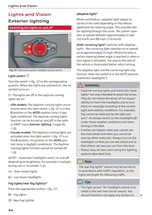 46
46 47
47 48
48 49
49 50
50 51
51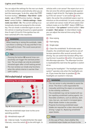 52
52 53
53 54
54 55
55 56
56 57
57 58
58 59
59 60
60 61
61 62
62 63
63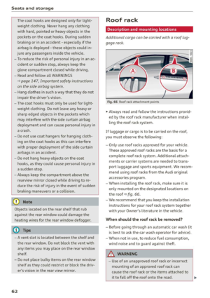 64
64 65
65 66
66 67
67 68
68 69
69 70
70 71
71 72
72 73
73 74
74 75
75 76
76 77
77 78
78 79
79 80
80 81
81 82
82 83
83 84
84 85
85 86
86 87
87 88
88 89
89 90
90 91
91 92
92 93
93 94
94 95
95 96
96 97
97 98
98 99
99 100
100 101
101 102
102 103
103 104
104 105
105 106
106 107
107 108
108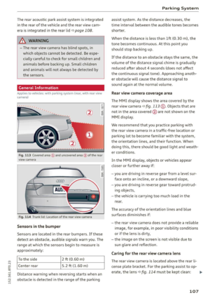 109
109 110
110 111
111 112
112 113
113 114
114 115
115 116
116 117
117 118
118 119
119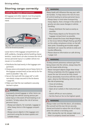 120
120 121
121 122
122 123
123 124
124 125
125 126
126 127
127 128
128 129
129 130
130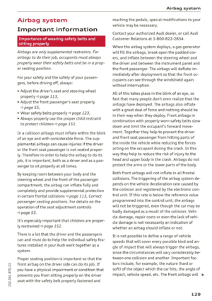 131
131 132
132 133
133 134
134 135
135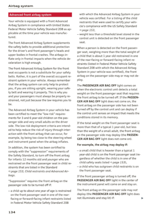 136
136 137
137 138
138 139
139 140
140 141
141 142
142 143
143 144
144 145
145 146
146 147
147 148
148 149
149 150
150 151
151 152
152 153
153 154
154 155
155 156
156 157
157 158
158 159
159 160
160 161
161 162
162 163
163 164
164 165
165 166
166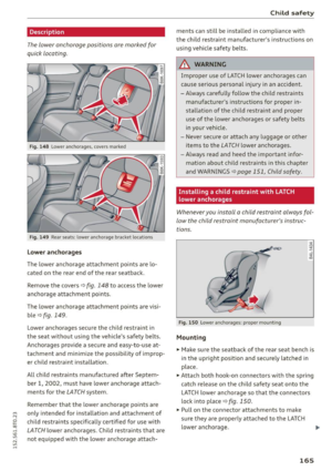 167
167 168
168 169
169 170
170 171
171 172
172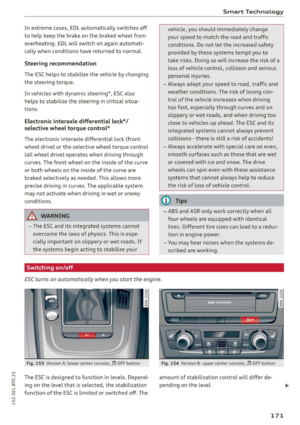 173
173 174
174 175
175 176
176 177
177 178
178 179
179 180
180 181
181 182
182 183
183 184
184 185
185 186
186 187
187 188
188 189
189 190
190 191
191 192
192 193
193 194
194 195
195 196
196 197
197 198
198 199
199 200
200 201
201 202
202 203
203 204
204 205
205 206
206 207
207 208
208 209
209 210
210 211
211 212
212 213
213 214
214 215
215 216
216 217
217 218
218 219
219 220
220 221
221 222
222 223
223 224
224 225
225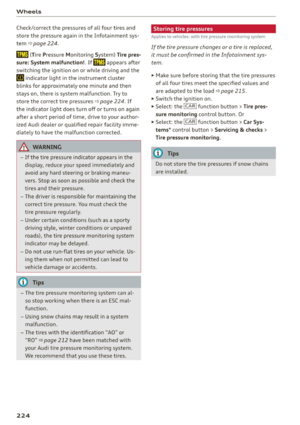 226
226 227
227 228
228 229
229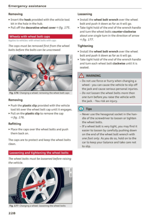 230
230 231
231 232
232 233
233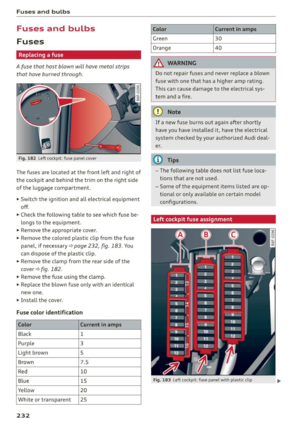 234
234 235
235 236
236 237
237 238
238 239
239 240
240 241
241 242
242 243
243 244
244 245
245 246
246 247
247 248
248 249
249 250
250 251
251 252
252 253
253 254
254 255
255 256
256 257
257 258
258 259
259 260
260 261
261 262
262 263
263