Page 161 of 200
. Failure to comply could result in
an explosion.
●
Never use jump leads when one of the bat-
teries is frozen. Danger of explosion! Even af-
ter the battery has thawed, batte")
Emergencies
on battery). Failure to comply could result in
an explosion.
●
Never use jump leads when one of the bat-
teries is frozen. Danger of explosion! Even af-
ter the battery has thawed, battery acid could
leak and cause chemical burns. If a battery
freezes, it should be replaced.
● Keep sparks, flames and lighted cigarettes
away from batteries, danger of explosion.
Failure to comply could result in an explo-
sion.
● Observe the instructions provided by the
manufacturer of the jump leads.
● Do not connect the negative cable from the
other vehicle directly to the negative terminal
of the flat battery. The gas emitted from the
battery could be ignited by sparks. Danger of
explosion.
● Do not attach the negative cable from the
other vehicle to parts of the fuel system or to
the brake line.
● The non-insulated parts of the battery
clamps must not be allowed to touch. The
jump lead attached to the positive battery
terminal must not touch metal parts of the ve-
hicle, this can cause a short circuit.
● Position the leads in such a way that they
cannot come into contact with any moving
parts in the engine compartment.
● Do not lean on the batteries. This could re-
sult in chemical burns. Note
The vehicles must not touch each other, oth-
erwise electricity could flow as soon as the
positive terminals are connected. Towing the vehicle
Introduction Vehicles with manual gearbox can be towed
using a towbar or towrope. They can also be
towed with either the front or rear wheels lif-
ted off the road.
Vehicles with automatic gearbox can be tow-
ed using a towbar or towrope. They can also
be towed with the front wheels lifted off the
road. If the vehicle is towed with the rear
wheels lifted off the road the automatic gear-
box will be damaged!
It is safer to tow a vehicle with a
towbar. A
towrope should only be used if you do not
h av
e a towbar.
Follow the instructions below when towing a
vehicle:
Notes for the driver of the towing vehicle
– Engage the clutch very gently when starting
to move or on vehicles with automatic gear-
box press the accelerator carefully. –
On vehicles with a manual gearbox, the
towrope must be taut before driving off.
Maximum towing speed is 50 km/h (31
mph).
Note
s for the driver of the towed vehicle
– The ignition should be switched on so that
the steering wheel lock is not engaged and
the turn signals, horn and windscreen wip-
ers and washers can be used.
– Put the gear lever in neutral or move the se-
lector lever to position N (automatic gear-
bo
x).
The brake servo and power steering only
work when the engine is running. Considera-
bly more effort is required on the brake pedal
and steering wheel when the engine is
switched off.
Ensure the towrope remains taut at all times
when towing. CAUTION
● Do not tow-start the engine. Risk of engine
damage! In vehicles with a catalytic convert-
er, fuel that has not been burned could reach
the catalytic converter and catch fire in it.
This could damage and destroy the catalytic
converter. You may use the battery from an-
other vehicle to help you start your engine
››› page 158.
» 159
Technical specifications
Advice
Operation
Safety
Page 162 of 200

Advice
●
If, due to a fault, there is no oil in the gear-
box, the car may only be towed with the
driven wheels lifted clear of the road and
transported on a special vehicle transporter
or trailer.
● If normal towing is not possible or if the ve-
hicle is to be towed for further than 50 km,
the vehicle must be transported on a special
vehicle transporter or trailer.
● The towrope should be slightly elastic to
reduce the load on both vehicles during tow-
ing. It is advisable to use a towrope made of
synthetic fibre or similar material only.
● Do not pull too hard with the towing vehicle
and always take care to avoid jerking the tow-
rope. When towing on a loose surface there is
always a risk of overloading and damaging
the anchorage points.
● Attach the towrope or towbar only to the
towline anchorages or to the removable tow-
ing bracket ››› page 114, or ››› page 161. Note
● We recommend you use the towrope or tow-
bar available in the SEAT Original Accessories
programme from authorised SEAT dealers.
● Towing a vehicle requires a certain degree
of practical skill. Both drivers should be fa-
miliar with the technique required for towing.
Inexperienced drivers should not attempt to
tow away another vehicle or to have their ve-
hicle towed. ●
Note the legal regulations concerning tow-
ing, particularly those regarding the signal-
ling of the towed and towing vehicle.
● The towrope must not be twisted, as under
certain circumstances this could unscrew the
front towline anchorage. Towline anchorage
Fig. 131
Front bumper: towline anchorage
cover/fitting. Fitting and detaching the cover
– Press on the left of the cover as indicated
by the arrow ››› Fig. 131 .
– Pull on the cover to remove it from the front
bumper.
– To refit the cover after unscrewing the tow-
line anchorage, fit the cover and press
down on its right-hand side. The cover
must be securely engaged.
Fitting and detaching the towline anchorage
– Screw in the towline anchorage anti-clock-
wise by hand as far as it will go ››› Fig. 131
.
To tighten the towline anchorage, we recom-
mend using the box spanner, the towing eye
from another vehicle or a similar object that
can be inserted through the anchorage.
– Unscrew the towline anchorage by turning
it clockwise. CAUTION
The towline anchorage must be screwed in as
far as it will go. Otherwise there is a risk of
the screw connection shearing off during
towing or tow-starting! 160
Page 163 of 200

Emergencies
Rear Towline anchorage Fig. 132
Rear towline anchorage. The rear towline anchorage is under the rear
bumper, on the right.
Emergency locking and
unlocking
Manual locking Fig. 133
Rear door: manual locking On the front of a door with no lock cylinder
there is an emergency locking device that is
only visible when the door is open.
Locking
– Remove the cap A
››› Fig. 133 .
– Inser
t the key in the slot B and turn it in
the direction of the arrow until horizontal
(on the other direction on the right-hand
door).
– Replace the cap.
Once the door has been locked, it can no lon-
ger be opened from the outside. The door
can be opened from the inside by pulling the
door handle. Manual release of the rear lid
Fig. 134
Manual release of the rear lid In the event of a fault in the central locking
system, the rear lid can be released manual-
ly.
Release
– Fold down the backrest of the rear seat
››› page 75 .
– Inser
t the car key in the opening in the mat.
– Move it towards the arrow to release the
rear lid.
– Open the rear lid.
161
Technical specifications
Advice
Operation
Safety
Page 164 of 200

Advice
Manual release of the selector lever Fig. 135
Manual release of the selector lever. If there is a fault in the power system to the
electronic selector lever lock system (flat bat-
tery, blown fuse) or the system itself is faulty,
the selector lever cannot be moved from po-
sition
P
in the normal manner, which pre-
v
ents the vehicle from being moved. The se-
lector lever must be unlocked using the man-
ual release.
– Apply the handbrake.
– Pull gently on both sides at the front of the
selector lever cover.
– Also loosen the cover at the rear.
– Press the yellow plastic part with your fin-
ger in the direction indicated by the arrow
››› Fig. 135.
– Pre
ss the interlock button on the selector
lever knob at the same time and move the
selector lever to position N (if the selector l
ever is moved back to position
P, it will
lock again).
Changing the wiper blades Changing the windscreen wiper
blades Fig. 136
Windscreen wiper blades. Set the windscreen wiper arms to the service
position before changing the blades.
Service position for changing wiper blades
– Close the bonnet.
– Switch the ignition on and off.
– Press the lever to position 4
››› Fig. 56
››› page 69, the windscreen wiper arms are
set to the service position. Taking off the wiper blade
–
Lift the windscreen wiper arm away from
the glass moving the blade slightly in the
direction of the arm – arrow A
››› Fig. 136 .
– Ho l
d the top of the windscreen wiper arm
with one hand.
– Unlock the catch 1 with the other hand
and remove the blade in the direction of ar-
row B .
Fitting the wiper blade – Slide the blade fully until it clicks into posi-
tion.
– Check that the wiper is correctly secured.
– Fold the windscreen wiper arm back down
onto the glass.
– Switch the ignition on and press the lever
to position 4
››› Fig. 56 ››› page 69, the
windscreen wiper arms are set to the basic
position.
162
Page 165 of 200

Fuses and bulbs
Changing the rear window wiper
blade* Fig. 137
Rear window wiper blade. Taking off the wiper blade
–
Lift the rear window wiper arm away from
the glass moving the blade slightly in the
direction of the arm – arrow A
››› Fig. 137 .
– Ho l
d the top of the rear window wiper arm
with one hand.
– Unlock the catch 1 with the other hand
and remove the blade in the direction of ar-
row B .
Fitting the wiper blade – Slide the blade fully until it clicks into posi-
tion.
– Check that the wiper is correctly secured.
– Fold the rear window wiper arm back down
onto the glass. Fuses and bulbs
Fuses Introduction Due to the constant updating of vehicles,
fuse assignments based on equipment and
the use of the same fuse for various electrical
components, it is not possible to provide an
up-to-date summary of the fuse positions for
the electrical components at the time this
manual was printed. For detailed information
about the fuse positions, please consult a
technical service.
In general, a fuse can be assigned to various
electrical components. Likewise, an electrical
component can be protected by several
fuses.
Only replace fuses when the cause of the
problem has been solved. If a newly inserted
fuse blows after a short time, you must have
the electrical system checked by a special-
ised workshop as soon as possible.
Additional information and warnings:
● Working in the engine compartment
››› page 132 . WARNING
The high voltages in the electrical system can
give serious electrical shocks, causing burns
and even death!
● Never touch the electrical wiring of the igni-
tion system.
● Take care not to cause short circuits in the
electrical system. WARNING
Using unsuitable fuses, repairing fuses or
bridging a current circuit without fuses can
cause a fire and serious injury.
● Never use a fuse with a higher value. Only
replace fuses with a fuse of the same amper-
age (same colour and markings) and size.
● Never repair a fuse.
● Never replace a fuse by a metal strip, staple
or similar. CAUTION
● To prevent damage to the vehicle's electric
system, before replacing a fuse always turn
off the ignition, the lights and all electrical
elements and remove the key from the igni-
tion.
● If you replace a fuse with higher-rating
fuse, you could cause damage to another part
of the electrical system.
● Protect the fuse boxes when open to pre-
vent the entry of dust or humidity as they can
damage the electrical system. » 163
Technical specifications
Advice
Operation
Safety
Page 166 of 200

Advice
Note
● One component may have more than one
fuse.
● Several components may run on a single
fuse. Fuses on the dash panel
Fig. 138
Bottom of the dash panel: fuse cov-
er. Fig. 139
Diagram of the fuse box to the
left/right of the steering wheel Only replace fuses with a fuse of the same
amperage (same colour and markings) and
size.
Identifying fuses situated below the driver-
side dash panel by coloursColourAmp rating
Purple3
Light brown5
Brown7.5
Red10
Blue15
Yellow20
White or trans-
parent25
ColourAmp rating
Green30
Orange40 Opening and closing the fuse box
●
Carefully tilt the cover in the direction indi-
cated by the arrow and remove it ››› Fig. 138.
● After changing the fuse, replace the cover
on the dash panel in the direction opposite
that is indicated by the arrow so that the cov-
er tabs fit into the slots on the dash panel.
Subsequently, press down on the cover to
close. CAUTION
● Always carefully remove the fuse box cov-
ers and refit them correctly to avoid problems
with your vehicle.
● Protect the fuse boxes when open to avoid
the entry of dust or humidity. Dirt and humid-
ity inside fuse boxes can cause damage to
the electrical system. Note
In the vehicle, there are more fuses than
those indicated in this chapter. These should
only be changed by a specialised workshop. 164
Page 167 of 200
. Fig. 141
Battery: fuse cover (version 2). ●
Press the flexible tabs on the fuse box cov-
er in th")
Fuses and bulbs
Changing fuses in the engine
compartment Fig. 140
Battery: fuse cover (version 1). Fig. 141
Battery: fuse cover (version 2). ●
Press the flexible tabs on the fuse box cov-
er in the direction indicated by the arrows 1 ›››
Fig. 140 .
● Remo
ve the cover by sliding it in the direc-
tion indicated by arrow 2 .
● Use a flat-headed screwdriver to unlock the
holes 3 .
● Open the cover in the direction indicated
by the arrow 4 .Replacing a blown fuse
Fig. 142
Image of a blown fuse Preparation
● Switch off the ignition, lights and all elec-
trical equipment.
● Open the corresponding fuse box
››› page 164 .
Identif y
ing a blown fuse
A fuse is blown if its metal strip is ruptured
››› Fig. 142.
Point a lamp at the fuse. This will make it
easier to see if the fuse is blown.
To replace a fuse ● Remove the fuse.
● Replace the blown fuse by one with an
identical amperage rating (same colour and
mark
ings) and identical size ››› .
»
165
Technical specifications
Advice
Operation
Safety
Page 168 of 200

Advice
● Replace the cover again or close the fuse
box lid. CAUTION
If you replace a fuse with higher-rating fuse,
you could cause damage to another part of
the electrical system. Changing bulbs
Introduction Changing bulbs requires a certain degree of
practical skill. If in doubt, we recommend you
have defective bulbs changed by a special-
ised service or, in case of an emergency,
seek professional assistance.
●
Switch off the ignition and all of the lights
before changing a bulb.
● Do not touch the glass part of the bulb with
your bare hands. The fingerprints left on the
glass will vaporise as a result of the heat gen-
erated by the bulb, reducing bulb life and
causing condensation on the reflector sur-
face, thus reducing effectiveness.
● A bulb must only be replaced by one of the
same type. The type is indicated on the bulb,
either on the glass part or on the base.
● There is a storage area for the bulb box in
the spare wheel well or below the carpet in
the luggage compartment. The light source used for each function is lis-
ted below:
Double headlights
H7 Long Life
H7
W5W Long Life PY21W NA P21W Super Long Life WARNING
● Take particular care when working on com-
ponents in the engine compartment if the en-
gine is warm. Risk of burns.
● Bulbs are highly sensitive to pressure. The
glass can break when you touch the bulb,
causing injury.
● The high voltage element of gas discharge
bulbs* (xenon light) must be handled correct-
ly. Otherwise, there is a risk of death.
● When changing bulbs, please take care not
to injure yourself on sharp parts in the head-
light housing. CAUTION
● Remove the ignition key before working on
the electric system. Otherwise, a short circuit
could occur.
● Switch off the lights and the parking light
before changing a bulb. Dipped beam:
Main beam:
Side lights:
Turn signals:
Daytime driving lights: For the sake of the environment
Please ask your specialist retailer how to dis-
pose of used bulbs in the proper manner. Note
● Depending on weather conditions (cold or
wet), the front lights, the fog lights, the rear
lights and the turn signals may be temporari-
ly misted. This has no influence on the useful
life of the lighting system. By switching on
the lights, the area through which the beam
of light is projected will quickly be demisted.
However, the edges may continue to be mis-
ted.
● Please check at regular intervals that all
lighting (especially the exterior lighting) on
your vehicle is functioning properly. This is
not only in the interest of your own safety,
but also that of all other road users.
● Before changing a bulb, make sure you
have the correct new bulb.
● Do not touch the glass part of the bulb with
your bare hands, use a cloth or paper towel
instead. Otherwise, the fingerprints left on
the glass will vaporise as a result of the heat
generated by the bulb, they will be deposited
on the reflector and damage its surface. 166
 1
1 2
2 3
3 4
4 5
5 6
6 7
7 8
8 9
9 10
10 11
11 12
12 13
13 14
14 15
15 16
16 17
17 18
18 19
19 20
20 21
21 22
22 23
23 24
24 25
25 26
26 27
27 28
28 29
29 30
30 31
31 32
32 33
33 34
34 35
35 36
36 37
37 38
38 39
39 40
40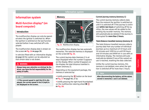 41
41 42
42 43
43 44
44 45
45 46
46 47
47 48
48 49
49 50
50 51
51 52
52 53
53 54
54 55
55 56
56 57
57 58
58 59
59 60
60 61
61 62
62 63
63 64
64 65
65 66
66 67
67 68
68 69
69 70
70 71
71 72
72 73
73 74
74 75
75 76
76 77
77 78
78 79
79 80
80 81
81 82
82 83
83 84
84 85
85 86
86 87
87 88
88 89
89 90
90 91
91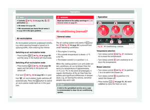 92
92 93
93 94
94 95
95 96
96 97
97 98
98 99
99 100
100 101
101 102
102 103
103 104
104 105
105 106
106 107
107 108
108 109
109 110
110 111
111 112
112 113
113 114
114 115
115 116
116 117
117 118
118 119
119 120
120 121
121 122
122 123
123 124
124 125
125 126
126 127
127 128
128 129
129 130
130 131
131 132
132 133
133 134
134 135
135 136
136 137
137 138
138 139
139 140
140 141
141 142
142 143
143 144
144 145
145 146
146 147
147 148
148 149
149 150
150 151
151 152
152 153
153 154
154 155
155 156
156 157
157 158
158 159
159 160
160 161
161 162
162 163
163 164
164 165
165 166
166 167
167 168
168 169
169 170
170 171
171 172
172 173
173 174
174 175
175 176
176 177
177 178
178 179
179 180
180 181
181 182
182 183
183 184
184 185
185 186
186 187
187 188
188 189
189 190
190 191
191 192
192 193
193 194
194 195
195 196
196 197
197 198
198 199
199