Page 153 of 200

Emergencies
●
If the anti-theft wheel bolt is overly tight-
ened, this could damage the bolt and the
adapter. Note
● The set of anti-theft wheel bolts or the
adapter are available from authorised SEAT
dealers.
● Please observe the relevant local legal reg-
ulations when changing the wheel. Preparation work
Some preparation is required before chang-
ing a wheel:
– If you have a flat tyre, stop the vehicle as
far away as possible from moving traffic.
The surface must be horizontal.
– All vehicle occupants should leave the ve-
hicle . Vehicle occupants should wait in a
s af
e place, e.g. behind the roadside crash
barrier) while the wheel is being changed.
– Switch off the ignition and engage neutral
or move the selector lever on the automatic
g
earbox to position P.
– Apply the handbrake firmly.
– If t
owing a trailer, unhitch it. –
Take the vehicle tool kit ››
› page 150 and
the spare wheel ››› page 150 out of the lug-
gage compartment.
Wheel trim Removing
– Place the hook from the vehicle tool kit on
the reinforced edge of the wheel trim.
– Insert the box spanner through the hook,
supporting it on the tyre and remove the
wheel trim.
Fitting – First press the wheel trim onto the wheel at
the cut out designed for the valve. Then
press the wheel trim on both sides in the
direction of the valve so that it fits correctly
in place around all the perimeter. CAUTION
● Press down by hand, do not hit the wheel
trim! Knocking it sharply, particularly at
points where the wheel trim has not yet been
inserted, could result in damage to the wheel
trim guiding and centring elements.
● Before fitting the trim on a steel wheel at-
tached with an anti-theft wheel bolt, make
sure the bolt is in the hole in the valve area
››› page 154, Anti-theft wheel bolts*. ●
Where trim is fitted at a later date, ensure
enough air inflow is guaranteed in order to
cool the brake system. Wheel bolt caps
Fig. 123
Pull off the wheel bolt cap. Removing
– Insert the plastic clip into the cap until the
inner retaining notches on the clips touch
the collar of the cap and then remove it
››› Fig. 123 .
Fittin g
– In
sert the caps as far as they will go over
the wheel bolts.
The wheel bolt caps are stored in a box on
the spare wheel or in the spare wheel well.
151
Technical specifications
Advice
Operation
Safety
Page 154 of 200

Advice
Wheel bolts The wheel bolts
are m atched to the rims.
When installing different wheels, e.g. to fit
light alloy wheels or wheels with winter tyres,
it is important to use the correct wheel bolts
with the right length and correctly shaped
bolt heads. This is essential for a secure fit of
the wheels and for proper operation of the
brake system.
Changing a wheel If possible, change the wheel on a level sur-
face.
– Pull off the hub cap ›››
page 151 or the
wheel bolt covers ›››
page 151.
– First loosen the anti-theft wheel bolts and
then the other wheel bolts ›››
page 152.
– Raise the vehicle until the wheel to be
changed is no longer touching the ground
››› page 153 .
– Remo
ve the wheel bolts and place them on
a clean surface (cloth, paper, etc.).
– Take off the wheel.
– Lift the spare wheel into position and tight-
en the wheel bolts lightly.
– Lower the vehicle. –
Tighten the wheel bolts firmly in diagonal
sequence with the box spanner and then
the anti-theft wheel bolt ››› page 152.
– Replace the hub cap and/or the bolt cov-
ers. Note
● All bolts must be clean and turn easily.
● Never grease or oil the wheel bolts!
● Note the direction of rotation when putting
on a tyre with a directional tread pattern
››› page 144. After changing a wheel
Tasks that must be carried out after changing
a wheel:
– Place the wheel with the defective tyre in
the spare wheel well and secure it using a
special bolt ›››
page 146 .
– Put
the vehicle tools back in their storage
location.
– Check the tyre pressure of the newly fitted
s
pare wheel as soon as possible.
– Have the tightening torque of the wheel
bo
lts checked as soon as possible with a
torque wrench.
– Have the flat tyre replaced or ask an Official
Service about the possibility of repair. Note
● If you notice that the wheel bolts are rusty
and difficult to turn when changing a wheel,
they must be replaced before having the
tightening torque checked.
● Drive carefully and at moderate speeds un-
til the tightening torque of the wheel bolts
has been checked. Loosening and tightening wheel bolts
Fig. 124
Changing a wheel: loosen the wheel
bolts. 152
Page 155 of 200

.
– Grip the end of the box spanner and turn
the wheel bolt about one turn anti-clock-
w i
se")
Emergencies
Loosening wheel bolts – Fit the box spanner as far as it will go over
the wheel bolt 1)
.
– Grip the end of the box spanner and turn
the wheel bolt about one turn anti-clock-
w i
se ››› Fig. 124.
Tightening wheel bolts – Fit the box spanner as far as it will go over
the wheel bolt 1)
.
– Grip the box spanner as close to the end as
possible and tighten the bolt firmly by turn-
ing clockwise. WARNING
The wheel bolts should only be loosened
slightly (about one turn) before raising the
vehicle with the jack. Risk of accident! Note
If the wheel bolt is very tight, it may be pos-
sible to loosen it by pushing down the end of
the box spanner carefully with your foot. Hold
on to the vehicle for support and take care
not to slip. Lifting the vehicle
Fig. 125
Changing a wheel: jack position
points. Fig. 126
Fitting the jack. To place the jack, locate the jacking point un-
der the door sill closest to the wheel to be
changed
››› Fig. 125 . The jacking point is di-
r ectly
underneath the stamp on the door sill.
– Turn the crank handle on the jack to wind it
up under the jacking point until its claw is
directly below the jacking point of the door
sill.
»1)
The corresponding adapter is required to unscrew
or tighten the anti-theft wheel bolts ››› page 154.
153
Technical specifications
Advice
Operation
Safety
Page 156 of 200

Advice
– Adjust the jack so that its claw surrounds
the jacking point on the door sill ››› Fig. 126
- B underneath the stamp on the door sill.
– Make sure that the base of the jack is en-
tirely supported on a flat surface and that it
is vertical ››› Fig. 126 to the point where the
c l
aw surrounds the jacking point on the
door sill.
– Continue to wind up the jack using the
crank handle until the defective wheel is
clear off the ground.
Anti-theft wheel bolts* Fig. 127
Anti-theft wheel bolt with adapter. On vehicles fitted with anti-theft wheel bolts
(one bolt per wheel) these bolts can only be
loosened or tightened using a factory-sup-
plied adapter.
– Pull off the hub cap or bolt cover. –
Insert the adapter B
››› Fig. 127 with its
t oothed s
ide as far as it will go on the inte-
rior toothing of the anti-theft wheel bolt A so that only the outer hexagonal is protrud-
ing.
– Fit the box spanner as far as it will go over
adapter B .
– Loosen or firmly tighten the wheel bolt
››› page 152 .
– Af t
er removing the adapter, replace the hub
cap or the anti-theft wheel bolt cover.
– Have the tightening torque of the wheel
bo
lts checked as soon as possible with a
tor
que wrench.
Note down the code number stamped on the
front of the adapter or on the front of the anti-
theft wheel bolt. You will need this number to
obtain a spare adapter from the SEAT original
accessories programme.
We recommend you always carry the wheel
bolt adapter in the vehicle. It should be stor-
ed in the vehicle tool kit.
Tyre repairs TMS (Tyre Mobility System)* The Tyre Mobility System is stored in a box
under the carpet in the boot.Using the Tyre Mobility System you can relia-
bly seal tyres damaged by foreign bodies,
provided that cuts or punctures are no larger
than approx. 4 mm in diameter. Do not re-
move the foreign bodies, e.g. bolts or nails,
from the tyre!
The tyre must be repaired immediately.
The repair made using the Tyre Mobility Sys-
tem
under no circumstances replaces
perm
a-
nent
tyre repair and should only be used to
drive to the nearest official service.
The Tyre Mobility System kit shall not be
used:
● If the wheel rim has been damaged,
● when the outside temperature is below
-20 °C (-4 °F),
● on slashes or punctures larger than 4 mm,
● if the sidewall of the wheel has been dam-
aged,
● If you have been driving with very low tyre
pressure or a completely flat tyre
● If the best-before date on the air can has
expired WARNING
Read and observe the safety warnings ››› in
Introduction on page 150.
● A ty r
e filled with sealant does not have the
same performance properties as a conven-
tional tyre. 154
Page 157 of 200
.
● Avoid heavy acceleration, hard braking and
fast cornering.
● Check the tyre pressure after 10 minutes of
driving!
● The sealant is ha")
Emergencies
●
Do not drive faster than 80 km/h (50 mph).
● Avoid heavy acceleration, hard braking and
fast cornering.
● Check the tyre pressure after 10 minutes of
driving!
● The sealant is harmful to health and must
be immediately rinsed from affected skin. For the sake of the environment
Used or out-of-date sealant must be disposed
of in line with environmental protection regu-
lations. Note
● Observe the usage instructions provided by
the snow chain manufacturer.
● A new can of sealant can be acquired from
the selection of SEAT Original Accessories.
● Change the tyre repaired using the Tyre
Mobility System as soon as possible or ask
an official service about the possibility of re-
pairing it for you. Components of the Tyre Mobility
System*
Fig. 128
Contents of the Tyre Mobility System. The Tyre Mobility System contains the follow-
ing components:
An adapter to fit and remove the valve
Sticker indicating the speed: “max. 80
km/h” or “max. 50 mph”
Flexible filling hose with cap
Compressor
Flexible tyre inflating hose
Tyre pressure gauge
Air release screw
ON/OFF button
12 V cable connector ››› page 79
Can of sealant
1 2
3
4
5
6
7
8
9
10 Spare valve
The valve extractor 1
››› Fig. 128 has a slot
in its lo
wer end that fits onto the valve insert.
This is used to remove the valve insert from
the tyre and to replace it. This is also valid for
the spare valve insert 11 .
Work prior to using the Tyre Mobility
System The following jobs must be performed before
using the Tyre Mobility System:
– If you have a flat tyre, stop the vehicle well
away from moving traffic. Stop on flat, solid
ground.
– All vehicle occupants should leave the ve-
hicle . Vehicle occupants should wait in a
s af
e place (e.g. behind the roadside crash
barrier) while the wheel is being changed.
– Switch off the ignition and engage neutral
or move the selector lever on the automatic
g
earbox to position P.
– Apply the handbrake firmly.
– Check
whether the tyre can be repaired us-
ing the Tyre Mobility System ›››
page 154.
– If towing a trailer, unhitch it.
– Remove the Tyre Mobility System from the
boot
. »
11
155
Technical specifications
Advice
Operation
Safety
Page 158 of 200

Advice
– Fix the sticker 2
››› Fig. 128
›
›› page 155
onto the dash panel where the driver will
see it.
– Do not remove the foreign body, e.g. bolts
or nails, from the tyre.
– Unscrew the tyre valve cap.
– Using the valve extractor 1 , unscrew the
valve insert and place it on a clean surface
(cloth, paper, etc.)
Filling and inflating the tyre Filling the tyre
– Shake the tyre sealant can 10
››› Fig. 128
››› page 155 thoroughly several times.
– Att ac
h the flexible filling hose 3 onto the
can 10 . The foil sealing the can will be au-
tomatically pierced.
– Remove the cap from the flexible filling
hose 3 and insert the open end as far as it
will go into the tyre valve.
– Hold the can 10 upside down and fill the
complete contents of the can into the tyre.
– Remove the empty can from the tyre.
– Screw the valve insert back into the tyre
valve using the valve extractor 1 .Inflating the tyre
–
Screw the tyre filling hose 5
››› Fig. 128
››› page 155 firmly onto the tyre valve.
– Make sure that the bleed screw 7 is
closed.
– Start the vehicle engine and leave it run-
ning.
– Plug connector 9 into the 12-volt power
socket.
– Turn on the air compressor with switch 8 .
– Leave the air compressor running until the
tyre pressure has reached 2.0 -2.5 bar
(29-36 psi/200-250 kPa). The max. operat-
ing time for the compressor is 8 minutes
››› !
– Switch the compressor off.
– When an air pressure of 2.0-2.5 bar
(29-36 psi/200-250 kPa) cannot be
reached, unscrew the flexible tube 5 from
the tyre valve.
– Drive the vehicle approx. 10 metres for-
wards or backwards, so that the sealant
can “spread evenly” in the tyre.
– Screw the flexible hose from the air com-
pressor 5 back onto the tyre valve and re-
peat the inflation process.
– If the pressure is still lower than specified,
the tyre is too badly damaged. The tyre can- not be repaired using the tyre sealant kit
››› .
– Switch the compressor off.
– Unscrew the flexible hose 5 from the tyre
valve.
When a tyre pressure of 2.0-2.5 bar
(29-36 psi/200-250 kPa) is reached, you can
continue driving at a max. speed of 80 km/h
(50 mph).
Check the tyre pressure after 10 minutes of
driving ››› page 157 . WARNING
● The flexible tyre filling hose and the air
compressor may heat up during the filling
process. Risk of injury!
● Do not place the hot flexible tyre filling
hose or hot air compressor on top of flamma-
ble materials. Risk of fire!
● If the tyre cannot be inflated to a minimum
pressure of 2.0 bar (29 psi/200 kPa), then
the tyre is too badly damaged. The sealing
product is unable to seal the tyre . Do not
continue driving and obtain professional as-
sistance. CAUTION
Do not use the air compressor for longer than
8 minutes at a time. Risk of overheating! Be-
fore using the air compressor again, leave it
to cool down for several minutes. 156
Page 159 of 200
:
– Do not drive on! The tyr e ca")
Emergencies
Check after 10 minutes of driving Check the tyre pressure after 10 minutes of
driving!
If the tyre pressure is less than 1.3 bar
(18.8 psi/130 kPa):
– Do not drive on! The tyr e cannot be suffi-
ciently filled using the tyre repair kit.
– See professional assistance.
If the tyre pressure is greater than 1.3 bar
(18.8 psi/130 kPa): – Correct the tyre pressure again to the cor-
rect value (see inside of the fuel tank flap).
– Carefully drive to the nearest specialised
workshop at a maximum speed of 80 km/h
(50 mph).
Jump-starting Introduction If the engine fails to start because of a dis-
charged battery, the battery can be connec-
ted to the battery of another vehicle to start
the engine. Suitable jump leads are required.
Both batteries need to have nominal voltage
of 12 V. The
capacity (Ah) of the back-up bat- t
er
y should not be notably less than the
drained battery.
Jump leads
The jump leads must be heavy enough to car-
ry the starter current and must be fitted with
insulated battery clamps. Refer to the instruc-
tions given by the manufacturer.
Positive cable – usually red
Neg
ative cable
– usually black WARNING
● A flat battery can also freeze at tempera-
tures slightly below to 0 °C (32 °F). Do not at-
tempt to start the vehicle with a frozen bat-
tery. Risk of explosion!
● Please note the safety warnings referring to
working in the engine compartment
››› page 132.
● The non-in s
ulated parts of the battery
clamps must not be allowed to touch. Addi-
tionally, the jump lead attached to the posi-
tive battery terminal must not touch metal
parts of the vehicle. Risk of short circuit!
● Do not connect the negative lead to the
negative terminal of the discharged battery.
In the event of sparks when starting the en-
gine, the explosive gas given off by the bat-
tery could catch fire.
● Position the jump leads in such a way that
they cannot come into contact with any mov-
ing parts in the engine compartment. ●
Do not bend over the battery. Risk of acid
burns!
● The screw plugs on the battery cells must
be screwed in firmly.
● Keep sources of fire (flames, lit cigarettes,
etc.) away from the battery. - Risk of explo-
sion!
● Never use the jump leads on batteries in
which the electrolyte level is too low. Risk of
explosion and acid burns. Note
● The vehicles must not touch each other, as
electricity could flow as soon as the positive
terminals are connected.
● The discharged battery must be properly
connected to the vehicle electrical system.
● The jump leads should be checked in a spe-
cialist vehicle battery shop. 157
Technical specifications
Advice
Operation
Safety
Page 160 of 200

Advice
How to jump start: description Fig. 129
Diagram of connections for vehicles
without Start Stop system Fig. 130
Diagram of connections for vehicles
with Start Stop system Jump lead terminal connections
1. Switch off the ignition of both vehicles
››› . 2. Connect one end of the
red jump lead to
the po s
itive + terminal of the vehicle
with the flat battery A
››› Fig. 129 .
3. C
onnect the other end of the red
jump
lead to the positive terminal + in the ve-
hicle providing assistance B .
4. For vehicles without Start-Stop system:
connect one end of the black jump lead to
the negative terminal – of the vehicle
providing the current B
››› Fig. 129 .
– For
vehicles with Start-Stop system: con-
nect one end of the black jump lead X to a
suitable ground terminal, to a solid piece of
metal in the engine block, or to the engine
block itself ››› Fig. 130 .
5. C
onnect the other end of the black jump
lead X to a solid metal component bolted
to the engine block or to the engine block
itself of the vehicle with the flat battery.
Do not connect it to a point near the bat-
tery A .
6. Position the leads in such a way that they cannot come into contact with any moving
parts in the engine compartment.
Starting
7. Start the engine of the vehicle with the boosting battery and let it run at idling
speed. 8. Start the engine of the vehicle with the flat
battery and wait 2 or 3 minutes until the
engine is “running”.
Removing the jump leads
9. Before you remove the jump leads, switch off the dipped beam headlights (if they
are switched on).
10.Turn on the heater blower and heated rear window in the vehicle with the flat battery.
This helps minimise voltage peaks which
are generated when the leads are discon-
nected.
11. When the engine is running, disconnect
the l e
ads in reverse order to the details
given above.
Connect the battery clamps so they have
good metal-to-metal contact with the battery
terminals.
If the engine fails to start, switch off the start-
er after about 10 seconds and try again after
about 1 minute. WARNING
● Please note the safety warnings referring to
working in the engine compartment
››› page 132.
● The b att
ery providing assistance must have
the same voltage as the flat battery (12V) and
approximately the same capacity (see imprint 158
 1
1 2
2 3
3 4
4 5
5 6
6 7
7 8
8 9
9 10
10 11
11 12
12 13
13 14
14 15
15 16
16 17
17 18
18 19
19 20
20 21
21 22
22 23
23 24
24 25
25 26
26 27
27 28
28 29
29 30
30 31
31 32
32 33
33 34
34 35
35 36
36 37
37 38
38 39
39 40
40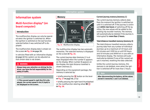 41
41 42
42 43
43 44
44 45
45 46
46 47
47 48
48 49
49 50
50 51
51 52
52 53
53 54
54 55
55 56
56 57
57 58
58 59
59 60
60 61
61 62
62 63
63 64
64 65
65 66
66 67
67 68
68 69
69 70
70 71
71 72
72 73
73 74
74 75
75 76
76 77
77 78
78 79
79 80
80 81
81 82
82 83
83 84
84 85
85 86
86 87
87 88
88 89
89 90
90 91
91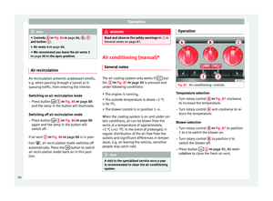 92
92 93
93 94
94 95
95 96
96 97
97 98
98 99
99 100
100 101
101 102
102 103
103 104
104 105
105 106
106 107
107 108
108 109
109 110
110 111
111 112
112 113
113 114
114 115
115 116
116 117
117 118
118 119
119 120
120 121
121 122
122 123
123 124
124 125
125 126
126 127
127 128
128 129
129 130
130 131
131 132
132 133
133 134
134 135
135 136
136 137
137 138
138 139
139 140
140 141
141 142
142 143
143 144
144 145
145 146
146 147
147 148
148 149
149 150
150 151
151 152
152 153
153 154
154 155
155 156
156 157
157 158
158 159
159 160
160 161
161 162
162 163
163 164
164 165
165 166
166 167
167 168
168 169
169 170
170 171
171 172
172 173
173 174
174 175
175 176
176 177
177 178
178 179
179 180
180 181
181 182
182 183
183 184
184 185
185 186
186 187
187 188
188 189
189 190
190 191
191 192
192 193
193 194
194 195
195 196
196 197
197 198
198 199
199