Page 113 of 200
.
● If the parking aid system is switched on
when the automatic g")
Driver assistance systems
●
To ensure that the parking aid system
works properly, the sensors must be kept
clean (e.g. free of ice).
● If the parking aid system is switched on
when the automatic gearbox selector lever is
in position P, the acoustic signal will be inter-
rupted (the car cannot be moved). Cruise control*
Introduction The cruise control system allows you to drive
at a constant speed of 30 km/h (19 mph) or
higher without having to press the accelera-
tor. However, the speed is only maintained
within the margin permitted by the engine
power and the braking effect of the engine.
The
warning lamp lights up on the general
instrument panel if cruise control is switched
on. WARNING
● For safety reasons the cruise control sys-
tem must not be used in dense traffic or
where roads conditions are poor (e.g. due to
ice, aquaplaning, loose grit, snow). – Risk of
accident!
● The programmed speed can only be re-es-
tablished if it is not too high for current traf-
fic conditions. ●
Always switch the cruise control system off
after using it in order to avoid involuntary
use. CAUTION
● The cruise control cannot maintain a con-
stant speed when the vehicle is moving
downhill. The vehicle tends to accelerate un-
der its own weight. Therefore, shift down or
use the brake pedal in good time to slow the
vehicle. Note
● In vehicles with an automatic gearbox, the
cruise control system cannot be switched on
if the selector lever is in position P, N or R.
● In vehicles with a manual gearbox, the
cruise control cannot be switched on if first
gear or reverse gear is engaged. Setting speed
Fig. 97
Turn signal and main beam headlight
lever: cruise control buttons. Setting speed
– Move knob A
››› Fig. 97 to the ON posi-
tion.
– Briefly press rocker switch B in
SET
posi-
tion when
you have reached the speed you
wish to set.
On releasing rocker switch B in
SET
, the cur-
r
ent speed is stored and will remain constant
without having to press the accelerator ped-
al.
111
Technical specifications
Advice
Operation
Safety
Page 114 of 200

Operation
Adjusting set speed Increasing speed by pressing the accelerator
pedal
–
Press the accelerator to increase the speed
of the vehicle.
– Release the accelerator and the previously
programmed speed will be resumed.
If, when pressing the accelerator, the vehicle
exceeds the programmed speed by more
than 10 km/h (6 mph) for more than 3 mi-
nutes, the set speed will be deleted. The
speed will have to be stored again.
Increasing speed by pressing switch B–
Press rocker switch B
›››
Fig. 97
››› page 111 in
RES.
– If the button is held down in the RES posi-
tion, the speed inc
reases continuously. Re-
lease the switch when the required speed
is reached. The speed is stored.
Setting a lower speed
– The set speed can be reduced by pressing
swit
ch B
›››
Fig. 97 ›
› ›
page 111 in SET.
– If the button is held down in the SET posi-
tion, the speed dec
reases continuously. Re-
lease the switch when the required speed
is reached. The speed is stored.
– On releasing the switch at speeds of less
than 30 km/h (19 mph), no speed will be set and the memory will be deleted. The ve-
hicle must be moving at a speed of over
30 km/h (19 mph) and switch
B pressed
again to SET
for it to be set.
The s
peed can be reduced by pressing the
brake pedal, which temporarily switches off
the cruise control.
Switching off cruise control
temporarily Cruise control
is switched off temporarily by
pressing switch A
››› Fig. 97
›
›› p
age 111 in
CANCEL or by pressing the brake or clutch
pedal.
The set speed is stored.
To
recover the set speed, briefly press switch
B in
RES
once you have released the brake
or c
lutch pedal.
Switching off cruise control
completely –
Move knob A
›››
Fig. 97 ›››
page 111 to
OFF . St
ar
t-Stop* System
Functioning Fig. 98
Instrument panel: Start-Stop system
button The Start-Stop system helps save fuel and re-
duce harmful and CO
2 emissions.
The system is automatically switched on ev-
ery time the ignition is switched on.
The system automatically switches off the en-
gine when the vehicle is stationary, e.g. wait-
ing at traffic lights.
The current status of the Start-Stop system is
displayed on the general instrument panel
display.
Automatic engine shut down (Stop phase)
– Stop the vehicle (if necessary using the
handbrake).
– Shift to neutral.
112
Page 115 of 200

– Press the clutch.
Switching the Start-Stop system on and off
The Start-Stop system can be switched o")
Driver assistance systems
– Release the clutch pedal.
Automatic engine start up (Start phase)
– Press the clutch.
Switching the Start-Stop system on and off
The Start-Stop system can be switched on
and off by pressing the
››› Fig. 98 button.
The w arnin
g lamp in the button will light up
when the system is switched off.
If the vehicle is in Stop phase when the but-
ton is pressed, the engine will start immedi-
ately.
The Start-Stop system works under complex
driving conditions that are difficult to detect
without specialist technology. The set of nec-
essary conditions for the correct operating of
the Start-Stop system are indicated below.
Conditions for automatic engine shut down
(Stop phase)
● Selector lever in neutral.
● Clutch pedal not pressed.
● Driver with seat belt fastened.
● Driver door closed.
● The bonnet closed.
● Vehicle stationary.
● The factory-fitted towing bracket is not elec-
trically connected to a trailer. ●
Engine at operating temperature.
● Vehicle's battery sufficiently charged.
● Vehicle not on a very steep slope
● Engine speed below 1,200 rpm.
● Vehicle battery temperature is neither too
high nor too low.
● Sufficient brake system pressure.
● Difference between outside temperature
and set interior temperature not too great
● Vehicle speed since the last time the en-
gine started was above 3 km/h (2 mph).
● Particulate filter not being cleaned
››› page 37.
● Front
wheels not overly turned (steering
wheel turned less than three quarters of a
turn)
Conditions for engine start up (Start phase)
● Clutch pedal pressed.
● Max./min. temperature set.
● Windscreen defrost function switched on.
● High blower speed.
● Start-Stop button pressed.
Conditions for automatic engine start up
without driver involvement
● Vehicle moving at a speed of over 3 km/h
(2 mph). ●
Difference between outside temperature
and interior temperature is too great
● Vehicle's battery insufficiently charged.
● Insufficient brake system pressure.
If the driver seat belt is unfastened for more
than 30 seconds in Stop phase, the engine
must be started using the ignition key.
Please observe the messages on the general
instrument panel display.
Warnings on the instrument panel display
(valid for vehicles not fitted with an
informative display)FAULT: Start-StopFault in the Start-Stop sys-
tem
START-STOP IMPOSSIBLEEngine cannot be auto-
matically shut down
START-STOP ACTIVEAutomatic engine shut
down (Stop phase)
SWITCH OFF IGNITIONSwitch the ignition off
START MANUALLYStart the engine manually WARNING
● If the engine is switched off, neither the
brake servo nor the power steering will work.
● Do not move the vehicle when the engine is
switched off. » 113
Technical specifications
Advice
Operation
Safety
Page 116 of 200

Operation
CAUTION
Switch off the Start-Stop system ››› page 107
before driving through a pool of water on the
road. Note
● The battery temperature may reflect
changes in outside temperature after several
hours. If the vehicle has been stopped out-
side at temperatures below zero or in direct
sunlight, for example, the battery tempera-
ture may take several hours to reach the val-
ues required for the correct operating of the
Start-Stop system.
● If the Climatronic system is operating auto-
matically, this could impair automatic engine
shut down under certain conditions. Towing bracket device
Driving the vehicle with a
trailer Technical requirements If your vehicle has a factory-fitted towing
bracket or is equipped with a selection of
SEAT Original Accessories, it meets all the rel-
evant technical and legal requirements.
In vehicles with a towing bracket it is possi-
ble to remove the ball joint, situated (togeth-
er with the special assembly instructions) in
the housing for the spare wheel in the vehi-
cle luggage compartment
›››
page 150, Vehi-
cle tool kit* .
Y our
vehicle is fitted with a 13-pole power
socket for the electrical connection between
the trailer and the vehicle. If the trailer you
are going to use has a 7-pin connector, the
corresponding adaptor, acquired from the
SEAT Original Accessories Catalogue, can be
used.
If a towing bracket is to be retro-fitted to the
car, it must be done according to the instruc-
tions of the towing bracket manufacturer. Note
Any queries that may arise can be directed to
an authorised SEAT dealer. Trailer weight
Trailer weight
The combined vehicle and trailer must be
balanced. To do so use the maximum permit-
ted towing bracket load. An insufficient
weight exerted by the trailer drawbar on the
ball joint of the towing bracket will have a
negative impact upon the response of the ve-
hicle-trailer assembly on the road.
Weight distribution
Distribute loads in the trailer so that heavy
objects are as near to the axle as possible.
Ensure that the objects do not move.
If the towing vehicle is empty and the trailer
loaded then the load distribution is incorrect.
However, if these conditions cannot be avoi-
ded, drive very slowly.
Tyre pressure values
Correct the tyre pressure in your vehicle to
“total load”
›››
page 144, Life cycle of tyres .
Trailer weight
Never exceed the authorised trailer weight
under any circumstances ›››
page 174, Tech-
nical specifications .
The trailer weights listed are only applicable
for altitudes up to 1000 m above sea level.
D
ue to lower air density, engine power de-
creases depending on the increase in
114
Page 117 of 200

Towing bracket device
altitude, this also reduces climbing ability,
which requires a reduction of the weight of
the vehicle with a trailer by 10% for every
1000 m increase in altitude. The weight of
the assembly is calculated by adding the ve-
hicle weight (loaded) to the trailer weight
(loaded). Always drive with special care when
towing a trailer.
The towed load and support load information
that is displayed on the towing bracket man-
ufacturers label are only values for the verifi-
cation of the device. The correct figures for
your specific vehicle, which are usually lower
than these figures, are given in the documen-
tation of your vehicle. WARNING
● Exceeding the maximum established load
per axle and the maximum towing bracket
load in addition to the maximum permitted
load or the load of the vehicle + trailer as-
sembly can cause accidents and serious inju-
ries.
● A sliding load can considerably affect the
stability and safety of the vehicle + trailer as-
sembly, resulting in accidents and serious in-
juries. Towing a trailer
Exterior mirrors
Check whether you can see enough of the
road behind the trailer with the standard rear
vision mirrors. If this is not the case, you
should have additional exterior mirrors fitted.
Observe the relevant statutory requirements
of the country you are in.
Headlights
Before starting a journey, also check the
headlight beam settings with the trailer
hitched up. Adjust the headlight range set-
tings if necessary
›››
page 62, Range control
of main lights .
Driving speed
For your own safety do not drive faster than
the maximum permitted speed indicated on
the trailer.
At all times, immediately reduce speed if you
detect the slightest swaying movement of the
trailer. Never try to “return the trailer to a
straight position” by accelerating.
Brakes
Brake in due course! If the trailer has an over-
run brake , apply the brakes gently at first and
then, firm ly
. This will prevent the jerking that
can be caused by locking of trailer wheels.
Change to a lower gear in good time before descending a slope in order to take advant-
age of the engine brake.
The trailer is incorporated into the vehicle's
anti-theft alarm system:
● When the vehicle has a factory-fitted anti-
theft alarm and a towing bracket.
● When the trailer is electrically connected to
the vehicle via the towing bracket socket.
● When the vehicle electrical device and the
towing bracket are operational.
● When the vehicle is locked and the vehi-
cle's anti-theft alarm device is activated.
Once the electrical connection is interrupted
with the vehicle trailer locked, the alarm
sounds.
Always switch off the vehicle anti-theft alarm
device before connecting or disconnecting a
trailer. The vehicle anti-theft alarm device
could cause the alarm to sound ››› page 57,
Anti-theft alarm system*.
Engine overheating
In the event that the coolant temperature
gauge needle moves to the right section of
the scale or to the red area, immediately re-
duce speed. If the control lamp flashes on
the general instrument panel, stop the vehi-
cle and switch off the engine. Wait several
minutes and check the coolant level in the
tank ››› page 138
.
»
115
Technical specifications
Advice
Operation
Safety
Page 118 of 200

Operation
Please observe the following indications
››› page 35, Coolant level and temperature
.
The coolant temperature can be reduced by
switching on the heating. WARNING
● Adjust your speed to suit the road and traf-
fic conditions.
● An electrical installation that is connected
incorrectly or by non-specialised personnel
can prevent the connection of the current to
the trailer and cause faults in the operation of
the electrical system throughout the entire
vehicle, leading to accidents and serious in-
jury.
● All electrical work must be carried out only
by specialised services.
● Never directly connect the trailer electrical
device to the electrical sockets of the reverse
driving lights or other sources of electrical
current. CAUTION
● Avoid corners, and sudden and sharp brak-
ing.
● Once the trailing arm has been removed,
place the corresponding cover on the hole of
the fastening point. This prevents dirt from
entering the hole – see the trailer system as-
sembly manual. Note
● In the event of frequent journeys with a
trailer, we recommend also having the vehi-
cle inspected in between the service inter-
vals.
● When connecting and disconnecting the
trailer, the handbrake must be applied.
● For technical reasons, trailers with LED re-
verse lights cannot be incorporated into the
vehicle anti-theft alarm system. Towing bracket device
Introduction If the vehicle is equipped with a towing
bracket device from the factory or is a genu-
ine SEAT accessory, it meets all national tech-
nical and legal requirements for towing.
Your vehicle is fitted with a 13-pin power
socket for the electrical connection between
the trailer and the vehicle. If the towing
bracket is equipped with a
7-pin connector,
y ou c
an use the corresponding available
adaptor that is a genuine SEAT accessory.
The towing device has a maximum vertical
load of 50 kg
. WARNING
● Before driving with the ball-headed bar fit-
ted, verify its correct assembly and place-
ment in the clamping bush.
● Do not use the ball-headed bar if it is not
correctly placed and fixed in the clamping
bush.
● Do not use the towing device for towing if it
is damaged or has missing parts.
● Do not modify or adapt the towing device
connection.
● Never disengage the ball-headed bar with
the trailer still hitched. CAUTION
Be careful not to damage the paint on the
bumper when handling the ball-headed bar. 116
Page 119 of 200
Towing bracket device
Description Fig. 99
Towing bracket device support for
hitching/ball-headed bar. The ball-headed bar is detachable. It is loca-
ted in the spare wheel compartment or in the
spare wheel compartment in the boot
››› page 150, Vehicle tool kit*.
Key to ››› Fig. 99
13-pin socket
Safety flange
1 2 Clamping bush
Clamping bush cap
Ball head cover
Ball-headed bar
Locking balls
Centred
Red marking on the manual regulator
Manual regulator
Key
Key slot cover
Red marking on the manual regulator
White marking on the ball-headed bar
Note
Contact an Authorised Service Partner if you
lose your key. 3
4
5
6
7
8
9
10
11
12
13
14 Placing in service position
Fig. 100
Placing in service position.
» 117Technical specifications
Advice
Operation
Safety
Page 120 of 200

Operation
Fig. 101
Service position. Before assembling, place the ball-headed bar
in service position.
–
Turn key A fully in the direction of arrow
1
››› Fig. 100 .
– Ho l
d the ball-headed bar with your left
hand.
– Pull manual regulator B outward in the di-
rection of arrow 2 and turn it fully in the
direction of arrow 3 .The manual regulator will remain in this posi-
tion.
Service position
› ››
Fig. 101
● K
ey C is in an open position – the key ar-
row points to the “unlocked” symbol. The key
cannot be removed from the key slot.
● The D locking balls may be fully inserted
into the body of the ball-headed bar by ap-
plying some pressure.
● The red E marking on the manual regula-
tor points towards the white marking on the
ball-headed bar.
● Between the manual regulator and the
body of the ball-headed bar there is a clearly
visible space of approximately 4 mm F .
Once the ball-headed bar has been posi-
tioned like this, it will be ready to be placed
in the clamping bush. WARNING
Do not use the ball-headed bar if it cannot be
correctly placed in the service position. CAUTION
The key cannot be removed from the manual
regulator key slot when it is in the service po-
sition. Assembling the ball-headed bar
Fig. 102
Placing the ball-headed bar/locking
and removing the key. 118
 1
1 2
2 3
3 4
4 5
5 6
6 7
7 8
8 9
9 10
10 11
11 12
12 13
13 14
14 15
15 16
16 17
17 18
18 19
19 20
20 21
21 22
22 23
23 24
24 25
25 26
26 27
27 28
28 29
29 30
30 31
31 32
32 33
33 34
34 35
35 36
36 37
37 38
38 39
39 40
40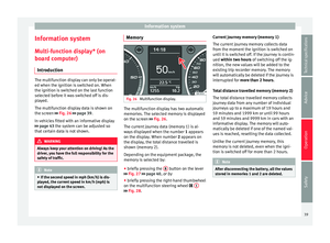 41
41 42
42 43
43 44
44 45
45 46
46 47
47 48
48 49
49 50
50 51
51 52
52 53
53 54
54 55
55 56
56 57
57 58
58 59
59 60
60 61
61 62
62 63
63 64
64 65
65 66
66 67
67 68
68 69
69 70
70 71
71 72
72 73
73 74
74 75
75 76
76 77
77 78
78 79
79 80
80 81
81 82
82 83
83 84
84 85
85 86
86 87
87 88
88 89
89 90
90 91
91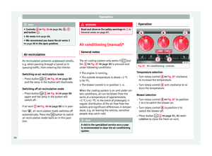 92
92 93
93 94
94 95
95 96
96 97
97 98
98 99
99 100
100 101
101 102
102 103
103 104
104 105
105 106
106 107
107 108
108 109
109 110
110 111
111 112
112 113
113 114
114 115
115 116
116 117
117 118
118 119
119 120
120 121
121 122
122 123
123 124
124 125
125 126
126 127
127 128
128 129
129 130
130 131
131 132
132 133
133 134
134 135
135 136
136 137
137 138
138 139
139 140
140 141
141 142
142 143
143 144
144 145
145 146
146 147
147 148
148 149
149 150
150 151
151 152
152 153
153 154
154 155
155 156
156 157
157 158
158 159
159 160
160 161
161 162
162 163
163 164
164 165
165 166
166 167
167 168
168 169
169 170
170 171
171 172
172 173
173 174
174 175
175 176
176 177
177 178
178 179
179 180
180 181
181 182
182 183
183 184
184 185
185 186
186 187
187 188
188 189
189 190
190 191
191 192
192 193
193 194
194 195
195 196
196 197
197 198
198 199
199