2014 NISSAN TEANA warning
[x] Cancel search: warningPage 2393 of 4801
FRONT COMBINATION LAMPEXL-127
< REMOVAL AND INSTALLATION >
C
D E
F
G H
I
J
K
M A
B
EXL
N
O P
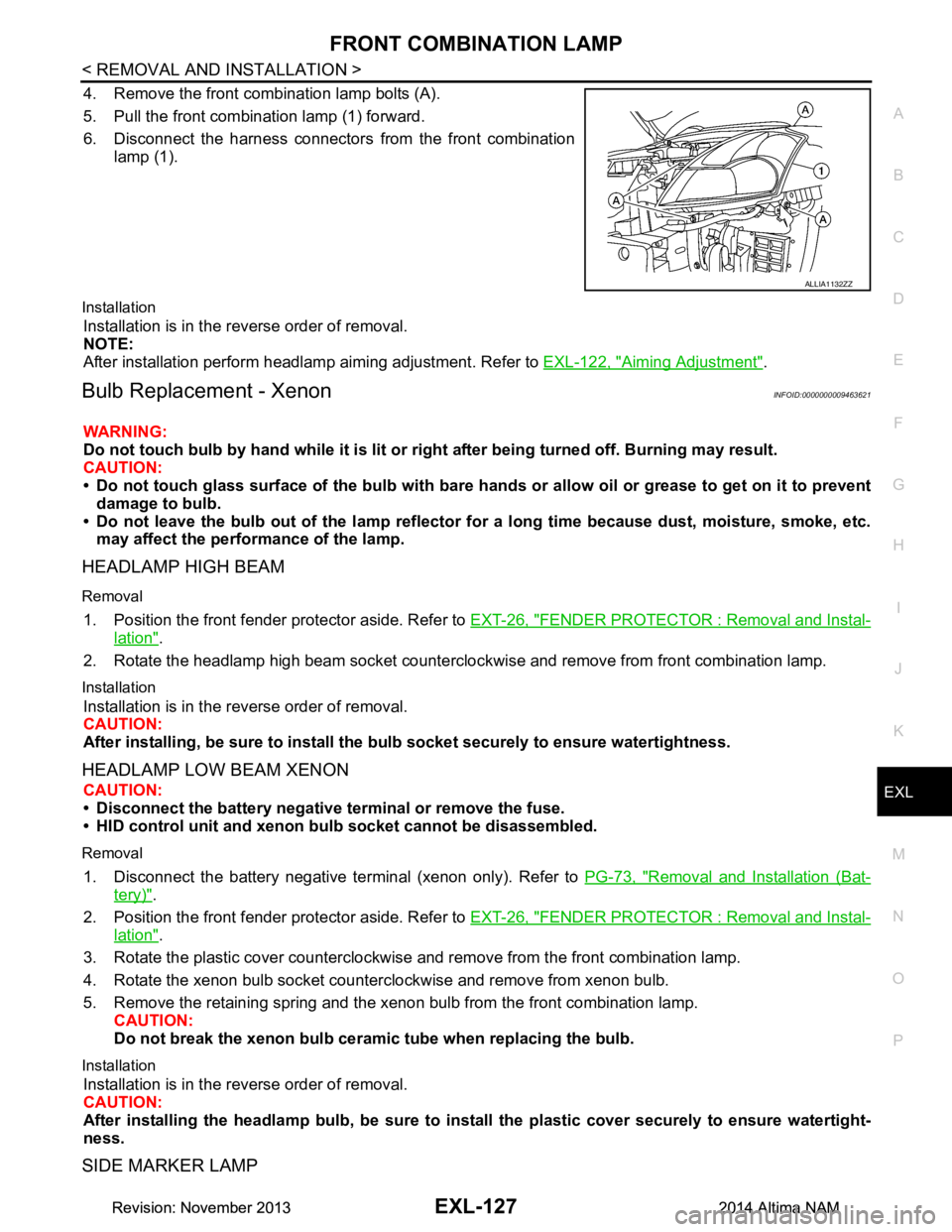
4. Remove the front combination lamp bolts (A).
5. Pull the front combination lamp (1) forward.
6. Disconnect the harness connectors from the front combination
lamp (1).
Installation
Installation is in the reverse order of removal.
NOTE:
After installation perform headlamp aiming adjustment. Refer to EXL-122, "Aiming Adjustment"
.
Bulb Replacement - XenonINFOID:0000000009463621
WARNING:
Do not touch bulb by hand while it is lit or right after being turned off. Burning may result.
CAUTION:
• Do not touch glass surface of the bulb with bare hand s or allow oil or grease to get on it to prevent
damage to bulb.
• Do not leave the bulb out of the lamp reflector fo r a long time because dust, moisture, smoke, etc.
may affect the performance of the lamp.
HEADLAMP HIGH BEAM
Removal
1. Position the front fender pr otector aside. Refer to EXT-26, "FENDER PROTECTOR : Removal and Instal-
lation".
2. Rotate the headlamp high beam socket countercloc kwise and remove from front combination lamp.
Installation
Installation is in the reverse order of removal.
CAUTION:
After installing, be sure to install the bulb socket securely to ensure watertightness.
HEADLAMP LOW BEAM XENON
CAUTION:
• Disconnect the battery negative terminal or remove the fuse.
• HID control unit and xenon bu lb socket cannot be disassembled.
Removal
1. Disconnect the battery negative te rminal (xenon only). Refer to PG-73, "Removal and Installation (Bat-
tery)".
2. Position the front fender pr otector aside. Refer to EXT-26, "FENDER PROTECTOR : Removal and Instal-
lation".
3. Rotate the plastic cover counterclockwise and remove from the front combination lamp.
4. Rotate the xenon bulb socket counterclockwise and remove from xenon bulb.
5. Remove the retaining spring and the xenon bulb from the front combination lamp. CAUTION:
Do not break the xenon bulb ceramic tube when replacing the bulb.
Installation
Installation is in the reverse order of removal.
CAUTION:
After installing the headlamp bulb, be sure to inst all the plastic cover securely to ensure watertight-
ness.
SIDE MARKER LAMP
ALLIA1132ZZ
Revision: November 20132014 Altima NAMRevision: November 20132014 Altima NAM
Page 2395 of 4801
FRONT COMBINATION LAMPEXL-129
< REMOVAL AND INSTALLATION >
C
D E
F
G H
I
J
K
M A
B
EXL
N
O P
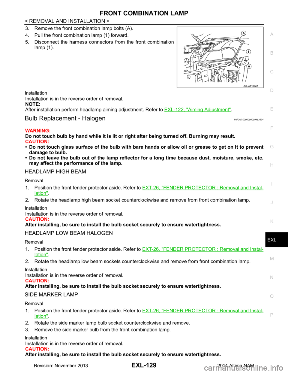
3. Remove the front combination lamp bolts (A).
4. Pull the front combination lamp (1) forward.
5. Disconnect the harness connectors from the front combination
lamp (1).
Installation
Installation is in the reverse order of removal.
NOTE:
After installation perform headlamp aiming adjustment. Refer to EXL-122, "Aiming Adjustment"
.
Bulb Replacement - HalogenINFOID:0000000009463624
WARNING:
Do not touch bulb by hand while it is lit or right after being turned off. Burning may result.
CAUTION:
• Do not touch glass surface of the bulb with bare hand s or allow oil or grease to get on it to prevent
damage to bulb.
• Do not leave the bulb out of the lamp reflector fo r a long time because dust, moisture, smoke, etc.
may affect the performance of the lamp.
HEADLAMP HIGH BEAM
Removal
1. Position the front fender pr otector aside. Refer to EXT-26, "FENDER PROTECTOR : Removal and Instal-
lation".
2. Rotate the headlamp high beam socket countercloc kwise and remove from front combination lamp.
Installation
Installation is in the reverse order of removal.
CAUTION:
After installing, be sure to install the bulb socket securely to ensure watertightness.
HEADLAMP LOW BEAM HALOGEN
Removal
1. Position the front fender protector aside. Refer to EXT-26, "FENDER PROTECTOR : Removal and Instal-
lation".
2. Rotate the headlamp low beam sockets countercloc kwise and remove from front combination lamp.
Installation
Installation is in the reverse order of removal.
CAUTION:
After installing, be sure to install the bulb socket securely to ensure watertightness.
SIDE MARKER LAMP
Removal
1. Position the front fender protector aside. Refer to EXT-26, "FENDER PROTECTOR : Removal and Instal-
lation".
2. Rotate the side marker lamp bulb socket counterclockwise and remove.
3. Remove the side marker bulb from the front combination lamp.
Installation
Installation is in the reverse order of removal.
CAUTION:
After installing, be sure to install the bulb socket securely to ensure watertightness.
ALLIA1132ZZ
Revision: November 20132014 Altima NAMRevision: November 20132014 Altima NAM
Page 2396 of 4801
EXL-130
< REMOVAL AND INSTALLATION >
TURN SIGNAL AND HAZARD WARNING LAMPS
TURN SIGNAL AND HAZARD WARNING LAMPS
Removal and InstallationINFOID:0000000009463625
REMOVAL
1. Remove the front fender protector side cover.
2. Position the fender protector aside. Refer to EXT-26, "FENDER PROTECTOR : Removal and Installa-
tion".
3. Disconnect the harness connector from the turn signal and hazard warning lamp.
4. Remove front fog lamp finisher. Refer to EXT-17, "Removal and Installation"
.
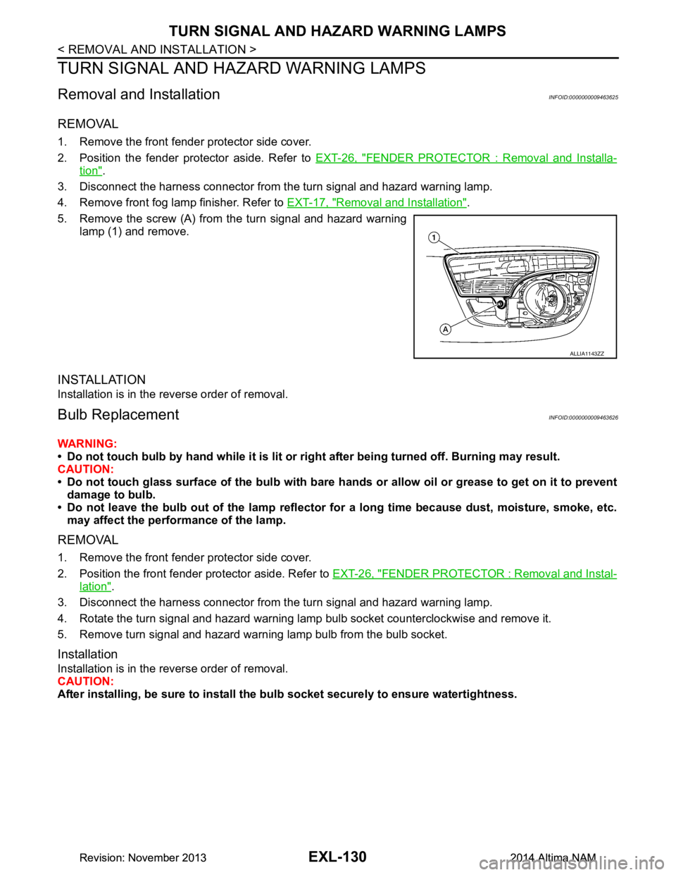
5. Remove the screw (A) from the turn signal and hazard warning lamp (1) and remove.
INSTALLATION
Installation is in the reverse order of removal.
Bulb ReplacementINFOID:0000000009463626
WARNING:
• Do not touch bulb by hand while it is lit or right after being turned off. Burning may result.
CAUTION:
• Do not touch glass surface of the bulb with bare hands or allow oil or grease to get on it to prevent
damage to bulb.
• Do not leave the bulb out of the lamp reflector fo r a long time because dust, moisture, smoke, etc.
may affect the performance of the lamp.
REMOVAL
1. Remove the front fender protector side cover.
2. Position the front fender protector aside. Refer to EXT-26, "FENDER PROTECTOR : Removal and Instal-
lation".
3. Disconnect the harness connector from the turn signal and hazard warning lamp.
4. Rotate the turn signal and hazard warning lamp bulb socket counterclockwise and remove it.
5. Remove turn signal and hazard warning lamp bulb from the bulb socket.
Installation
Installation is in the reverse order of removal.
CAUTION:
After installing, be sure to install the bu lb socket securely to ensure watertightness.
ALLIA1143ZZ
Revision: November 20132014 Altima NAMRevision: November 20132014 Altima NAM
Page 2397 of 4801
FRONT FOG LAMPEXL-131
< REMOVAL AND INSTALLATION >
C
D E
F
G H
I
J
K
M A
B
EXL
N
O P
FRONT FOG LAMP
Removal and InstallationINFOID:0000000009463627
REMOVAL
1. Remove the front fender protector side cover.
2. Position the fender protector aside. Refer to EXT-26, "FENDER PROTECTOR : Removal and Installa-
tion".
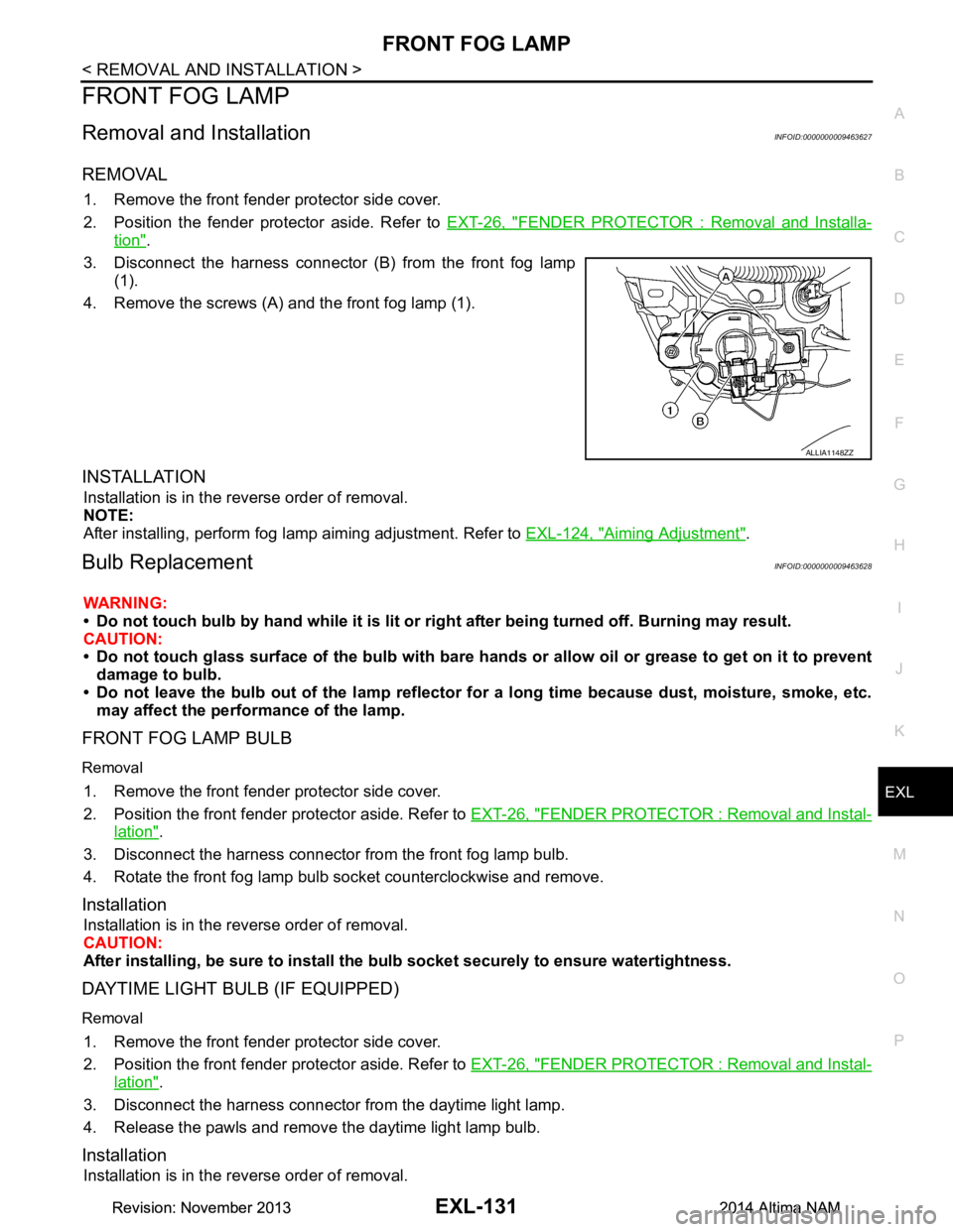
3. Disconnect the harness connector (B) from the front fog lamp (1).
4. Remove the screws (A) and the front fog lamp (1).
INSTALLATION
Installation is in the reverse order of removal.
NOTE:
After installing, perform fog lamp aiming adjustment. Refer to EXL-124, "Aiming Adjustment"
.
Bulb ReplacementINFOID:0000000009463628
WARNING:
• Do not touch bulb by hand while it is lit or right after being turned off. Burning may result.
CAUTION:
• Do not touch glass surface of the bulb with bare hand s or allow oil or grease to get on it to prevent
damage to bulb.
• Do not leave the bulb out of the lamp reflector fo r a long time because dust, moisture, smoke, etc.
may affect the performance of the lamp.
FRONT FOG LAMP BULB
Removal
1. Remove the front fender protector side cover.
2. Position the front fender pr otector aside. Refer to EXT-26, "FENDER PROTECTOR : Removal and Instal-
lation".
3. Disconnect the harness connector from the front fog lamp bulb.
4. Rotate the front fog lamp bulb socket counterclockwise and remove.
Installation
Installation is in the reverse order of removal.
CAUTION:
After installing, be sure to install the bulb socket securely to ensure watertightness.
DAYTIME LIGHT BULB (IF EQUIPPED)
Removal
1. Remove the front fender protector side cover.
2. Position the front fender pr otector aside. Refer to EXT-26, "FENDER PROTECTOR : Removal and Instal-
lation".
3. Disconnect the harness connector from the daytime light lamp.
4. Release the pawls and remove the daytime light lamp bulb.
Installation
Installation is in the reverse order of removal.
ALLIA1148ZZ
Revision: November 20132014 Altima NAMRevision: November 20132014 Altima NAM
Page 2401 of 4801
LICENSE PLATE LAMPEXL-135
< REMOVAL AND INSTALLATION >
C
D E
F
G H
I
J
K
M A
B
EXL
N
O P
LICENSE PLATE LAMP
Removal and InstallationINFOID:0000000009463633
REMOVAL
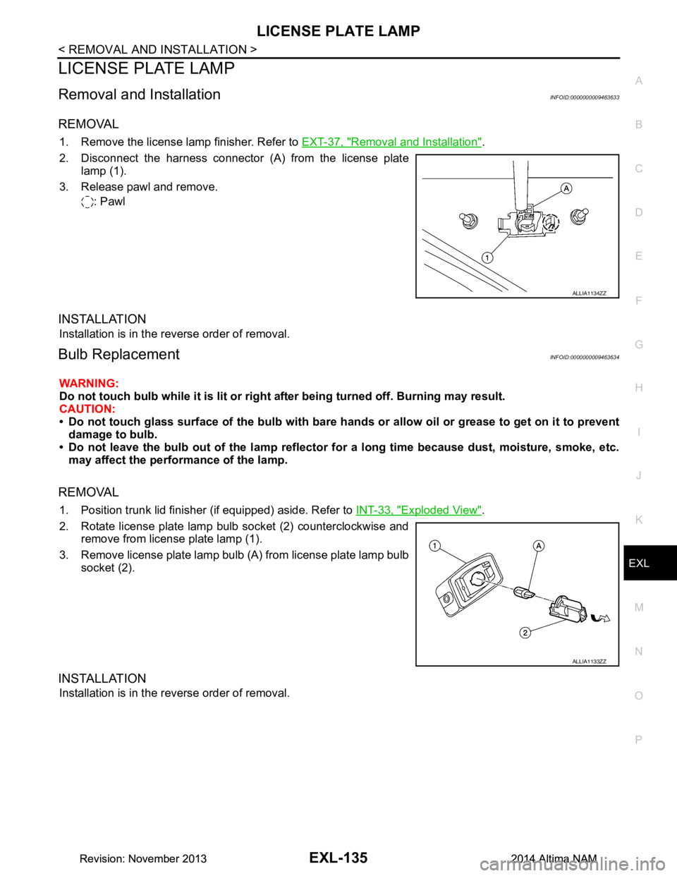
1. Remove the license lamp finisher. Refer to EXT-37, "Removal and Installation".
2. Disconnect the harness connector (A) from the license plate lamp (1).
3. Release pawl and remove. : Pawl
INSTALLATION
Installation is in the reverse order of removal.
Bulb ReplacementINFOID:0000000009463634
WARNING:
Do not touch bulb while it is lit or right after being turned off. Burning may result.
CAUTION:
• Do not touch glass surface of the bulb with bare hand s or allow oil or grease to get on it to prevent
damage to bulb.
• Do not leave the bulb out of the lamp reflector fo r a long time because dust, moisture, smoke, etc.
may affect the performance of the lamp.
REMOVAL
1. Position trunk lid finisher (if equipped) aside. Refer to INT-33, "Exploded View".
2. Rotate license plate lamp bulb socket (2) counterclockwise and remove from license plate lamp (1).
3. Remove license plate lamp bulb (A) from license plate lamp bulb socket (2).
INSTALLATION
Installation is in the reverse order of removal.
ALLIA1134ZZ
ALLIA1133ZZ
Revision: November 20132014 Altima NAMRevision: November 20132014 Altima NAM
Page 2404 of 4801
EXL-138
< REMOVAL AND INSTALLATION >
REAR COMBINATION LAMP
Bulb Replacement
INFOID:0000000009463637
WARNING:
Do not touch bulb while it is lit or right after being turned off. Burning may result.
CAUTION:
• Do not touch glass surface of the bulb with bare hands or allow oil or grease to get on it to prevent
damage to bulb.
• Do not leave the bulb out of the lamp reflector fo r a long time because dust, moisture, smoke, etc.
may affect the performance of the lamp.
REAR TURN SIGNAL LAMP BULB
Removal
1. Remove the rear combination lamp. Refer to EXL-137, "Removal and Installation".
2. Rotate the rear turn signal lamp bulb socket counterclockwise and remove.
3. Remove the rear turn signal lamp bulb from the bulb socket.
Installation
Installation is in the reverse order of removal.
CAUTION:
After installing, be sure to install the bu lb socket securely to ensure watertightness.
STOP/TAIL LAMP BULB (IF EQUIPPED)
Removal
1. Remove the rear combination lamp. Refer to EXL-137, "Removal and Installation".
2. Rotate the stop/tail lamp bulb socket counterclockwise and remove.
3. Remove the stop/tail lamp bulb from the bulb socket.
Installation
Installation is in the reverse order of removal.
CAUTION:
After installing, be sure to install the bu lb socket securely to ensure watertightness.
STOP/TAIL LAMP LED (IF EQUIPPED)
The stop/tail lamp LED is integrated into the rear combination lamp and is serviced as an assembly. Refer to
EXL-137, "Removal and Installation"
.
BACK-UP LAMP BULB
Removal
1. Remove the rear combination lamp. Refer to EXL-137, "Removal and Installation".
2. Rotate the back-up lamp bulb socket counterclockwise and remove.
3. Remove the back-up lamp bulb from the bulb socket.
Installation
Installation is in the reverse order of removal.
CAUTION:
After installing, be sure to install the bu lb socket securely to ensure watertightness.
SIDE MARKER LAMP BULB
Removal
1. Remove the rear combination lamp. Refer to EXL-137, "Removal and Installation".
2. Rotate the side marker lamp bulb socket counterclockwise and remove.
3. Remove the side marker lamp bulb from the bulb socket.
Installation
Installation is in the reverse order of removal.
CAUTION:
After installing, be sure to install the bu lb socket securely to ensure watertightness.
Revision: November 20132014 Altima NAMRevision: November 20132014 Altima NAM
Page 2405 of 4801
COMBINATION SWITCHEXL-139
< REMOVAL AND INSTALLATION >
C
D E
F
G H
I
J
K
M A
B
EXL
N
O P
COMBINATION SWITCH
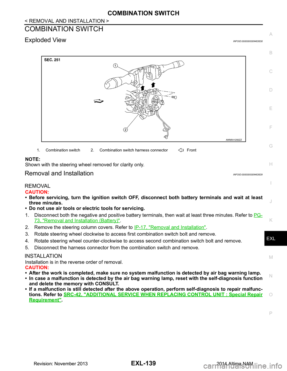
Exploded ViewINFOID:0000000009463638
NOTE:
Shown with the steering wheel removed for clarity only.
Removal and InstallationINFOID:0000000009463639
REMOVAL
CAUTION:
• Before servicing, turn the ignition switch OFF, disconnect both battery terminals and wait at least
three minutes.
• Do not use air tools or electric tools for servicing.
1. Disconnect both the negative and positive battery terminal s, then wait at least three minutes. Refer to PG-
73, "Removal and Installation (Battery)".
2. Remove the steering column covers. Refer to IP-17, "Removal and Installation"
.
3. Rotate steering wheel clockwise to access first combination switch bolt and remove.
4. Rotate steering wheel counter-clockwise to access second combination switch bolt and remove.
5. Disconnect the harness connector from the combination switch and remove.
INSTALLATION
Installation is in the reverse order of removal.
CAUTION:
• After the work is completed, make sure no system malfunction is detected by air bag warning lamp.
• In case a malfunction is detected by the air bag wa rning lamp, reset with the self-diagnosis function
and delete the memory with CONSULT.
• If a malfunction is still detected after the above operation, perform self-diagnosis to repair malfunc-
tions. Refer to SRC-42, "ADDITIONAL SERVICE WHEN RE PLACING CONTROL UNIT : Special Repair
Requirement".
AWMIA1293ZZ
1. Combination switch 2. Combination switch harness connector Front
Revision: November 20132014 Altima NAMRevision: November 20132014 Altima NAM
Page 2408 of 4801
EXL-142
< UNIT DISASSEMBLY AND ASSEMBLY >
FRONT COMBINATION LAMP
UNIT DISASSEMBLY AND ASSEMBLY
FRONT COMBINATION LAMP
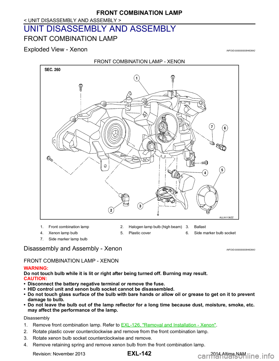
Exploded View - XenonINFOID:0000000009463642
FRONT COMBINATION LAMP - XENON
Disassembly and Assembly - XenonINFOID:0000000009463643
FRONT COMBINATION LAMP - XENON
WARNING:
Do not touch bulb while it is lit or right after being turned off. Burning may result.
CAUTION:
• Disconnect the battery negative terminal or remove the fuse.
• HID control unit and xenon bu lb socket cannot be disassembled.
• Do not touch glass surface of the bulb with bare hands or allow oil or grease to get on it to prevent
damage to bulb.
• Do not leave the bulb out of the lamp reflector fo r a long time because dust, moisture, smoke, etc.
may affect the performance of the lamp.
Disassembly
1. Remove front combination lamp. Refer to EXL-126, "Removal and Installation - Xenon".
2. Rotate plastic cover counterclockwise and remove from the front combination lamp.
3. Rotate xenon bulb socket counterclockwise and remove.
4. Remove retaining spring and remove xenon bulb from the front combination lamp.
ALLIA1136ZZ
1. Front combination lamp 2. Halogen lamp bulb (high beam) 3. Ballast
4. Xenon lamp bulb 5. Plastic cover 6. Side marker bulb socket
7. Side marker lamp bulb
Revision: November 20132014 Altima NAMRevision: November 20132014 Altima NAM