2014 NISSAN TEANA fold seats
[x] Cancel search: fold seatsPage 3190 of 4801

MA-6
< PERIODIC MAINTENANCE >
GENERAL MAINTENANCE
UNDER THE HOOD AND VEHICLE
The maintenance items listed here should be checked periodically (e.g. each time you check the engine oil or refuel).
SeatsCheck seat position controls such as seat adjusters, seatback recliner, etc. to
make sure they operate smoothly and that all latches lock securely in every po-
sition. Check that the head restrains move up and down smoothly and that the
locks (if equipped) hold securely in all latched positions. Check that the latches
lock securely for folding-down rear seatbacks. —
Seat belts Check that all parts of the seat belt system (e.g. buckles, anchors, adjusters and
retractors) operate properly and smoothly, and are installed securely. Check the
belt webbing for cuts, fraying, wear or damage. SB-5, "Inspection"
Accelerator pedal
Check the pedal for smooth operation and make sure the pedal does not catch
or require uneven effort. Keep the floor mats away from the pedal. —
Brakes Check that the brake does not pull the vehicle to one side when applied. —
Brake pedal and
booster Check the pedal for smooth operation and make sure it has the proper distance
under it when depressed fully. Check the brake booster function. Be sure to keep
the floor mats away from the pedal. BR-48
,
BR-49
Parking brake Check that the pedal has the proper travel and make sure that the vehicle is held
securely on a fairly steep hill when only the parking brake is applied. PB-4
CVT P (Park) position
mechanism On a fairly steep hill check that the vehicle is held securely with the shift selector
in the P (Park) position without applying any brakes. —
Item
Reference page
ItemReference page
Windshield washer
fluid Check that there is adequate fluid in the tank. —
Engine coolant level Check the coolant level when the engine is cold. MA-14
(QR25DE)
MA-23
(VQ35DE)
Radiator and hoses Check the front of the radiator and clean off any dirt, insects, leaves, etc., that
may have accumulated. Make sure the hoses have no cracks, deformation, de-
terioration or loose connections. —
Brake and clutch fluid
levels Make sure that the brake and clutch fluid levels are between the “MAX” and “MIN”
lines on the reservoir. MA-41
Battery
Check the fluid level in each cell. It should be between the “MAX” and “MIN” lines.
Vehicles operated in high temperatures or under severe conditions require fre-
quent checks of the battery fluid level. —
Engine drive belts Make sure that no belt is frayed, worn, cracked or oily. MA-13
(QR25DE)
MA-22
(VQ35DE)
Engine oil level Check the level on the oil level gauge after parking the vehicle on a level spot and
turning off the engine. MA-17
(QR25DE)
MA-26
(VQ35DE)
Power steering fluid
level and lines Check the level when the fluid is cold, with the engine off. Check the lines for im-
proper attachment, leaks, cracks, etc. MA-44
Exhaust system
Make sure there are no loose supports, cracks or holes. If the sound of the ex-
haust seems unusual or there is a smell of exhaust fumes, immediately locate the
trouble and correct it. MA-31
Underbody
The underbody is frequently exposed to corrosive substances such as those
used on icy roads or to control dust. It is very important to remove these sub-
stances, otherwise rust will form on the floor pan, frame, fuel lines and around the
exhaust system. At the end of winter, the underbody should be thoroughly
flushed with plain water, being careful to clean those areas where mud and dirt
can easily accumulate. —
Fluid leaks Check under the vehicle for fuel, oil, water or other fluid leaks after the vehicle
has been parked for a while. Water dripping from the air conditioner after use is
normal. If you should notice any leaks or gasoline fumes are evident, check for
the cause and correct it immediately. —
Revision: November 20132014 Altima NAM
Page 3786 of 4801

REAR SEATSE-37
< REMOVAL AND INSTALLATION >
C
D E
F
G H
I
K L
M A
B
SE
N
O P
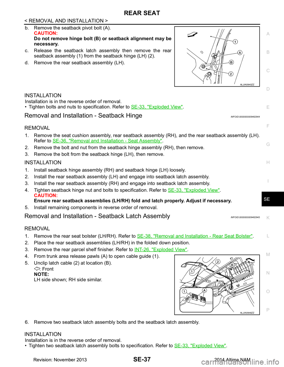
b. Remove the seatback pivot bolt (A). CAUTION:
Do not remove hinge bolt (B) or seatback alignment may be
necessary.
c. Release the seatback latch assembly then remove the rear seatback assembly (1) from the seatback hinge (LH) (2).
d. Remove the rear seatback assembly (LH).
INSTALLATION
Installation is in the reverse order of removal.
• Tighten bolts and nuts to specification. Refer to SE-33, "Exploded View"
.
Removal and Installation - Seatback HingeINFOID:0000000009462944
REMOVAL
1. Remove the seat cushion assembly, rear seatback assembly (RH), and the rear seatback assembly (LH).
Refer to SE-36, "Removal and Installation - Seat Assembly"
.
2. Remove the bolt and nut from the seatback hinge assembly (RH), then remove.
3. Remove the bolt from the s eatback hinge (LH), then remove.
INSTALLATION
1. Install seatback hinge assembly (RH) and seatback hinge (LH) loosely.
2. Install the rear seatback assembly (LH) and engage into seatback latch assembly.
3. Install the rear seatback assembly (RH) and engage into seatback latch assembly.
4. Tighten seatback hinge nut and bolts to specification. Refer to SE-33, "Exploded View"
.
CAUTION:
Ensure rear seatback assemblies (LH/RH) fold and latch properly. Adjust if necessary.
5. Install remaining components in reverse order of removal.
Removal and Installation - Seatback Latch AssemblyINFOID:0000000009462945
REMOVAL
1. Remove the rear seat bolster (LH/RH). Refer to SE-38, "Removal and Installation - Rear Seat Bolster".
2. Place the rear seatback assemblies (LH/RH) in the folded down position.
3. Remove the rear parcel shelf finisher. Refer to INT-26, "Exploded View"
.
4. From trunk area release pawls (A) to open cable guide (1).
5. Unclip latch cable (2) at location (B). : Front
NOTE:
LH side shown; RH side similar.
6. Remove two seatback latch assembly bolts and the seatback latch assembly.
INSTALLATION
Installation is in the reverse order of removal.
• Tighten two seatback latch assembly bolts to specification. Refer to SE-33, "Exploded View"
.
ALJIA0940ZZ
ALJIA0948ZZ
Revision: November 20132014 Altima NAMRevision: November 20132014 Altima NAM
Page 3802 of 4801

FRONT SEATSE-53
< UNIT DISASSEMBLY AND ASSEMBLY >
C
D E
F
G H
I
K L
M A
B
SE
N
O P
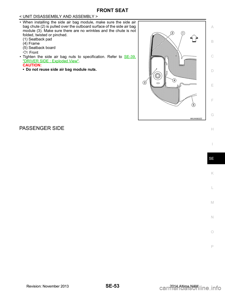
• When installing the side air bag module, make sure the side air bag chute (2) is pulled over the outboard surface of the side air bag
module (3). Make sure there are no wrinkles and the chute is not
folded, twisted or pinched.
(1) Seatback pad
(4) Frame
(5) Seatback board
: Front
• Tighten the side air bag nuts to specification. Refer to SE-39,
"DRIVER SIDE : Exploded View".
CAUTION:
• Do not reuse side air bag module nuts.
PASSENGER SIDE
AWJIA0822ZZ
Revision: November 20132014 Altima NAMRevision: November 20132014 Altima NAM
Page 3814 of 4801

FRONT SEATSE-65
< UNIT DISASSEMBLY AND ASSEMBLY >
C
D E
F
G H
I
K L
M A
B
SE
N
O P
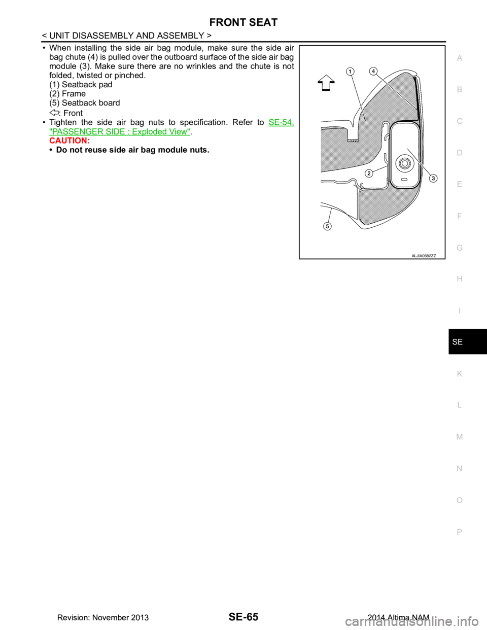
• When installing the side air bag module, make sure the side air bag chute (4) is pulled over the outboard surface of the side air bag
module (3). Make sure there are no wrinkles and the chute is not
folded, twisted or pinched.
(1) Seatback pad
(2) Frame
(5) Seatback board
: Front
• Tighten the side air bag nuts to specification. Refer to SE-54,
"PASSENGER SIDE : Exploded View".
CAUTION:
• Do not reuse side air bag module nuts.
ALJIA0682ZZ
Revision: November 20132014 Altima NAMRevision: November 20132014 Altima NAM