2014 NISSAN TEANA buttons
[x] Cancel search: buttonsPage 914 of 4801

DLK-146
< DTC/CIRCUIT DIAGNOSIS >
INTELLIGENT KEY BATTERY AND FUNCTION
INTELLIGENT KEY BATTERY AND FUNCTION
DescriptionINFOID:0000000009461895
The following functions are available when having and carrying the Intelligent Key.
• Door lock/unlock
• Trunk open
Remote control entry function and panic alarm functi on are available when operating the remote buttons.
Component Function CheckINFOID:0000000009461896
NOTE:
The Signal Tech II Tool (J-50190) can be used to perform the following functions. Refer to the Signal Tech II
User Guide for additional information.
• Check Intelligent Key relative signal strength
• Confirm vehicle Intelligent Key antenna signal strength
1.CHECK FUNCTION
With CONSULT
Check remote keyless entry receiver RKE OP E COUN1 in Data Monitor mode with CONSULT.
Is the inspection result normal?
YES >> Intelligent Key is OK.
NO >> Refer to DLK-146, "Diagnosis Procedure"
.
Diagnosis ProcedureINFOID:0000000009461897
NOTE:
The Signal Tech II Tool (J-50190) can be used to perform the following functions. Refer to the Signal Tech II
User Guide for additional information.
• Check Intelligent Key relative signal strength
• Confirm vehicle Intelligent Key antenna signal strength
1.CHECK INTELLIGENT KEY FUNCTION
Check Intelligent Key function using Signal Tech II Tool J-50190 or
Remote Keyless Entry Tester J-43241 (shown).
Does the test pass?
YES >> Intelligent Key is OK.
NO >> GO TO 2
2. CHECK INTELLIGENT KEY COMPONENTS
1. Release the lock knob at the back of the In telligent Key and remove the mechanical key.
Monitor item Condition
RKE OPE COUN1 Check that the numerical value is changing while operating with the Intelligent Key.
LEL946A
Revision: November 20132014 Altima NAMRevision: November 20132014 Altima NAM
Page 918 of 4801

DLK-150
< DTC/CIRCUIT DIAGNOSIS >
HOMELINK UNIVERSAL TRANSCEIVER
HOMELINK UNIVERSAL TRANSCEIVER
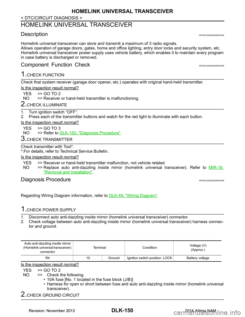
DescriptionINFOID:0000000009461904
Homelink universal transceiver can store and transmit a maximum of 3 radio signals.
Allows operation of garage doors, gates, home and office lighting, entry door locks and security system, etc.
Homelink universal transceiver power supply uses vehicl e battery, which enables it to maintain every program
in case battery is discharged or removed.
Component Function CheckINFOID:0000000009461905
1.CHECK FUNCTION
Check that system receiver (garage door opener, et c.) operates with original hand-held transmitter.
Is the inspection result normal?
YES >> GO TO 2
NO >> Receiver or hand-held transmitter is malfunctioning.
2.CHECK ILLUMINATE
1. Turn ignition switch “OFF”.
2. Press each of the transmitter buttons and watch for the red light to illuminate with each button.
Is the inspection result normal?
YES >> GO TO 3
NO >> Refer to DLK-150, "Diagnosis Procedure"
.
3.CHECK TRANSMITTER
Check transmitter with Tool*.
*:For details, refer to Technical Service Bulletin.
Is the inspection result normal?
YES >> Receiver or hand-held transmitter malfunction, not vehicle related.
NO >> Replace auto anti-dazzling inside mirror (homelink universal transceiver). Refer to MIR-19,
"Removal and Installation".
Diagnosis ProcedureINFOID:0000000009461906
Regarding Wiring Diagram information, refer to DLK-49, "Wiring Diagram".
1.CHECK POWER SUPPLY
1. Disconnect auto anti-dazzling inside mirror (homelink universal transceiver) connector.
2. Check voltage between auto anti-dazzling inside mirror (homelink universal transceiver) harness connec-
tor and ground.
Is the inspection result normal?
YES >> GO TO 2
NO >> Check the following. • 10A fuse [No. 1 located in the fuse block (J/B)]
• Harness for open or short between fuse and auto anti-dazzling inside mirror (homelink universal
transceiver).
2.CHECK GROUND CIRCUIT
Auto anti-dazzling inside mirror
(Homelink universal transceiver) connector Terminal Condition
Voltage (V)
(Approx.)
R4 10 Ground Ignition switch position: LOCK Battery voltage
Revision: November 20132014 Altima NAMRevision: November 20132014 Altima NAM
Page 2556 of 4801

GI-28
< PRECAUTION >
PRECAUTIONS
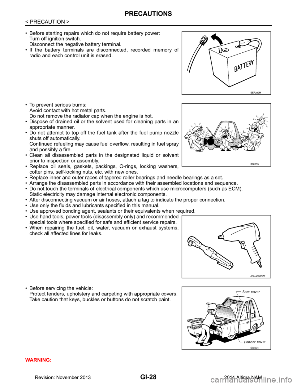
• Before starting repairs which do not require battery power:Turn off ignition switch.
Disconnect the negative battery terminal.
• If the battery terminals are disconnected, recorded memory of
radio and each control unit is erased.
• To prevent serious burns: Avoid contact with hot metal parts.
Do not remove the radiator cap when the engine is hot.
• Dispose of drained oil or the solvent used for cleaning parts in an
appropriate manner.
• Do not attempt to top off the fuel tank after the fuel pump nozzle
shuts off automatically.
Continued refueling may cause fuel overflow, resulting in fuel spray
and possibly a fire.
• Clean all disassembled parts in the designated liquid or solvent
prior to inspection or assembly.
• Replace oil seals, gaskets, packings, O-rings, locking washers, cotter pins, self-locking nuts, etc. with new ones.
• Replace inner and outer races of tapered roller bearings and needle bearings as a set.
• Arrange the disassembled parts in accordance with their assembled locations and sequence.
• Do not touch the terminals of electrical com ponents which use microcomputers (such as ECM).
Static electricity may damage internal electronic components.
• After disconnecting vacuum or air hoses, atta ch a tag to indicate the proper connection.
• Use only the fluids and lubricants specified in this manual.
• Use approved bonding agent, sealants or their equivalents when required.
• Use hand tools, power tools (disassembly only) and recommended special tools where specified for safe and efficient service repairs.
• When repairing the fuel, oil, water, vacuum or exhaust systems,
check all affected lines for leaks.
• Before servicing the vehicle: Protect fenders, upholstery and carpeting with appropriate covers.
Take caution that keys, buckles or buttons do not scratch paint.
WARNING:
SEF289H
SGI233
JPAIA0335ZZ
SGI234
Revision: November 20132014 Altima NAMRevision: November 20132014 Altima NAM
Page 2767 of 4801
![NISSAN TEANA 2014 Service Manual
HAC-118
< SYSTEM DESCRIPTION >[MANUAL AIR CONDITIONER]
SYSTEM
Control by ECM- Cooling fan control
Refer to EC-60, "COOLING FAN CONTROL : System Description (with manual air conditioner)"
(QR25DE)
NISSAN TEANA 2014 Service Manual
HAC-118
< SYSTEM DESCRIPTION >[MANUAL AIR CONDITIONER]
SYSTEM
Control by ECM- Cooling fan control
Refer to EC-60, "COOLING FAN CONTROL : System Description (with manual air conditioner)"
(QR25DE)](/manual-img/5/57390/w960_57390-2766.png)
HAC-118
< SYSTEM DESCRIPTION >[MANUAL AIR CONDITIONER]
SYSTEM
Control by ECM- Cooling fan control
Refer to EC-60, "COOLING FAN CONTROL : System Description (with manual air conditioner)"
(QR25DE)
or EC-575, "COOLING FAN CONTROL : System Description"
(VQ35DE).
- Air conditioning cut control Refer to EC-57, "AIR CONDITIONING CUT CONTROL : Sy stem Description (with manual air conditioner)"
(QR25DE) or EC-573, "AIR CONDITIONING CUT CONTROL : System Description" (VQ35DE).
Control by IPDM E/R
- Relay control
Refer to PCS-6, "RELAY CONTROL SYSTEM : System Description"
.
- Cooling fan control
Refer to EC-60, "COOLING FAN CONTROL : System Description (with manual air conditioner)"
(QR25DE)
or EC-575, "COOLING FAN CONTROL : System Description"
(VQ35DE).
Air Flow ControlINFOID:0000000009463196
DESCRIPTION
• Front air control changes duty ratio of front blower mo tor control signal to control air flow continuously. When
air flow is increased, duty ratio of front blower mo tor control signal gradually increases to prevent a sudden
increase in air flow.
• In addition to manual control, air flow control is composed of fan speed control at door motor operation.
FAN SPEED CONTROL AT DOOR MOTOR OPERATION
When mode door motor is activated while air flow is more than the specified value, front air control temporarily
reduces fan speed so that mode door moves smoothly.
Air Inlet ControlINFOID:0000000009463197
The intake door position is automatically controlled in MAX A/C and DEF modes. The intake door is controlled
by customer input in the other modes.
Air Outlet ControlINFOID:0000000009463198
Air outlet control is controlled by customer input. When t he A/C is turned off by turning the blower control dial
fully counterclockwise, the front air control retains the current selections and returns to these selections the
next time the blower control dial is turned to any fan position.
NOTE:
If ambient temperature is excessively low, D/F is se lected to prevent windshield fogging when air outlet is set
to FOOT.
Compressor ControlINFOID:0000000009463199
DESCRIPTION
In order for the IPDM E/R to complete a compress or ON request, the following conditions must be met:
1. The BCM detects a Fan ON signal from the front air control. The front air control grounds the fan ON sig-
nal monitored by the BCM when the blower speed dial is in any of the fan speed positions.
2. The BCM detects an A/C ON signal from the front air control. The front air control grounds the A/C ON sig-
nal monitored by the BCM when:
- The A/C switch is pressed. The A/C switch LED ill uminates and the front air control grounds the A/C ON
signal monitored by the BCM. Any mode c ontrol button except D/F may be selected.
- The A/C switch is OFF, and the MAX A/C button is pr essed. The A/C switch LED will automatically illumi-
nate and the front air control grounds the A/C ON signal monitored by the BCM.
- The A/C switch is OFF, and the mode button for either D/F or DEF is selected. The front air control
grounds the A/C ON signal monitored by the BCM, but it does not illuminate the A/C switch LED
NOTE:
If the compressor was engaged by pressing the D/F or DE F mode buttons, and the time spent in either mode
exceeds 1 minute, then the compressor stays reques ted, even when modes other than D/F or DEF are
selected, until either:
1. The ignition switch is turned OFF.
Revision: November 20132014 Altima NAMRevision: November 20132014 Altima NAM
Page 2801 of 4801
![NISSAN TEANA 2014 Service Manual
HAC-152
< DTC/CIRCUIT DIAGNOSIS >[MANUAL AIR CONDITIONER]
POWER SUPPLY AND GROUND CIRCUIT FOR FRONT AIR CONTROL
POWER SUPPLY AND GROUND CIRC
UIT FOR FRONT AIR CONTROL
DescriptionINFOID:00000000094632 NISSAN TEANA 2014 Service Manual
HAC-152
< DTC/CIRCUIT DIAGNOSIS >[MANUAL AIR CONDITIONER]
POWER SUPPLY AND GROUND CIRCUIT FOR FRONT AIR CONTROL
POWER SUPPLY AND GROUND CIRC
UIT FOR FRONT AIR CONTROL
DescriptionINFOID:00000000094632](/manual-img/5/57390/w960_57390-2800.png)
HAC-152
< DTC/CIRCUIT DIAGNOSIS >[MANUAL AIR CONDITIONER]
POWER SUPPLY AND GROUND CIRCUIT FOR FRONT AIR CONTROL
POWER SUPPLY AND GROUND CIRC
UIT FOR FRONT AIR CONTROL
DescriptionINFOID:0000000009463219
COMPONENT DESCRIPTION
Front air control.
The front air control has a built-in microcomputer that processes inform ation sent from various sensors
needed for air conditioner operation. The air mix door motor, the mode door motor, the intake door motor, the
blower motor and the A/C compressor are then controlled.
Component Function CheckINFOID:0000000009463220
1.CHECK OPERATION
1. Turn the blower motor dial clockwise and verify t he blower speed increases and that one of the LEDs illu-
minates on the mode switch.
2. Press the mode switches and verify that the modes change, the LEDs illuminate, and that air flows from
the various vents.
3. Turn the temperature control dial and verify the temperature changes at the selected vents.
4. Press the DEF and REC buttons and verify air flow changes.
Does it operate normally?
YES >> Inspection End.
NO >> Perform trouble diagnosis for the front air control system. Refer to HAC-152, "Diagnosis Proce-
dure".
Diagnosis ProcedureINFOID:0000000009463221
Regarding Wiring Diagram information, refer to HAC-130, "Wiring Diagram".
1.CHECK FRONT AIR CONTROL POWER SUPPLY
1. Turn ignition switch OFF.
2. Disconnect the front air control connector.
3. Turn ignition switch ON.
4. Check voltage between front air control har ness connector M37 terminals 1, 2 and ground.
Is the inspection result normal?
YES >> GO TO 3.
NO >> GO TO 2.
2.CHECK FUSE
Check fuses [Nos. 14 and 30, located in the fuse block (J/B)].
NOTE:
Refer to PG-70, "Terminal Arrangement"
.
Is the inspection result normal?
YES >> Check harness for open circuit. Repair or replace if necessary.
NO >> Check harness for short circuit. Repair or replace if necessary.
3.CHECK FRONT AIR CONTROL GROUND CIRCUIT
(+) (−)Voltage
Front air control —Ignition switch position
Connector Terminal OFF ACC ON
M37 1
Ground Battery
voltage Battery
voltage Battery
voltage
2 Approx. 0V Approx. 0V Battery
voltage
Revision: November 20132014 Altima NAMRevision: November 20132014 Altima NAM