2014 NISSAN TEANA washer fluid
[x] Cancel search: washer fluidPage 10 of 4801

< SERVICE DATA AND SPECIFICATIONS (SDS) 2014
QUICK REFERENCE CHART: ALTIMA
Fluids and Lubricants
INFOID:0000000010112411
Description Capacity (Approximate)
Metric US measure Imp measure
Fuel QR25DE
68 18 gal
15 gal
VQ35DE
Engine oil
Drain and refill With oil filter
change
QR25DE
4.6 4-7/8 qt
4 qt
VQ35DE 4.8 5-1/8 qt
4-1/4 qt
Without oil fil-
ter change QR25DE
4.3 4-1/2 qt
3-3/4 qt
VQ35DE 4.5 4-3/4 qt
4 qt
Dry engine
(engine overhaul) QR25DE
5.4 5-3/4 qt
4-3/4 qt
VQ35DE 5.3 5-5/8 qt
4-5/8 qt
Cooling system
(with reservoir tank
at MAX level) QR25DE
7.9 8-3/8 qt
7 qt
VQ35DE 9.2 9-3/4 qt
8-1/8 qt
CVT fluid RE0F10D
7.4 7-7/8 qt
6-1/2 qt
RE0F10E 8.2 8-5/8 qt
7-1/4 qt
Power steering fluid (E-PSF) 1.1 1-1/8 qt
1 qt
Brake fluid ———
Multi-purpose grease ———
Windshield washer fluid 4.5 4-3/4 qt
4 qt
Air conditioner system refrigerant 0.525 ± 0.025 kg 1.158 ± 0.055 lb 1.158 ± 0.055 lb
Air conditioner system oil 150 m5.1 fl oz
5.3 fl oz
Page 118 of 4801

BR-22
< REMOVAL AND INSTALLATION >
BRAKE PIPING
3. Disconnect the brake hose (1) from brake tube (2) at the flarenut (A) using a suitable tool and remove the lock plate (3).
4. Remove the union bolt (A) and remove brake hose from caliper assembly. Discard the copper sealing washers.
• Protrusions (B)
CAUTION:
Do not reuse the copper sealing washers.
5. Remove the brake hose.
INSTALLATION
CAUTION:
• All brake hoses and brake tubes must be free fr om excessive bending, twisting and pulling.
• Make sure that there is no interference with othe r parts when turning steering both clockwise and
counterclockwise.
• Brake tubes and brake hoses are an important safety part. Always disassemble the parts and
retighten their fittings if a brake fluid leak is detect ed. Replace applicable part with a new one, if dam-
aged part is detected.
• Be careful not to splash brake fluid on painted areas; it may cause paint damage. If brake fluid is
splashed on painted areas, wash it away with water immediately.
• Refill with new brake fluid “DOT 3”.
• Do not reuse drained brake fluid.
1. Assemble the union bolt and new copper sealing washers on the brake hose. CAUTION:
Do not reuse the copper sealing washers.
2. Install brake hose by aligning the brake hose with the protrusion (B) on brake caliper assembly as shown. Tighten union bolt (A)
to the specified torque. Refer to BR-20, "FRONT : Exploded
View".
AWFIA0933ZZ
ALFIA0287ZZ
ALFIA0287ZZ
Revision: November 20132014 Altima NAM
Page 119 of 4801

BRAKE PIPINGBR-23
< REMOVAL AND INSTALLATION >
C
D E
G H
I
J
K L
M A
B
BR
N
O P
3. Connect brake hose (1) to brake tube (2). Tighten flare nut (A) to specification and secure to the bracket with lock plate (3).
4. Using a suitable tool, tighten flare nut to the specified torque. Refer to BR-20, "FRONT : Exploded View"
.
5. Refill brake fluid and bleed air. Refer to BR-14, "Bleeding Brake
System".
6. Install the wheel and tire. Refer to WT-60, "Road Wheel"
.
REAR
REAR : Exploded ViewINFOID:0000000009463701
AWFIA0933ZZ
1. Rear brake pipe assembly - RH 2. Rear brake pipe assembly - LH 3. Lock plate
4. Rear brake hose 5. Union bolt 6. Copper sealing washers
A. To brake pipe connector B. To rear brake hose Front
ALFIA0317ZZ
Revision: November 20132014 Altima NAM
Page 121 of 4801

BRAKE PIPINGBR-25
< REMOVAL AND INSTALLATION >
C
D E
G H
I
J
K L
M A
B
BR
N
O P
3. Disconnect the brake hose (1) from brake tube (2) at the flare nut (A) using a suitable tool and remove the lock plate (3).
4. Remove the union bolt (A) and the brake hose from the brake caliper. Remove and discard the copper sealing washers.
CAUTION:
Do not reuse copper sealing washers.
5. Remove the lock plate and remove the brake hose.
INSTALLATION
CAUTION:
Do not allow foreign matte r (e.g., dust) and oils other than brake fluid to enter the reservoir tank.
1. Assemble the union bolt (A) and the copper sealing washers (1) to the brake hose and install it as an assembly to the brake cali-
per. Align the brake hose L-pin by aligning it with the brake cali-
per hole, and tighten the union bolt (A) to the specified torque.
CAUTION:
Do not reuse copper sealing washers.
2. Install the brake pipe to the brake hose, temporarily tighten the flare nut by hand until it does not rotate further, and attach the
brake hose to the bracket with the lock plate.
CAUTION:
Check that the brake hoses and pipes are not bent or
twisted.
3. Connect brake hose (1) to brake tube (2). Tighten flare nut (A) to specification and secure to the bracket with lock plate (3).
4. Refill with new brake fluid and perform air bleeding. Refer to BR-
14, "Bleeding Brake System".
CAUTION:
Do not reuse drained brake fluid.
5. Install the wheel and tire. Refer to WT-60, "Road Wheel"
.
6. Perform inspection after installation. Refer to BR-12, "BRAKE
PAD : Inspection".
AWFIA0933ZZ
ALFIA0291ZZ
AWFIA0795ZZ
AWFIA0933ZZ
Revision: November 20132014 Altima NAM
Page 132 of 4801

BR-36
< REMOVAL AND INSTALLATION >
FRONT DISC BRAKE
BRAKE CALIPER ASSEMBLY : Exploded View
INFOID:0000000009463714
BRAKE CALIPER ASSEMBLY : Removal and InstallationINFOID:0000000009463715
WARNING:
Clean dust on brake calipers and brake pads with a vacuum dust collector to minimize the hazard of
airborne particles or other materials.
CAUTION:
• While removing brake caliper, do not depress th e brake pedal because the piston will pop out.
• Do not damage piston boot.
• Keep disc brake rotor free from brake fluid.
• Refill the brake reservoir with new brake fluid “DOT 3”.
• Do not reuse drained brake fluid.
NOTE:
When removing components such as hoses, tubes/lines, etc. , cap or plug openings to prevent fluid from spill-
ing.
REMOVAL
1. Remove front wheel and tire using power tool. Refer to WT-55, "Adjustment".
2. Remove reservoir cap.
1. Union bolt 2. Copper sealing washer 3. Brake hose
4. Cap 5. Bleeder valve 6. Sliding pin bolt
7. Piston seal 8. Piston 9. Piston boot
10. Brake caliper 11. Upper sliding pin 12. Lower sliding pin
13. Washer (without flange bolt) 14. Sliding pin boot 15. Lower sliding pin bushing
16. Torque member A. Refer to Installation R. Rubber grease
NOTE:
RH side caliper shown, LH side caliper similar.
AWFIA1045ZZ
Revision: November 20132014 Altima NAM
Page 133 of 4801

FRONT DISC BRAKEBR-37
< REMOVAL AND INSTALLATION >
C
D E
G H
I
J
K L
M A
B
BR
N
O P
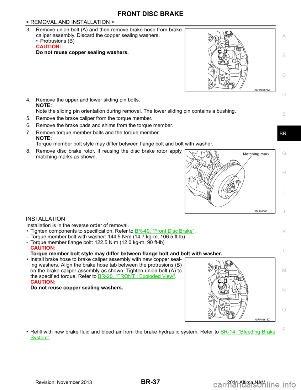
3. Remove union bolt (A) and then remove brake hose from brake caliper assembly. Discard the copper sealing washers.
• Protrusions (B)
CAUTION:
Do not reuse copper sealing washers.
4. Remove the upper and lower sliding pin bolts. NOTE:
Note the sliding pin orientation during removal. The lower sliding pin contains a bushing.
5. Remove the brake caliper from the torque member.
6. Remove the brake pads and shims from the torque member.
7. Remove torque member bolts and the torque member. NOTE:
Torque member bolt style may differ between flange bolt and bolt with washer.
8. Remove disc brake rotor. If reusing the disc brake rotor apply matching marks as shown.
INSTALLATION
Installation is in the reverse order of removal.
• Tighten components to specification. Refer to BR-49, "Front Disc Brake"
.
- Torque member bolt with washer: 144.5 N·m (14.7 kg-m, 106.5 ft-lb)
- Torque member flange bolt: 122.5 N·m (12.0 kg-m, 90 ft-lb) CAUTION:
Torque member bolt style may differ betw een flange bolt and bolt with washer.
• Install brake hose to brake caliper assembly with new copper seal- ing washers. Align the brake hos e tab between the protrusions (B)
on the brake caliper assembly as shown. Tighten union bolt (A) to
the specified torque. Refer to BR-20, "FRONT : Exploded View"
.
CAUTION:
Do not reuse copper sealing washers.
• Refill with new brake fluid and bleed air fr om the brake hydraulic system. Refer to BR-14, "Bleeding Brake
System".
ALFIA0287ZZ
SDIA2608E
ALFIA0287ZZ
Revision: November 20132014 Altima NAM
Page 136 of 4801

BR-40
< REMOVAL AND INSTALLATION >
REAR DISC BRAKE
BRAKE CALIPER ASSEMBLY : Removal and Installation
INFOID:0000000009463719
WARNING:
Clean dust on brake calipers and brake pads with a vacuum dust collector to minimize the hazard of
airborne particles or other materials.
CAUTION:
• While removing brake caliper, do not depr ess brake pedal because the piston will pop out.
• Do not damage piston boot.
• Keep disc brake rotor free from brake fluid.
• Refill the brake reservoir with new brake fluid “DOT 3”.
• Do not reuse drained brake fluid.
NOTE:
When removing components such as hoses, tubes/lines, etc. , cap or plug openings to prevent fluid from spill-
ing.
REMOVAL
1. Remove rear wheel and tire using power tool. Refer to WT-55, "Adjustment".
2. Remove reservoir cap.
3. Partially drain brake fluid from the master cylinder. Refer to BR-14, "Drain and Refill"
.
4. Remove union bolt (A) and then remove brake hose from brake caliper. Discard the copper sealing wash- ers.
CAUTION:
Do not reuse copp er sealing washers.
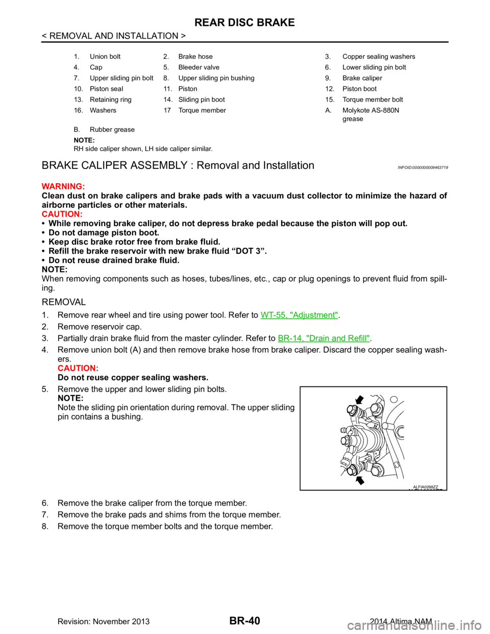
5. Remove the upper and lower sliding pin bolts. NOTE:
Note the sliding pin orientation during removal. The upper sliding
pin contains a bushing.
6. Remove the brake caliper from the torque member.
7. Remove the brake pads and shims from the torque member.
8. Remove the torque member bolts and the torque member.
1. Union bolt 2. Brake hose 3. Copper sealing washers
4. Cap 5. Bleeder valve 6. Lower sliding pin bolt
7. Upper sliding pin bolt 8. Upper sliding pin bushing 9. Brake caliper
10. Piston seal 11. Piston 12. Piston boot
13. Retaining ring 14. Sliding pin boot 15. Torque member bolt
16. Washers 17 Torque member A. Molykote AS-880N grease
B. Rubber grease
NOTE:
RH side caliper shown, LH side caliper similar.
ALFIA0288ZZ
Revision: November 20132014 Altima NAM
Page 137 of 4801

REAR DISC BRAKEBR-41
< REMOVAL AND INSTALLATION >
C
D E
G H
I
J
K L
M A
B
BR
N
O P
9. Remove the disc brake rotor. If reusing the disc brake rotor apply matching marks as shown.
INSTALLATION
Installation is in the reverse order of removal.
• Tighten components to specification. Refer to BR-39, "BRAKE CALIPER ASSEMBLY : Exploded View"
.
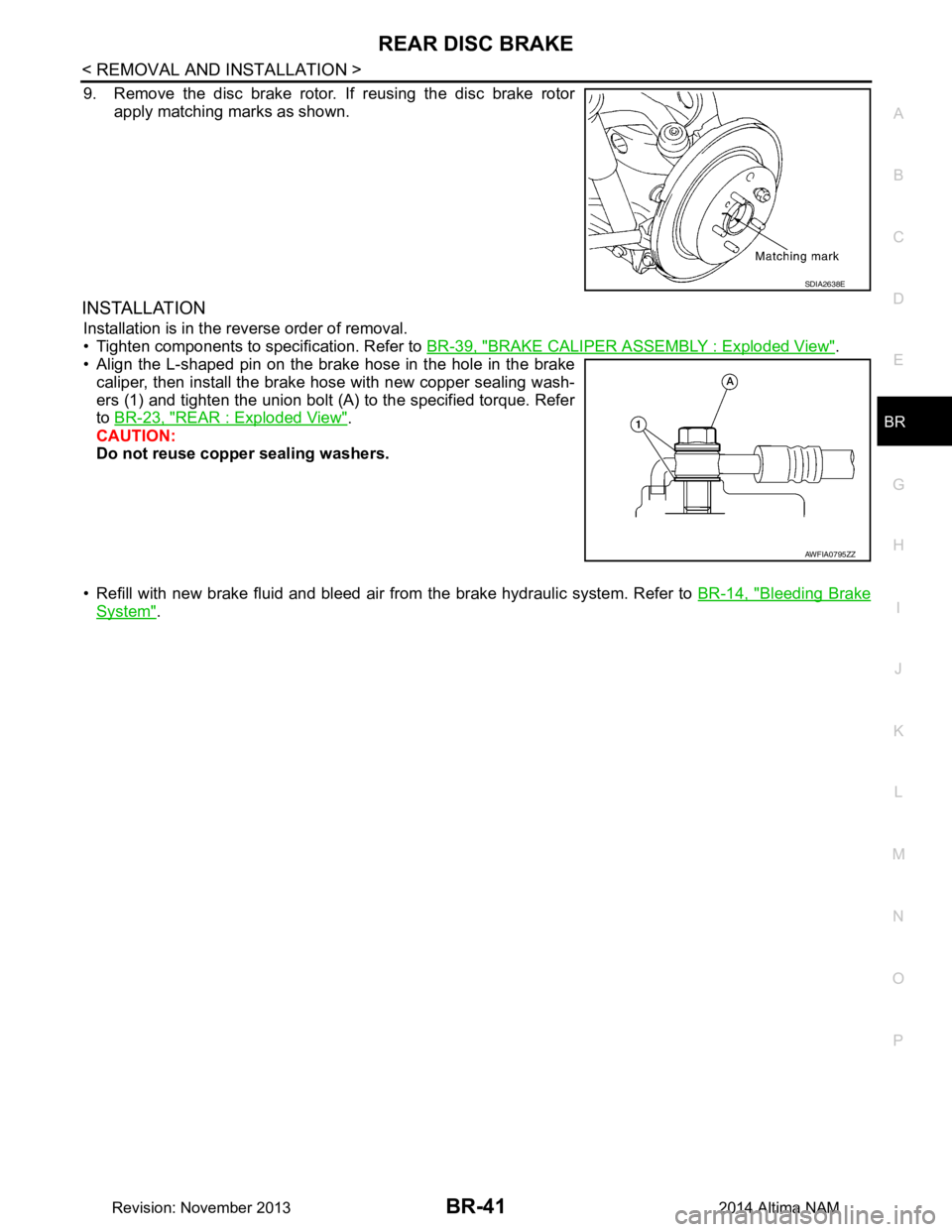
• Align the L-shaped pin on the brake hose in the hole in the brake
caliper, then install the brake hose with new copper sealing wash-
ers (1) and tighten the union bolt (A) to the specified torque. Refer
to BR-23, "REAR : Exploded View"
.
CAUTION:
Do not reuse copper sealing washers.
• Refill with new brake fluid and bleed air fr om the brake hydraulic system. Refer to BR-14, "Bleeding Brake
System".
SDIA2638E
AWFIA0795ZZ
Revision: November 20132014 Altima NAM