2014 NISSAN TEANA washer fluid
[x] Cancel search: washer fluidPage 3262 of 4801

MWI
COMPONENT PARTSMWI-7
< SYSTEM DESCRIPTION >
C
D E
F
G H
I
J
K L
M B
A
O P
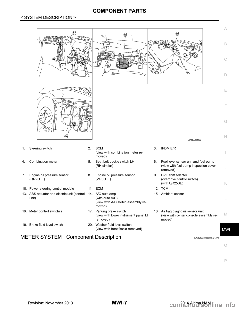
METER SYSTEM : Component DescriptionINFOID:0000000009461670
1. Steering switch 2. BCM (view with combination meter re-
moved) 3. IPDM E/R
4. Combination meter 5. Seat belt buckle switch LH (RH similar) 6. Fuel level sensor unit and fuel pump
(view with fuel pump inspection cover
removed)
7. Engine oil pressure sensor (QR25DE) 8. Engine oil pressure sensor
(VQ35DE) 9. CVT shift selector
(overdrive control switch)
(with QR25DE)
10. Power steering control module 11. ECM 12. TCM
13. ABS actuator and electric unit (control unit) 14. A/C auto amp
(with auto A/C)
(view with A/C swit ch assembly re-
moved) 15. Ambient sensor
16. Meter control switches 17. Parking brake switch (view with lower instrument panel LH
removed) 18. Air bag diagnosis sensor unit
(view with center console assembly re-
moved)
19. Brake fluid level switch 20. Washer fluid level switch (view with front fascia removed)
AWNIA2641ZZ
Revision: November 20132014 Altima NAMRevision: November 20132014 Altima NAM
Page 3263 of 4801

MWI-8
< SYSTEM DESCRIPTION >
COMPONENT PARTS
Unit Description
Combination meter Controls the following with the signals received from each unit via CAN communication and the signals
from switches and sensors:
• Speedometer
• Tachometer
• Engine coolant temperature gauge
• Fuel gauge
• Warning lamps
• Indicator lamps
• Meter illumination control
• Meter effect function
• Information display
Meter control switch Transmits the following signals to the combination meter:
• Trip reset switch signal
• Illumination control switch signal (+)
• Illumination control switch signal ( −)
ECM Transmits the following signals to the combination meter via CAN communication:
• Engine speed signal
• Engine coolant temperature signal
• Engine oil pressure warning signal
• Fuel consumption monitor signal
ABS actuator and electric unit
(control unit) Transmits the vehicle speed signal to the combination meter via CAN communication.
Power steering control module Transmits the EPS signal to the combination meter via CAN communication.
BCM Transmits the following signals to the combination meter via CAN communication:
• Tire pressure information
• Position light request signal
• Low tire pressure warning lamp signal
• Door switch signal
• Trunk lamp switch signal
TCM Receives the O/D OFF switch signal from the combination meter via CAN communication.
Transmits the O/D OFF indicator request signal to the combination meter via CAN communication.
CVT shift selector switch
(overdrive co ntrol switch)
(with QR25DE) Transmits the O/D OFF switch signal to the combination meter
Fuel level sensor unit Transmits the fuel level sensor signal to the combination meter.
Seat belt buckle switch LH
(RH similar) Transmits the seat belt buckle switch LH signal to the combination meter.
Air bag diagnosis sensor unit Transmits the following signals to the combination meter:
• Seat belt buckle switch RH signal
• Air bag warning indicator
Engine oil pressure sensor Transmits the engine oil pressure sensor signal to the ECM.
Ambient sensor Transmits the ambient sensor signal to the IPDM E/R.
A/C auto amp. • Receives the ambient sensor signal from the IPDM E/R (with auto A/C).
• Transmits the ambient sensor signal to the combination meter via CAN communication.
Parking brake switch Transmits the parking brake switch signal to the combination meter.
Washer fluid level switch Transmits the washer fluid level switch signal to the combination meter.
Steering switch Transmits the following signals to the information display:
• Display signal
• Menu up signal
• Menu down signal
• Enter signal
• Back signal
IPDM E/R • Receives the ambient sensor signal from the ambient sensor.
• Transmits the ambient sensor signal to the combination meter (without auto A/C).
• Transmits the ambient sensor signal to the A/C auto amp (with auto A/C).
Brake fluid level switch Transmits the brake fluid level switch signal to the combination meter.
Revision: November 20132014 Altima NAMRevision: November 20132014 Altima NAM
Page 3268 of 4801

MWI
SYSTEMMWI-13
< SYSTEM DESCRIPTION >
C
D E
F
G H
I
J
K L
M B
A
O P
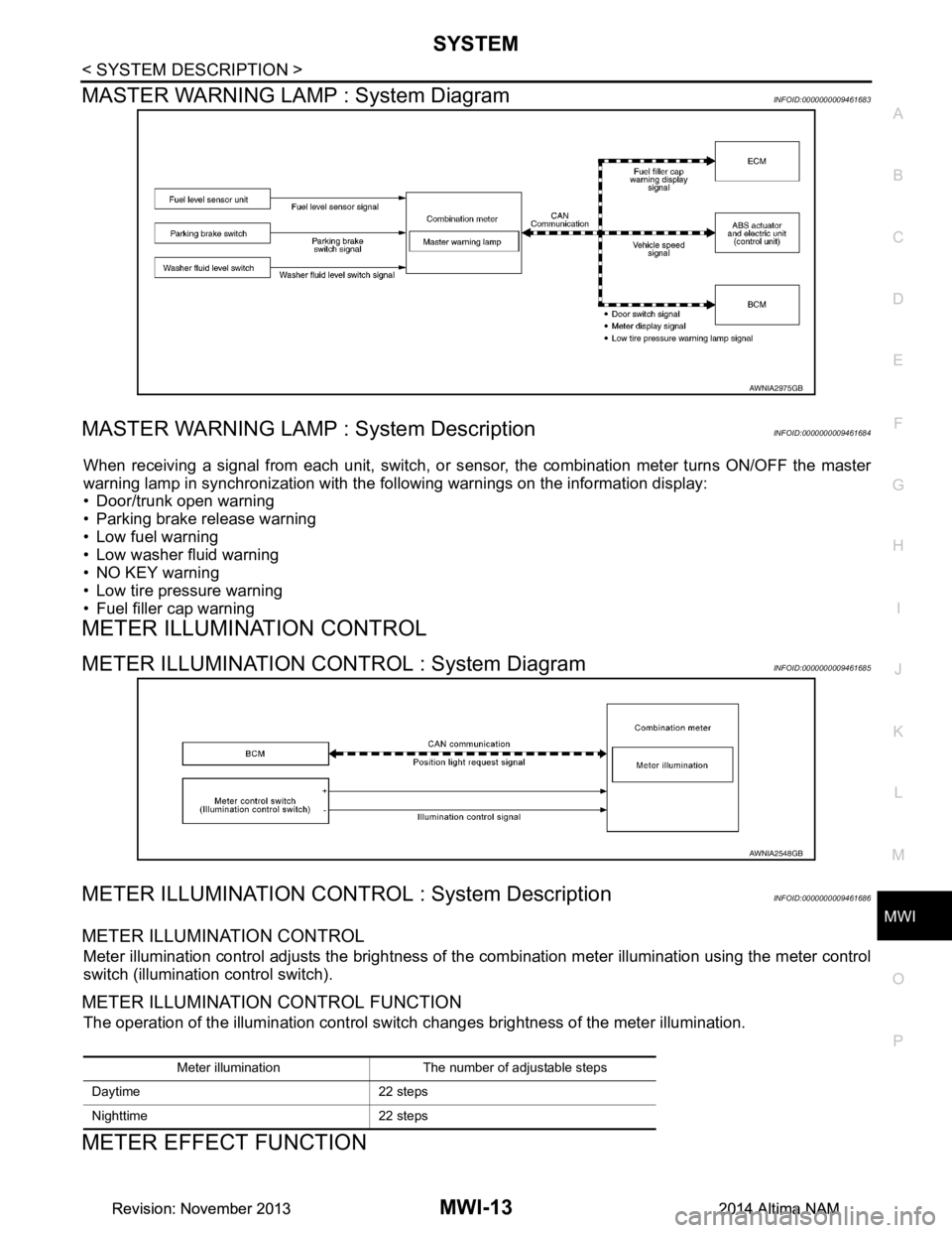
MASTER WARNING LAMP : System DiagramINFOID:0000000009461683
MASTER WARNING LAMP : System DescriptionINFOID:0000000009461684
When receiving a signal from each unit, switch, or s ensor, the combination meter turns ON/OFF the master
warning lamp in synchronization with the following warnings on the information display:
• Door/trunk open warning
• Parking brake release warning
• Low fuel warning
• Low washer fluid warning
• NO KEY warning
• Low tire pressure warning
• Fuel filler cap warning
METER ILLUMINATION CONTROL
METER ILLUMINATION CONTROL : System DiagramINFOID:0000000009461685
METER ILLUMINATION CONTROL : System DescriptionINFOID:0000000009461686
METER ILLUMINATION CONTROL
Meter illumination control adjusts the brightness of the combination meter illumination using the meter control
switch (illumination control switch).
METER ILLUMINATION CONTROL FUNCTION
The operation of the illumination control switch changes brightness of the meter illumination.
METER EFFECT FUNCTION
AWNIA2975GB
AWNIA2548GB
Meter illumination The number of adjustable steps
Daytime 22 steps
Nighttime 22 steps
Revision: November 20132014 Altima NAMRevision: November 20132014 Altima NAM
Page 3270 of 4801

MWI
SYSTEMMWI-15
< SYSTEM DESCRIPTION >
C
D E
F
G H
I
J
K L
M B
A
O P
Engine-start effect exits when any of the above operat ional conditions is cancelled during the engine-start
effect.
INFORMATION DISPLAY
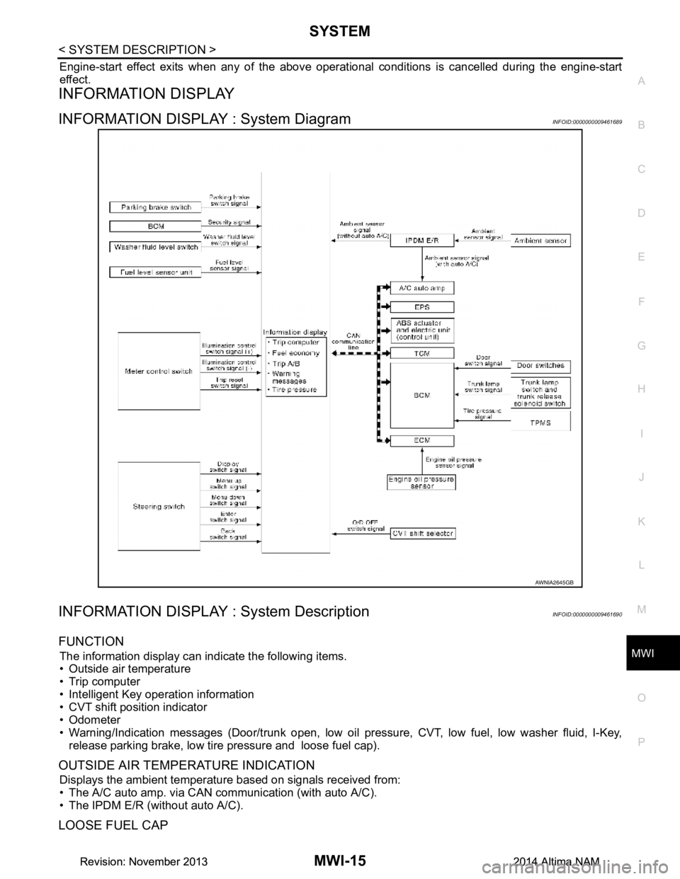
INFORMATION DISPLAY : System DiagramINFOID:0000000009461689
INFORMATION DISPLAY : System DescriptionINFOID:0000000009461690
FUNCTION
The information display can indicate the following items.
• Outside air temperature
• Trip computer
• Intelligent Key operation information
• CVT shift position indicator
• Odometer
• Warning/Indication messages (Door/trunk open, low oil pressure, CVT, low fuel, low washer fluid, I-Key,
release parking brake, low tire pressure and loose fuel cap).
OUTSIDE AIR TEMPERATURE INDICATION
Displays the ambient temperature based on signals received from:
• The A/C auto amp. via CAN communication (with auto A/C).
• The IPDM E/R (without auto A/C).
LOOSE FUEL CAP
AWNIA2645GB
Revision: November 20132014 Altima NAMRevision: November 20132014 Altima NAM
Page 3271 of 4801

MWI-16
< SYSTEM DESCRIPTION >
SYSTEM
The LOOSE FUEL CAP message will display in the information display when the fuel-filler cap is not tightened
correctly. The message will turn off as soon as the EC M detects the fuel-filler cap is properly tightened. The
ECM provides a loose fuel cap signal to the combination meter via CAN communication.
LOW TIRE PRESSURE WARNING
This warning appears when the BCM detects low inflati on pressure or a system malfunction. The BCM sends
a signal to the combination meter via CAN communication to illuminate the low tire pressure warning lamp. In
addition, a warning message will be displayed in the vehicle information display.
DOOR OPEN WARNING
This warning appears when the ignition switch is ON and the door is open. The BCM receives a door switch
signal from the door open door switch. The BCM sends t he door switch signal to the combination meter via
CAN communication lines.
TRUNK OPEN WARNING
This warning appears when the ignition switch is ON and the trunk is opened. The BCM receives a trunk lamp
switch signal from the trunk lamp switch. The BCM s ends the trunk lamp switch signal to the combination
meter via CAN communication.
LOW FUEL WARNING
This warning appears when the fuel level in the fuel tank is less than approximately 4 US gal (15 L, 3.3 Imp
gal). A variable resistor signal is supplied to the combi nation meter from the fuel level sensor unit to determine
the amount of fuel in the fuel tank.
LOW WINDSHIELD WASHER FLUID WARNING
When the windshield washer fluid level is low, the was her fluid level switch provides a ground signal to the
combination meter and the warning is displayed. Once fluid is added, the switch opens and the warning is no
longer displayed.
RELEASE PARKING BRAKE WARNING
When the parking brake is applied, the parking brake switch provides a ground signal to the combination
meter. When the vehicle speed is greater than 4 MPH (7 km/h), the message is displayed and the warning
chime sounds.
SHIFT POSITION INDICATOR
Displays the position of the shift selector based on signals received from TCM via CAN communication.
LOW OIL PRESSURE WARNING
The low oil pressure warning appears in the information display when the combination meter receives a low
engine oil pressure signal from the ECM via CAN communication.
WARNING CHECK INDICATION
The combination meter can cause an interrupt on the information display to indicate a warning, based on sig-
nals received from each unit and switch.
Refer to Owner’s Manual for additional information display items.
COMPASS
COMPASS : DescriptionINFOID:0000000009461691
DESCRIPTION
With the ignition switch in the ON position, and the mode (N) switch
ON, the compass display will indicate the direction the vehicle is
heading.
Vehicle direction is displayed as follows:
• N: north
• E: east
• S: south
•W: west
LKIA0447E
Revision: November 20132014 Altima NAMRevision: November 20132014 Altima NAM
Page 3275 of 4801
![NISSAN TEANA 2014 Service Manual
MWI-20
< SYSTEM DESCRIPTION >
DIAGNOSIS SYSTEM (METER)
FUEL W/L
[On/Off] Displays [ON/OFF] condition of low-fuel warning message.
WASHER W/L
[On/Off] Displays [ON/OFF] condition of low washer fluid NISSAN TEANA 2014 Service Manual
MWI-20
< SYSTEM DESCRIPTION >
DIAGNOSIS SYSTEM (METER)
FUEL W/L
[On/Off] Displays [ON/OFF] condition of low-fuel warning message.
WASHER W/L
[On/Off] Displays [ON/OFF] condition of low washer fluid](/manual-img/5/57390/w960_57390-3274.png)
MWI-20
< SYSTEM DESCRIPTION >
DIAGNOSIS SYSTEM (METER)
FUEL W/L
[On/Off] Displays [ON/OFF] condition of low-fuel warning message.
WASHER W/L
[On/Off] Displays [ON/OFF] condition of low washer fluid warning message.
AIR PRES W/L
[ON/OFF] Displays [ON/OFF] condition of tire pressure warning lamp.
KEY G/Y W/L
[On/Off] Displays [ON/OFF] condition of key green warning lamp.
EPS W/L
[On/Off] Displays [ON/OFF] condition of EPS warning indicator.
LCD Displays the value of Intelligent Key system message indication.
ACC SET SPEED
[Off, km/h or mph] Displays OFF or SET vehicle speed status in the information display.
ACC UNIT
[On/Off] Displays [ON/OFF] condition of display unit in the information display.
SHIFT IND
[P, R, N, D, DS] Displays [P, R, N, D, DS] shift selector position.
FUEL CAP W/L
[On/Off] Displays [ON/OFF] condition of loose fuel cap warning message.
O/D OFF SW
[ON/OFF] Displays [ON/OFF] condition of O/D OFF switch.
M RANGE SW
[On/Off] Displays [ON/OFF] condition of manual mode switch.
NM RANGE SW
[On/Off] Displays [ON/OFF] condition of non-manual mode switch.
AT SFT UP SW
[On/Off] Displays [ON/OFF] condition of manual mode shift up switch.
AT SFT DWN SW
[On/Off] Displays [ON/OFF] condition of manual mode shift down switch.
ST SFT UP SW
[On/Off] Displays [ON/OFF] condition of paddle shift up switch.
ST SFT DWN SW
[On/Off] Displays [ON/OFF] condition of paddle shift down switch.
PKB SW
[On/Off] Displays [ON/OFF] condition of parking brake switch.
BUCKLE SW
[ON/OFF] Status of seat belt buckle switch (LH).
BRAKE OIL SW
[On/Off] Displays [ON/OFF] condition of brake fluid level switch.
PASS BUCKLE SW
[ON/OFF] Status of passenger seat belt buckle switch (RH).
DISTANCE
[Mi] or [km] Displays distance to empty.
OUTSIDE TEMP
[ ° F or °C] Displaysthe ambient air temperature which is input from the ambient sensor.
FUEL LOW SIG
[On/Off] Displays [ON/OFF] condition
of low-fuel warning signal.
BUZZER
[On/Off] XBuzzer status (in the combination meter) is detected from the buzzer output signal
received from each unit via CAN communication and the warning output condition
of the combination meter.
BSW IND
[ON/OFF] Displays [ON/OFF] condition of BSW warning indicator message in the informa-
tion display.
Display item [Unit]
MAIN
SIGNALS Description
Revision: November 20132014 Altima NAMRevision: November 20132014 Altima NAM
Page 3278 of 4801

MWI
COMBINATION METERMWI-23
< ECU DIAGNOSIS INFORMATION >
C
D E
F
G H
I
J
K L
M B
A
O P
CRUISE W/L Ignition switch ON CRUISE warning indication On
CRUISE warning indication Off
CVT IND Ignition switch ON CVT indicator ON On
CVT indicator OFF Off
SET IND Ignition switch ON SET indicator ON On
SET indicator OFF Off
FUEL LOW SIG Ignition switch ON During low fuel level indication On
Except during low fuel level indication Off
O/D OFF IND Ignition switch ON O/D OFF indicator ON On
O/D OFF indicator OFF Off
FUEL W/L Ignition switch ON During low fuel level indication On
Except during low fuel level indication Off
WASHER W/L Ignition switch ON Low washer fluid warning indication On
Except during low washer fluid warning in-
dication Off
AIR PRES W/L Tire pressure warn-
ing lamp operation When tire pressure
warning lamp is ON On
When tire pressure wa rning lamp is OFF Off
KEY G/Y W/L Ignition switch ON During Intelligent Key system malfunction
indication On
Other than the above Off
EPS W/L Ignition switch ON EPS warning lamp ON On
EPS warning lamp OFF Off
LCD Ignition switch ACC During engine start information indication B&P
ACC SET SPEED Ignition switch ON During set vehicle speed indicator not dis-
played Off
During set vehicle speed indicator dis-
played Indicates the set vehicle speed
ACC UNIT Ignition switch ON Set vehicle speed indicator unit display ON On
Set vehicle speed indicator unit display
OFF Off
SHIFT IND Ignition switch ON Position of shift selector [P, R, N, D, DS]
FUEL CAP W/L Ignition switch ON Fuel filler cap warning display ON On
Fuel filler cap warning display OFF Off
O/D OFF SW Ignition switch ON Overdrive control switch ON On
Overdrive control switch OFF Off
M RANGE SW Ignition switch ON Shift selector in manual mode position On
Other than the above Off
NM RANGE SW Ignition switch ON Shift selector in manual mode position Off
Other than the above On
AT SFT UP SW Ignition switch ON Shift selector operated in the up position On
Other than the above Off
AT SFT DWN SW Ignition switch ON Shift selector operated in the down position On
Other than the above Off
ST SFT UP SW Ignition switch ON Paddle shifter operated in up position On
Shift selector is in non manual mode up
position Off
Monitor Item Condition Value/Status
Revision: November 20132014 Altima NAMRevision: November 20132014 Altima NAM
Page 3281 of 4801

MWI-26
< ECU DIAGNOSIS INFORMATION >
COMBINATION METER
31
(W) Ground Ambient sensor ground
(without auto A/C) InputIgnition
switch
ON —0 V
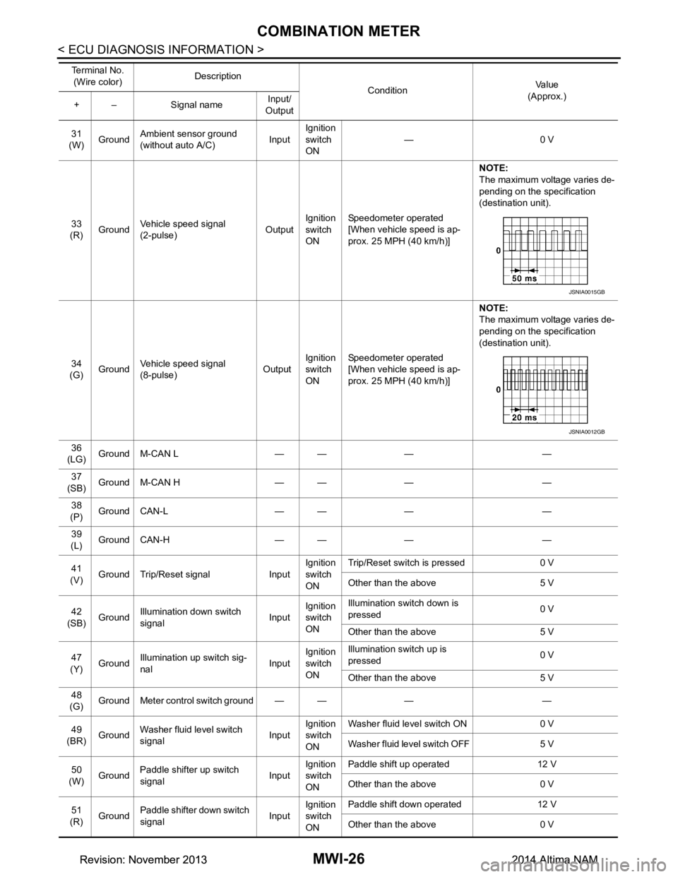
33
(R) Ground Vehicle speed signal
(2-pulse) OutputIgnition
switch
ON Speedometer operated
[When vehicle speed is ap-
prox. 25 MPH (40 km/h)] NOTE:
The maximum voltage varies de-
pending on the specification
(destination unit).
34
(G) Ground Vehicle speed signal
(8-pulse) OutputIgnition
switch
ON Speedometer operated
[When vehicle speed is ap-
prox. 25 MPH (40 km/h)] NOTE:
The maximum voltage varies de-
pending on the specification
(destination unit).
36
(LG) Ground M-CAN L — — — —
37
(SB) Ground M-CAN H — — — —
38
(P) Ground CAN-L — — — —
39
(L) Ground CAN-H — — — —
41
(V) Ground Trip/Reset signal Input Ignition
switch
ON Trip/Reset switch is pressed 0 V
Other than the above 5 V
42
(SB) Ground Illumination down switch
signal InputIgnition
switch
ON Illumination switch down is
pressed 0 V
Other than the above 5 V
47
(Y) Ground
Illumination up switch sig-
nal InputIgnition
switch
ON Illumination switch up is
pressed 0 V
Other than the above 5 V
48
(G) Ground Meter control switch ground — — — —
49
(BR) Ground Washer fluid level switch
signal InputIgnition
switch
ON Washer fluid level switch ON 0 V
Washer fluid level switch OFF 5 V
50
(W) Ground
Paddle shifter up switch
signal InputIgnition
switch
ON Paddle shift up operated 12 V
Other than the above 0 V
51
(R) Ground Paddle shifter down switch
signal InputIgnition
switch
ON Paddle shift down operated 12 V
Other than the above 0 V
Te r m i n a l N o .
(Wire color) Description
ConditionVa l u e
(Approx.)
+ – Signal name Input/
Output
JSNIA0015GB
JSNIA0012GB
Revision: November 20132014 Altima NAMRevision: November 20132014 Altima NAM