2014 NISSAN TEANA washer fluid
[x] Cancel search: washer fluidPage 4606 of 4801
![NISSAN TEANA 2014 Service Manual
CONTROL VALVETM-391
< REMOVAL AND INSTALLATION > [CVT: RE0F10E]
C
EF
G H
I
J
K L
M A
B
TM
N
O P
5. Connect the control valve harness connectors (A).
CAUTION:
• Do not pinch the harness be tween t NISSAN TEANA 2014 Service Manual
CONTROL VALVETM-391
< REMOVAL AND INSTALLATION > [CVT: RE0F10E]
C
EF
G H
I
J
K L
M A
B
TM
N
O P
5. Connect the control valve harness connectors (A).
CAUTION:
• Do not pinch the harness be tween t](/manual-img/5/57390/w960_57390-4605.png)
CONTROL VALVETM-391
< REMOVAL AND INSTALLATION > [CVT: RE0F10E]
C
EF
G H
I
J
K L
M A
B
TM
N
O P
5. Connect the control valve harness connectors (A).
CAUTION:
• Do not pinch the harness be tween the control valve and
the transaxle case.
• Securely insert the harness connector until it clicks and
locks.
6. Install CVT fluid temperature sensor bracket (1).
7. Install the bracket (1).
8. Install O-ring to oil strainer assembly. CAUTION:
• Do not reuse O-ring.
• Apply CVT fluid NS-3 to O-ring.
9. Install the oil strainer assembly (1) using the oil strainer assem- bly bolts (A) and (B).
NOTE:
Remove the bracket and adjust the position again if the bolt hole
positions are not aligned.
10. Install the manual plate (1) while aligning with the groove (A) of the manual valve.
CAUTION:
Assemble the manual plate whil e aligning its end with the
cutout ( ) of the manual valve.
11. Install the spring washer (2) and the lock-nut (3), and then tighten to the specified torque.
: Front
: Bolt
JSDIA3686ZZ
: Bolt
: Front
JPDIA0658ZZ
: Front
Bolt Bolt length (mm) Number of bolts A12 2
B44 1
(A) : Manual shaft : Front
JPDIA0657ZZ
JPDIA0962ZZ
Revision: November 20132014 Altima NAMRevision: November 20132014 Altima NAM
Page 4623 of 4801
![NISSAN TEANA 2014 Service Manual
TM-408
< UNIT REMOVAL AND INSTALLATION >[CVT: RE0F10E]
TRANSAXLE ASSEMBLY
1. Remove the engine and transaxle with the front suspension member as a unit. Refer to
EM-220,
"Removal and Installation".
NISSAN TEANA 2014 Service Manual
TM-408
< UNIT REMOVAL AND INSTALLATION >[CVT: RE0F10E]
TRANSAXLE ASSEMBLY
1. Remove the engine and transaxle with the front suspension member as a unit. Refer to
EM-220,
"Removal and Installation".](/manual-img/5/57390/w960_57390-4622.png)
TM-408
< UNIT REMOVAL AND INSTALLATION >[CVT: RE0F10E]
TRANSAXLE ASSEMBLY
1. Remove the engine and transaxle with the front suspension member as a unit. Refer to
EM-220,
"Removal and Installation".
2. Disconnect the transaxle harness connectors.
3. Disconnect the CVT oil warmer water hoses from engine side. Refer to TM-400, "WATER HOSE :
Removal and Installation".
4. Remove the CVT fluid charging pipe.
5. Remove the transaxle to engine and engine to transaxle bolts.
6. Separate the engine from the transaxle and remove the engine from the front suspension member. Refer to EM-220, "Removal and Installation"
.
NOTE:
Using paint, put matching marks on the drive plat e and torque converter when removing the torque con-
verter to drive plate nuts.
7. Remove transmission bracket.
8. Lift the transaxle from the front suspension member.
INSTALLATION
Installation is in the reverse order of removal.
NOTE:
Write down the serial number of the new transaxle assembly.
CAUTION:
• When replacing an engine or transaxle you must m ake sure any dowels are installed correctly during
re-assembly
• Improper alignment caused by missing dowels m ay cause vibration, oil leaks or breakage of drive
train components.
• Do not reuse O-rings or copper sealing washers.
• When turning crankshaft, turn it clockwi se as viewed from the front of the engine.
• When tightening the nuts for the torque converte r while securing the crankshaft pulley bolt, be sure
to confirm the tightening torque of the crankshaft pulley bolt. Refer to EM-174, "Removal and Instal-
lation".
• After converter is installed to drive plate, rota te crankshaft several turns to check that CVT rotates
freely without binding.
• When installing the CVT to the en gine, align the matching mark on the drive plate with the matching
mark on the torque converter.
When installing CVT assembly to th e engine assembly, attach the bolts in accordance with the follow-
ing standard.
JSDIA4208GB
Revision: November 20132014 Altima NAMRevision: November 20132014 Altima NAM
Page 4653 of 4801
![NISSAN TEANA 2014 Service Manual
WCS
DIAGNOSIS SYSTEM (METER)WCS-11
< SYSTEM DESCRIPTION >
C
D E
F
G H
I
J
K L
M B
A
O P
FUEL W/L
[On/Off] Displays [ON/OFF] condition of low-fuel warning message.
WASHER W/L
[On/Off] Displays [ON/ NISSAN TEANA 2014 Service Manual
WCS
DIAGNOSIS SYSTEM (METER)WCS-11
< SYSTEM DESCRIPTION >
C
D E
F
G H
I
J
K L
M B
A
O P
FUEL W/L
[On/Off] Displays [ON/OFF] condition of low-fuel warning message.
WASHER W/L
[On/Off] Displays [ON/](/manual-img/5/57390/w960_57390-4652.png)
WCS
DIAGNOSIS SYSTEM (METER)WCS-11
< SYSTEM DESCRIPTION >
C
D E
F
G H
I
J
K L
M B
A
O P
FUEL W/L
[On/Off] Displays [ON/OFF] condition of low-fuel warning message.
WASHER W/L
[On/Off] Displays [ON/OFF] condition of low washer fluid warning message.
AIR PRES W/L
[ON/OFF] Displays [ON/OFF] condition of tire pressure warning lamp.
KEY G/Y W/L
[On/Off] Displays [ON/OFF] condition of key green warning lamp.
EPS W/L
[On/Off] Displays [ON/OFF] condition of EPS warning indicator.
LCD Displays the value of Intelligent Key system message indication.
ACC SET SPEED
[Off, km/h or mph] Displays OFF or SET vehicle speed status in the information display.
ACC UNIT
[On/Off] Displays [ON/OFF] condition of display unit in the information display.
SHIFT IND
[P, R, N, D, DS] Displays [P, R, N, D, DS] shift selector position.
FUEL CAP W/L
[On/Off] Displays [ON/OFF] condition of loose fuel cap warning message.
O/D OFF SW
[ON/OFF] Displays [ON/OFF] condition of O/D OFF switch.
M RANGE SW
[On/Off] Displays [ON/OFF] condition of manual mode switch.
NM RANGE SW
[On/Off] Displays [ON/OFF] condition of non-manual mode switch.
AT SFT UP SW
[On/Off] Displays [ON/OFF] condition of manual mode shift up switch.
AT SFT DWN SW
[On/Off] Displays [ON/OFF] condition of manual mode shift down switch.
ST SFT UP SW
[On/Off] Displays [ON/OFF] condition of paddle shift up switch.
ST SFT DWN SW
[On/Off] Displays [ON/OFF] condition of paddle shift down switch.
PKB SW
[On/Off] Displays [ON/OFF] condition of parking brake switch.
BUCKLE SW
[ON/OFF] Status of seat belt buckle switch (LH).
BRAKE OIL SW
[On/Off] Displays [ON/OFF] condition of brake fluid level switch.
PASS BUCKLE SW
[ON/OFF] Status of passenger seat belt buckle switch (RH).
DISTANCE
[Mi] or [km] Displays distance to empty.
OUTSIDE TEMP
[ ° F or °C] Displaysthe ambient air temperature which is input from the ambient sensor.
FUEL LOW SIG
[On/Off] Displays [ON/OFF] condition of low-fuel warning signal.
BUZZER
[On/Off] XBuzzer status (in the combination meter) is detected from the buzzer output signal
received from each unit via CAN communication and the warning output condition
of the combination meter.
BSW IND
[ON/OFF] Displays [ON/OFF] condition of BSW warning indicator message in the informa-
tion display.
Display item [Unit]
MAIN
SIGNALS Description
Revision: November 20132014 Altima NAMRevision: November 20132014 Altima NAM
Page 4740 of 4801
FRONT WIPER AND WASHER SYSTEMWW-5
< SYSTEM DESCRIPTION >
C
D E
F
G H
I
J
K
M A
B
WW
N
O P
*: For models with rear camera washer system
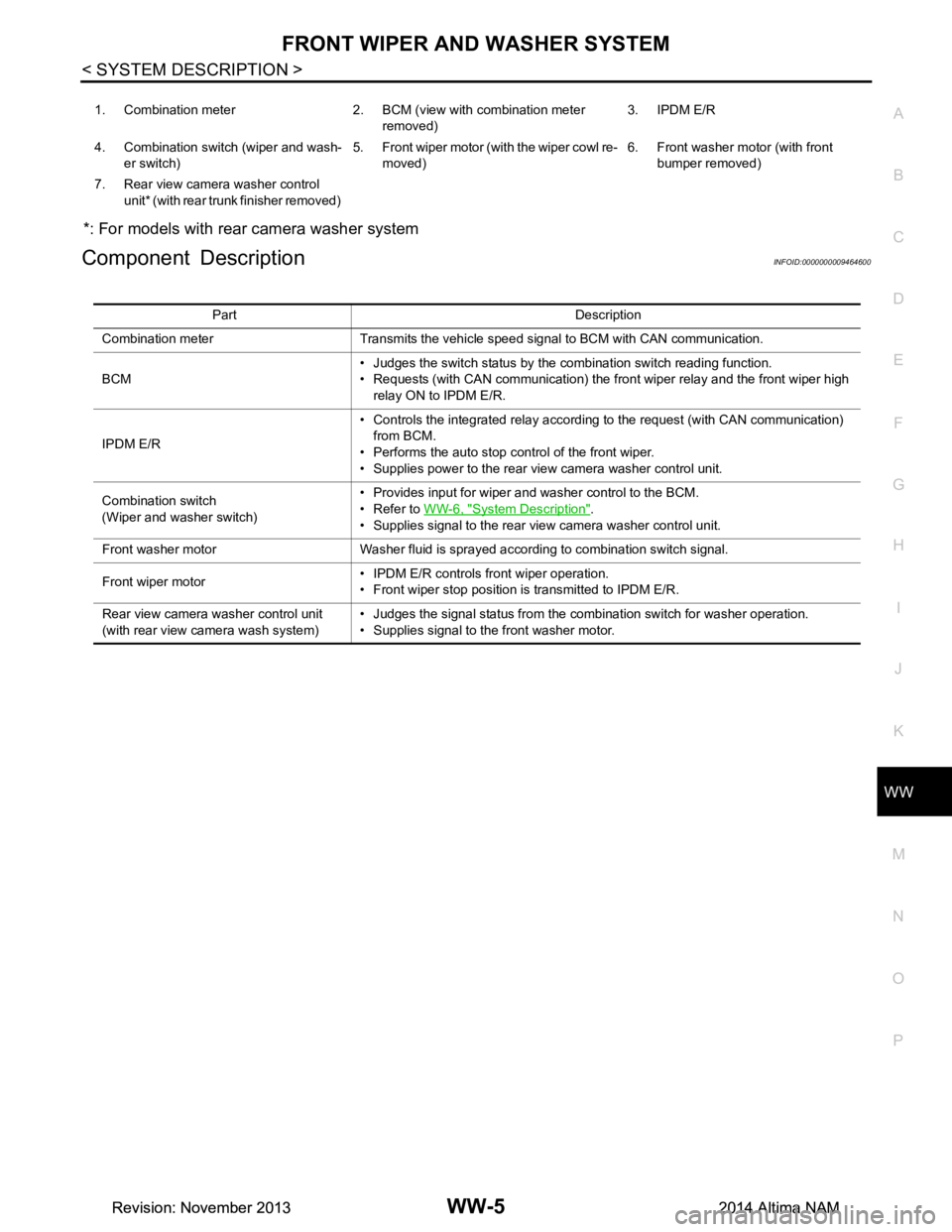
Component DescriptionINFOID:0000000009464600
1. Combination meter 2. BCM (v iew with combination meter
removed) 3. IPDM E/R
4. Combination switch (wiper and wash- er switch) 5. Front wiper motor (with the wiper cowl re-
moved) 6. Front washer motor (with front
bumper removed)
7. Rear view camera washer control unit* (with rear trunk finisher removed)
Part Description
Combination meter Transmits the vehicle speed signal to BCM with CAN communication.
BCM • Judges the switch status by the combination switch reading function.
• Requests (with CAN communication) the front wiper relay and the front wiper high
relay ON to IPDM E/R.
IPDM E/R • Controls the integrated relay according to the request (with CAN communication)
from BCM.
• Performs the auto stop control of the front wiper.
• Supplies power to the rear view camera washer control unit.
Combination switch
(Wiper and washer switch) • Provides input for wiper and washer control to the BCM.
• Refer to WW-6, "System Description"
.
• Supplies signal to the rear view camera washer control unit.
Front washer motor Washer fluid is sprayed according to combination switch signal.
Front wiper motor • IPDM E/R controls front wiper operation.
• Front wiper stop position is transmitted to IPDM E/R.
Rear view camera washer control unit
(with rear view ca mera wash system) • Judges the signal status from the combination switch for washer operation.
• Supplies signal to the front washer motor.
Revision: November 20132014 Altima NAMRevision: November 20132014 Altima NAM
Page 4786 of 4801
WASHER TANKWW-51
< REMOVAL AND INSTALLATION >
C
D E
F
G H
I
J
K
M A
B
WW
N
O P
REMOVAL AND INSTALLATION
WASHER TANK
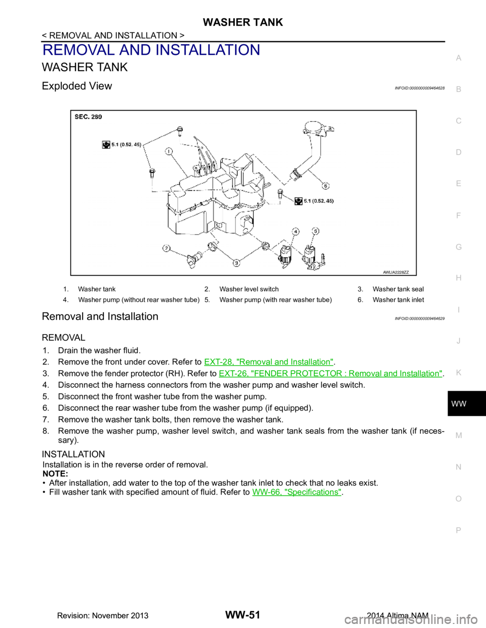
Exploded ViewINFOID:0000000009464628
Removal and InstallationINFOID:0000000009464629
REMOVAL
1. Drain the washer fluid.
2. Remove the front under cover. Refer to EXT-28, "Removal and Installation"
.
3. Remove the fender protector (RH). Refer to EXT-26, "FENDER PROTECTOR : Removal and Installation"
.
4. Disconnect the harness connectors from the washer pump and washer level switch.
5. Disconnect the front washer tube from the washer pump.
6. Disconnect the rear washer tube from the washer pump (if equipped).
7. Remove the washer tank bolts, then remove the washer tank.
8. Remove the washer pump, washer level switch, and wa sher tank seals from the washer tank (if neces-
sary).
INSTALLATION
Installation is in the reverse order of removal.
NOTE:
• After installation, add water to the top of the washer tank inlet to check that no leaks exist.
• Fill washer tank with specified amount of fluid. Refer to WW-66, "Specifications"
.
1. Washer tank 2. Washer level switch 3. Washer tank seal
4. Washer pump (without rear washer tube) 5. Washer pump (with rear washer tube) 6. Washer tank inlet
AWLIA2228ZZ
Revision: November 20132014 Altima NAMRevision: November 20132014 Altima NAM
Page 4787 of 4801
WW-52
< REMOVAL AND INSTALLATION >
WASHER PUMP
WASHER PUMP
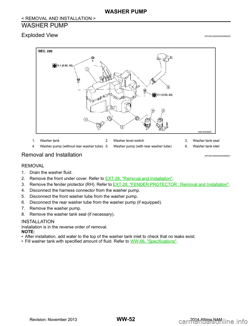
Exploded ViewINFOID:0000000009464630
Removal and InstallationINFOID:0000000009464631
REMOVAL
1. Drain the washer fluid.
2. Remove the front under cover. Refer to EXT-28, "Removal and Installation"
.
3. Remove the fender protector (RH). Refer to EXT-26, "FENDER PROTECTOR : Removal and Installation"
.
4. Disconnect the harness connecto r from the washer pump.
5. Disconnect the front washer tube from the washer pump.
6. Disconnect the rear washer tube from the washer pump (if equipped).
7. Remove the washer pump.
8. Remove the washer tank seal (if necessary).
INSTALLATION
Installation is in the reverse order of removal.
NOTE:
• After installation, add water to the top of the washer tank inlet to check that no leaks exist.
• Fill washer tank with specified amount of fluid. Refer to WW-66, "Specifications"
.
1. Washer tank 2. Washer level switch 3. Washer tank seal
4. Washer pump (without rear washer tube) 5. Washer pump (with rear washer tube) 6. Washer tank inlet
AWLIA2228ZZ
Revision: November 20132014 Altima NAMRevision: November 20132014 Altima NAM
Page 4788 of 4801
WASHER LEVEL SWITCHWW-53
< REMOVAL AND INSTALLATION >
C
D E
F
G H
I
J
K
M A
B
WW
N
O P
WASHER LEVEL SWITCH
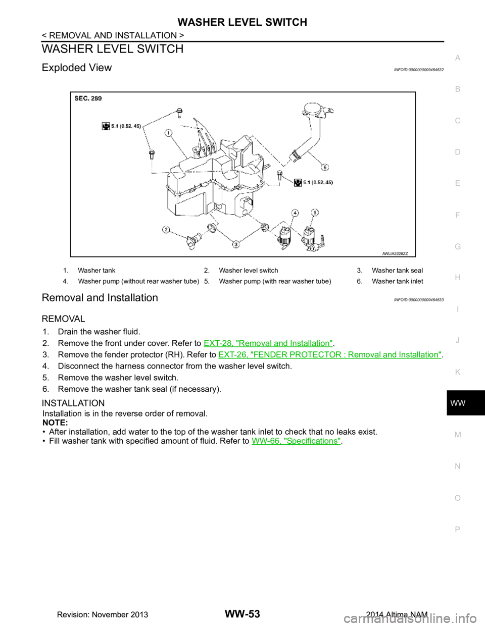
Exploded ViewINFOID:0000000009464632
Removal and InstallationINFOID:0000000009464633
REMOVAL
1. Drain the washer fluid.
2. Remove the front under cover. Refer to EXT-28, "Removal and Installation"
.
3. Remove the fender protector (RH). Refer to EXT-26, "FENDER PROTECTOR : Removal and Installation"
.
4. Disconnect the harness connector from the washer level switch.
5. Remove the washer level switch.
6. Remove the washer tank seal (if necessary).
INSTALLATION
Installation is in the reverse order of removal.
NOTE:
• After installation, add water to the top of the washer tank inlet to check that no leaks exist.
• Fill washer tank with specified amount of fluid. Refer to WW-66, "Specifications"
.
1. Washer tank 2. Washer level switch 3. Washer tank seal
4. Washer pump (without rear washer tube) 5. Washer pump (with rear washer tube) 6. Washer tank inlet
AWLIA2228ZZ
Revision: November 20132014 Altima NAMRevision: November 20132014 Altima NAM
Page 4791 of 4801
WW-56
< REMOVAL AND INSTALLATION >
WASHER NOZZLE & TUBE
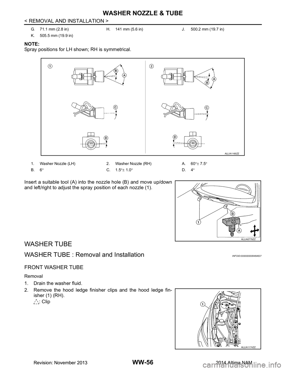
NOTE:
Spray positions for LH shown; RH is symmetrical.
Insert a suitable tool (A) into the nozzle hole (B) and move up/down
and left/right to adjust the spray position of each nozzle (1).
WASHER TUBE
WASHER TUBE : Removal and InstallationINFOID:0000000009464637
FRONT WASHER TUBE
Removal
1. Drain the washer fluid.
2. Remove the hood ledge finisher clips and the hood ledge fin- isher (1) (RH).
: Clip
G. 71.1 mm (2.8 in) H. 141 mm (5.6 in) J. 500.2 mm (19.7 in)
K. 505.5 mm (19.9 in)
1. Washer Nozzle (LH) 2. Washer Nozzle (RH) A. 60°± 7.5 °
B. 6 ° C. 1.5°± 1.0 ° D. 4°
ALLIA1165ZZ
ALLIA0779ZZ
ALLIA1174ZZ
Revision: November 20132014 Altima NAMRevision: November 20132014 Altima NAM