2014 NISSAN TEANA fuses
[x] Cancel search: fusesPage 753 of 4801

DEF-28
< DTC/CIRCUIT DIAGNOSIS >
REAR WINDOW DEFOGGER POWER SUPPLY AND GROUND CIRCUIT
REAR WINDOW DEFOGGER POWER SUPPLY AND GROUND CIRCUIT
DescriptionINFOID:0000000009463041
Heats the heating wire with the power supply from the rear window defogger relay to prevent the rear window
from fogging up.
Component Function CheckINFOID:0000000009463042
1. CHECK REAR WINDOW DEFOGGER
Check that the heating wire of rear window defogger is heated when turning the rear window defogger switch
ON.
Is the inspection result normal?
YES >> Rear window defogger is OK.
NO >> Refer to DEF-28, "Diagnosis Procedure"
.
Diagnosis ProcedureINFOID:0000000009463043
Regarding Wiring Diagram information, refer to DEF-11, "Wiring Diagram".
1. CHECK FUSES
Check if any of the following fuses in fuse block (J/B) are blown.
Is the inspection result normal?
YES >> GO TO 2.
NO >> Replace the blown fuse after repairing the affected circuit.
2. CHECK REAR WINDOW DEFOGGER POWER SUPPLY CIRCUIT
1. Turn ignition switch ON.
2. Check voltage between fuse block (J/B) connector and ground.
Is the inspection result normal?
YES >> GO TO 3.
NO >> Perform rear window defogger diagnosis. Refer to DEF-26, "Diagnosis Procedure"
.
3. CHECK POWER SUPPLY CIRCUIT
1. Turn ignition switch ON.
2. Check voltage between rear window defogger connector and ground.
COMPONENT PARTS AMPERE FUSE NO.
Fuse block (J/B) 15A 23
15A 24
(+) (–) Condition Voltage (V)
(Approx.)
Fuse block (J/B)
Connector Terminal
B13 3T, 5T Ground Rear window de-
fogger switch ON Battery voltage
OFF 0
Revision: November 20132014 Altima NAMRevision: November 20132014 Altima NAM
Page 1709 of 4801
![NISSAN TEANA 2014 Service Manual
POWER SUPPLY AND GROUND CIRCUITEC-709
< DTC/CIRCUIT DIAGNOSIS > [VQ35DE]
C
D E
F
G H
I
J
K L
M A
EC
NP
O
POWER SUPPLY AND GROUND CIRCUIT
Diagnosis ProcedureINFOID:0000000009462573
1.CHECK FUSE
Check NISSAN TEANA 2014 Service Manual
POWER SUPPLY AND GROUND CIRCUITEC-709
< DTC/CIRCUIT DIAGNOSIS > [VQ35DE]
C
D E
F
G H
I
J
K L
M A
EC
NP
O
POWER SUPPLY AND GROUND CIRCUIT
Diagnosis ProcedureINFOID:0000000009462573
1.CHECK FUSE
Check](/manual-img/5/57390/w960_57390-1708.png)
POWER SUPPLY AND GROUND CIRCUITEC-709
< DTC/CIRCUIT DIAGNOSIS > [VQ35DE]
C
D E
F
G H
I
J
K L
M A
EC
NP
O
POWER SUPPLY AND GROUND CIRCUIT
Diagnosis ProcedureINFOID:0000000009462573
1.CHECK FUSE
Check that there is no blowout in the following fuses.
Is the fuse fusing?
YES >> Replace the fuse after repairing the applicable circuit.
NO >> GO TO 2.
2.CHECK GROUND CONNECTION
1. Turn ignition switch OFF.
2. Check ground connection E9. Refer to GI-46, "Circuit Inspection"
.
Is the inspection result normal?
YES >> GO TO 3.
NO >> Repair or replace ground connection.
3.CHECK ECM GROUND CIRCUIT
1. Disconnect ECM harness connectors.
2. Check the continuity between ECM harness connector and ground.
Is the inspection result normal?
YES >> GO TO 4.
NO >> Repair or replace error-detected parts.
4.CHECK ECM POWER SUPPLY (MAIN)-I
1. Reconnect ECM harness connector.
2. Turn ignition switch ON.
3. Check the voltage between ECM harness connector terminals.
Is the inspection result normal?
YES >> GO TO 6.
NO >> GO TO 5.
5.CHECK ECM POWER SUPPLY (MAIN) CIRCUIT
Location Fuse No. Capacity
IPDM E/R #38 10 A
#45 10 A
+ −Continuity
ECM
Connector Terminal
F78 12
Ground Existed
16
E32 123
124
127
128
ECM Vo l ta g e
Connector +
−
Te r m i n a l
E32 121 128 Battery voltage
Revision: November 20132014 Altima NAMRevision: November 20132014 Altima NAM
Page 2357 of 4801

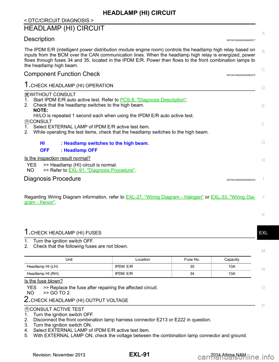
HEADLAMP (HI) CIRCUITEXL-91
< DTC/CIRCUIT DIAGNOSIS >
C
D E
F
G H
I
J
K
M A
B
EXL
N
O P
HEADLAMP (HI) CIRCUIT
DescriptionINFOID:0000000009463577
The IPDM E/R (intelligent power distribution modul e engine room) controls the headlamp high relay based on
inputs from the BCM over the CAN communication li nes. When the headlamp high relay is energized, power
flows through fuses 34 and 35, located in the IPDM E/R. Power then flows to the front combination lamps to
the headlamp high beam.
Component Function CheckINFOID:0000000009463578
1.CHECK HEADLAMP (HI) OPERATION
WITHOUT CONSULT
1. Start IPDM E/R auto active test. Refer to PCS-8, "Diagnosis Description"
.
2. Check that the headlamp switches to the high beam. NOTE:
HI/LO is repeated 1 second each when using the IPDM E/R auto active test.
CONSULT
1. Select EXTERNAL LAMP of IP DM E/R active test item.
2. While operating the test items, check t hat the headlamp switches to the high beam.
Is the inspection result normal?
YES >> Headlamp (HI) circuit is normal.
NO >> Refer to EXL-91, "Diagnosis Procedure"
.
Diagnosis ProcedureINFOID:0000000009463579
Regarding Wiring Diagram information, refer to EXL-27, "Wiring Diagram - Halogen" or EXL-33, "Wiring Dia-
gram - Xenon".
1.CHECK HEADLAMP (HI) FUSES
1. Turn the ignition switch OFF.
2. Check that the following fuses are not blown.
Is the fuse blown?
YES >> Replace the fuse after repairing the affected circuit.
NO >> GO TO 2.
2.CHECK HEADLAMP (HI) OUTPUT VOLTAGE
CONSULT ACTIVE TEST
1. Turn the ignition switch OFF.
2. Disconnect the front combination lamp harness connector E213 or E222 in question.
3. Turn the ignition switch ON.
4. Select EXTERNAL LAMP of IP DM E/R active test item.
5. With EXTERNAL LAMP ON, check the voltage between the combination lamp connector and ground.
HI : Headlamp switches to the high beam.
OFF : Headlamp OFF
Unit Location Fuse No. Capacity
Headlamp HI (LH) IPDM E/R 35 10A
Headlamp HI (RH) IPDM E/R 34 10A
Revision: November 20132014 Altima NAMRevision: November 20132014 Altima NAM
Page 2359 of 4801

HEADLAMP (LO) CIRCUITEXL-93
< DTC/CIRCUIT DIAGNOSIS >
C
D E
F
G H
I
J
K
M A
B
EXL
N
O P
HEADLAMP (LO) CIRCUIT
HEADLAMP (HALOGEN)
HEADLAMP (HALOGEN) : DescriptionINFOID:0000000009463580
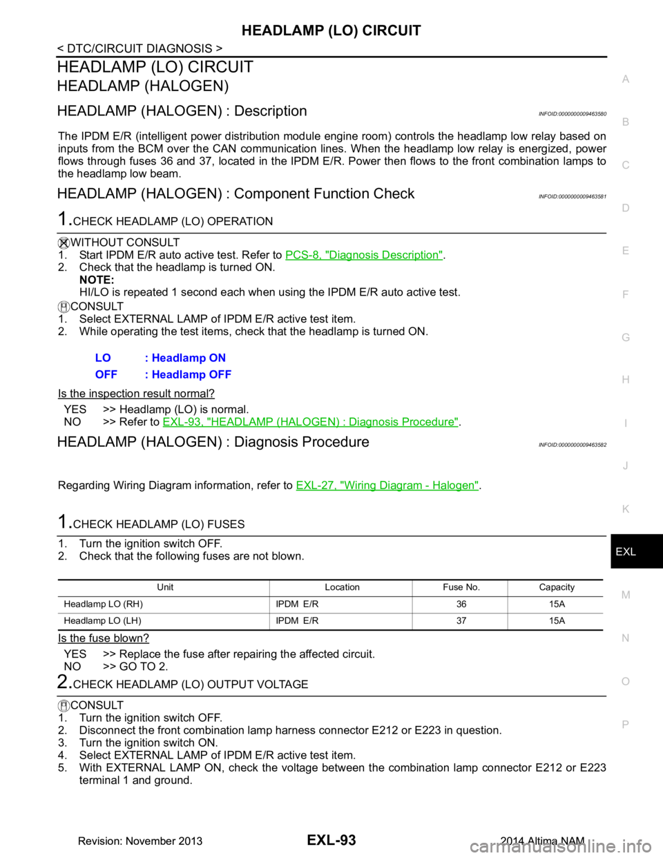
The IPDM E/R (intelligent power distribution modul e engine room) controls the headlamp low relay based on
inputs from the BCM over the CAN communication li nes. When the headlamp low relay is energized, power
flows through fuses 36 and 37, located in the IPDM E/R. Power then flows to the front combination lamps to
the headlamp low beam.
HEADLAMP (HALOGEN) : Component Function CheckINFOID:0000000009463581
1.CHECK HEADLAMP (LO) OPERATION
WITHOUT CONSULT
1. Start IPDM E/R auto active test. Refer to PCS-8, "Diagnosis Description"
.
2. Check that the headlamp is turned ON.
NOTE:
HI/LO is repeated 1 second each when using the IPDM E/R auto active test.
CONSULT
1. Select EXTERNAL LAMP of IP DM E/R active test item.
2. While operating the test items, check that the headlamp is turned ON.
Is the inspection result normal?
YES >> Headlamp (LO) is normal.
NO >> Refer to EXL-93, "HEADLAMP (HALOGEN) : Diagnosis Procedure"
.
HEADLAMP (HALOGEN) : Diagnosis ProcedureINFOID:0000000009463582
Regarding Wiring Diagram information, refer to EXL-27, "Wiring Diagram - Halogen".
1.CHECK HEADLAMP (LO) FUSES
1. Turn the ignition switch OFF.
2. Check that the following fuses are not blown.
Is the fuse blown?
YES >> Replace the fuse after repairing the affected circuit.
NO >> GO TO 2.
2.CHECK HEADLAMP (LO) OUTPUT VOLTAGE
CONSULT
1. Turn the ignition switch OFF.
2. Disconnect the front combination lamp harness connector E212 or E223 in question.
3. Turn the ignition switch ON.
4. Select EXTERNAL LAMP of IP DM E/R active test item.
5. With EXTERNAL LAMP ON, check the voltage betw een the combination lamp connector E212 or E223
terminal 1 and ground. LO : Headlamp ON
OFF : Headlamp OFF
Unit Location Fuse No. Capacity
Headlamp LO (RH) IPDM E/R 36 15A
Headlamp LO (L H) IPDM E/R 37 15A
Revision: November 20132014 Altima NAMRevision: November 20132014 Altima NAM
Page 2360 of 4801

EXL-94
< DTC/CIRCUIT DIAGNOSIS >
HEADLAMP (LO) CIRCUIT
Is the inspection result normal?
YES >> GO TO 4.
NO >> GO TO 3.
3.CHECK HEADLAMP (LO) CIRCUIT FOR OPEN
1. Turn the ignition switch OFF.
2. Disconnect IPDM E/R connector E200.
3. Check continuity between the IPDM E/R harness c onnector E200 and the front combination lamp harness
connector E223 or E212.
Is the inspection result normal?
YES >> Replace IPDM E/R. Refer to PCS-32, "Removal and Installation".
NO >> Repair or replace the harness or connector.
4.CHECK FRONT COMBINATION LAMP (LO) GROUND CIRCUIT
Check continuity between the front combination la mp harness connector E223 or E212 terminal 2 and ground.
Is the inspection result normal?
YES >> Inspect the headlamp bulb.
NO >> Repair or replace the harness or connector.
HEADLAMP (XENON)
HEADLAMP (XENON) : DescriptionINFOID:0000000009463583
The IPDM E/R (intelligent power distribution modul e engine room) controls the headlamp low relay based on
inputs from the BCM over the CAN communication li nes. When the headlamp low relay is energized, power
flows through fuses 36 and 37, located in the IPDM E/R. Power then flows to the front combination lamps to
the headlamp low beam.
HEADLAMP (XENON) : Component Function CheckINFOID:0000000009463584
1.CHECK HEADLAMP (LO) OPERATION
WITHOUT CONSULT
1. Start IPDM E/R auto active test. Refer to PCS-8, "Diagnosis Description"
.
2. Check that the headlamp is turned ON. NOTE:
HI/LO is repeated 1 second each when usi ng the IPDM E/R auto active test.
CONSULT
1. Select EXTERNAL LAMP of IP DM E/R active test item.
2. While operating the test items, c heck that the headlamp is turned ON.
(+)
(− )Voltage
Connector Terminal
RH E223 1 Ground Battery voltage
LH E212
IPDM E/R Front combination lamp Continuity
Connector Terminal Connector Terminal
RH E20075 E223
1Yes
LH 76 E212
Connector Terminal — Continuity
RH E223 2GroundYes
LH E212
Revision: November 20132014 Altima NAMRevision: November 20132014 Altima NAM
Page 2361 of 4801

HEADLAMP (LO) CIRCUITEXL-95
< DTC/CIRCUIT DIAGNOSIS >
C
D E
F
G H
I
J
K
M A
B
EXL
N
O P
Is the inspection result normal?
YES >> Headlamp (LO) is normal.
NO >> Refer to EXL-95, "HEADLAMP (XEN ON) : Diagnosis Procedure"
.
HEADLAMP (XENON) : Diagnosis ProcedureINFOID:0000000009463585
Regarding Wiring Diagram information, refer to EXL-33, "Wiring Diagram - Xenon".
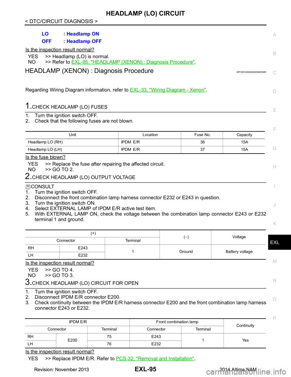
1.CHECK HEADLAMP (LO) FUSES
1. Turn the ignition switch OFF.
2. Check that the following fuses are not blown.
Is the fuse blown?
YES >> Replace the fuse after repairing the affected circuit.
NO >> GO TO 2.
2.CHECK HEADLAMP (LO) OUTPUT VOLTAGE
CONSULT
1. Turn the ignition switch OFF.
2. Disconnect the front combination lamp harness connector E232 or E243 in question.
3. Turn the ignition switch ON.
4. Select EXTERNAL LAMP of IP DM E/R active test item.
5. With EXTERNAL LAMP ON, check the voltage betw een the combination lamp connector E243 or E232
terminal 1 and ground.
Is the inspection result normal?
YES >> GO TO 4.
NO >> GO TO 3.
3.CHECK HEADLAMP (LO) CIRCUIT FOR OPEN
1. Turn the ignition switch OFF.
2. Disconnect IPDM E/R connector E200.
3. Check continuity between the IPDM E/R harness c onnector E200 and the front combination lamp harness
connector E243 or E232.
Is the inspection result normal?
YES >> Replace IPDM E/R. Refer to PCS-32, "Removal and Installation".
LO : Headlamp ON
OFF : Headlamp OFF
Unit Location Fuse No. Capacity
Headlamp LO (RH) IPDM E/R 36 15A
Headlamp LO (L H) IPDM E/R 37 15A
(+)
(− )Voltage
Connector Terminal
RH E243 1 Ground Battery voltage
LH E232
IPDM E/R Front combination lamp Continuity
Connector Terminal Connector Terminal
RH E20075 E243
1Yes
LH 76 E232
Revision: November 20132014 Altima NAMRevision: November 20132014 Altima NAM
Page 2363 of 4801

XENON HEADLAMPEXL-97
< DTC/CIRCUIT DIAGNOSIS >
C
D E
F
G H
I
J
K
M A
B
EXL
N
O P
XENON HEADLAMP
DescriptionINFOID:0000000009463586
OPERATION
Refer to EXL-9, "HEADLAMP SYSTEM : System Description".
PRECAUTIONS FOR TROUBLE DIAGNOSIS
• Installation or removal of the connecto r must be done with the lighting switch OFF.
• When the lamp is illuminated (when the lighting switch is ON), do not touch the harness, HID control unit,
inside of the lamp, or the lamp metal parts.
• To check illumination, temporarily install lamp in the vehicle. Be sure to connect power at the vehicle-side
connector.
• If the malfunction can be traced directly to the electrical system, first check for items such as blown fuses
and fusible links, broken wires or loose connectors , pulled-out terminals, and improper connections.
• Do not work with wet hands.
• Using a tester for HID control unit circuit trouble diagnosis is prohibited.
• Disassembling the HID control unit or harnesses (bul b socket harness, ballast harness) is prohibited.
• Immediately after illumination, the light int ensity and color will fluctuate, this is normal.
• When the bulb has reached the end of its lifetime, the br ightness may drop significantly, it may flash repeat-
edly, or the light may turn a reddish color.
Diagnosis ProcedureINFOID:0000000009463587
1.CHECK XENON BULB
Install a known good bulb to the applicable headlamp. Check that the headlamp operates.
Is the inspection result normal?
YES >> Replace the xenon bulb.
NO >> GO TO 2.
2.CHECK HID CONTROL UNIT
Install a known good HID control unit to the appl icable headlamp. Check that the headlamp operates.
Is the inspection result normal?
YES >> Replace HID control unit.
NO >> Inspection End.
Revision: November 20132014 Altima NAMRevision: November 20132014 Altima NAM
Page 2369 of 4801

PARKING LAMP CIRCUITEXL-103
< DTC/CIRCUIT DIAGNOSIS >
C
D E
F
G H
I
J
K
M A
B
EXL
N
O P
PARKING LAMP CIRCUIT
DescriptionINFOID:0000000009463594
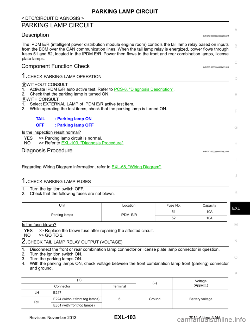
The IPDM E/R (intelligent power distribution module engi ne room) controls the tail lamp relay based on inputs
from the BCM over the CAN communication lines. When t he tail lamp relay is energized, power flows through
fuses 51 and 52, located in the IPDM E/R. Power then fl ows to the front and rear combination lamps, license
plate lamps.
Component Function CheckINFOID:0000000009463595
1.CHECK PARKING LAMP OPERATION
WITHOUT CONSULT
1. Activate IPDM E/R auto active test. Refer to PCS-8, "Diagnosis Description"
.
2. Check that the parking lamp is turned ON.
WITH CONSULT
1. Select EXTERNAL LAMP of IP DM E/R active test item.
2. While operating the test items, check that the parking lamp is turned ON.
Is the inspection result normal?
YES >> Parking lamp circuit is normal.
NO >> Refer to EXL-103, "Diagnosis Procedure"
.
Diagnosis ProcedureINFOID:0000000009463596
Regarding Wiring Diagram information, refer to EXL-68, "Wiring Diagram".
1.CHECK PARKING LAMP FUSES
1. Turn the ignition switch OFF.
2. Check that the following fuses are not blown.
Is the fuse blown?
YES >> Replace the blown fuse after repairing the affected circuit.
NO >> GO TO 2.
2.CHECK TAIL LAMP RELAY OUTPUT (VOLTAGE)
1. Disconnect the front or rear combination lamp connector or license plate lamp connector in question.
2. Turn the ignition switch ON.
3. Turn the parking lamps ON.
4. With the parking lamps ON, check voltage between t he front combination lamp front (parking) connector
and ground. TAIL : Parking lamp ON
OFF : Parking lamp OFF
Unit Location Fuse No. Capacity
Parking lamps IPDM E/R 51 10A
52 10A
(+) (− ) Vo l ta g e
(Approx.)
Connector Terminal
LH E217 6 Ground Battery voltage
RH E224 (without front fog lamps)
E351 (with front fog lamps)
Revision: November 20132014 Altima NAMRevision: November 20132014 Altima NAM