2014 NISSAN TEANA fog light bulb
[x] Cancel search: fog light bulbPage 2365 of 4801

DAYTIME LIGHT RELAY CIRCUITEXL-99
< DTC/CIRCUIT DIAGNOSIS >
C
D E
F
G H
I
J
K
M A
B
EXL
N
O P
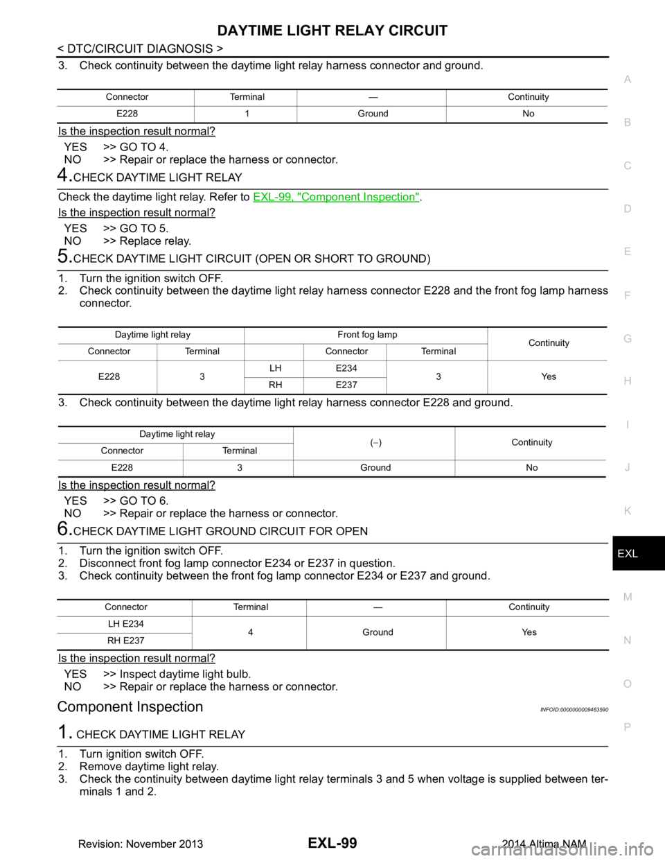
3. Check continuity between the daytime light relay harness connector and ground.
Is the inspection result normal?
YES >> GO TO 4.
NO >> Repair or replace the harness or connector.
4.CHECK DAYTIME LIGHT RELAY
Check the daytime light relay. Refer to EXL-99, "Component Inspection"
.
Is the inspection result normal?
YES >> GO TO 5.
NO >> Replace relay.
5.CHECK DAYTIME LIGHT CIRCUIT (OPEN OR SHORT TO GROUND)
1. Turn the ignition switch OFF.
2. Check continuity between the daytime light rela y harness connector E228 and the front fog lamp harness
connector.
3. Check continuity between the daytime light relay harness connector E228 and ground.
Is the inspection result normal?
YES >> GO TO 6.
NO >> Repair or replace the harness or connector.
6.CHECK DAYTIME LIGHT GROUND CIRCUIT FOR OPEN
1. Turn the ignition switch OFF.
2. Disconnect front fog lamp connector E234 or E237 in question.
3. Check continuity between the front fog lamp connector E234 or E237 and ground.
Is the inspection result normal?
YES >> Inspect daytime light bulb.
NO >> Repair or replace the harness or connector.
Component InspectionINFOID:0000000009463590
1. CHECK DAYTIME LIGHT RELAY
1. Turn ignition switch OFF.
2. Remove daytime light relay.
3. Check the continuity between daytime light relay terminals 3 and 5 when voltage is supplied between ter- minals 1 and 2.
Connector Terminal — Continuity
E228 1 Ground No
Daytime light relay Front fog lamp Continuity
Connector Terminal Connector Terminal
E228 3 LH E234
3Yes
RH E237
Daytime light relay (− )Continuity
Connector Terminal
E228 3 Ground No
Connector Terminal — ContinuityLH E234 4Ground Yes
RH E237
Revision: November 20132014 Altima NAMRevision: November 20132014 Altima NAM
Page 2381 of 4801

EXTERIOR LIGHTING SYSTEM SYMPTOMSEXL-115
< SYMPTOM DIAGNOSIS >
C
D E
F
G H
I
J
K
M A
B
EXL
N
O P
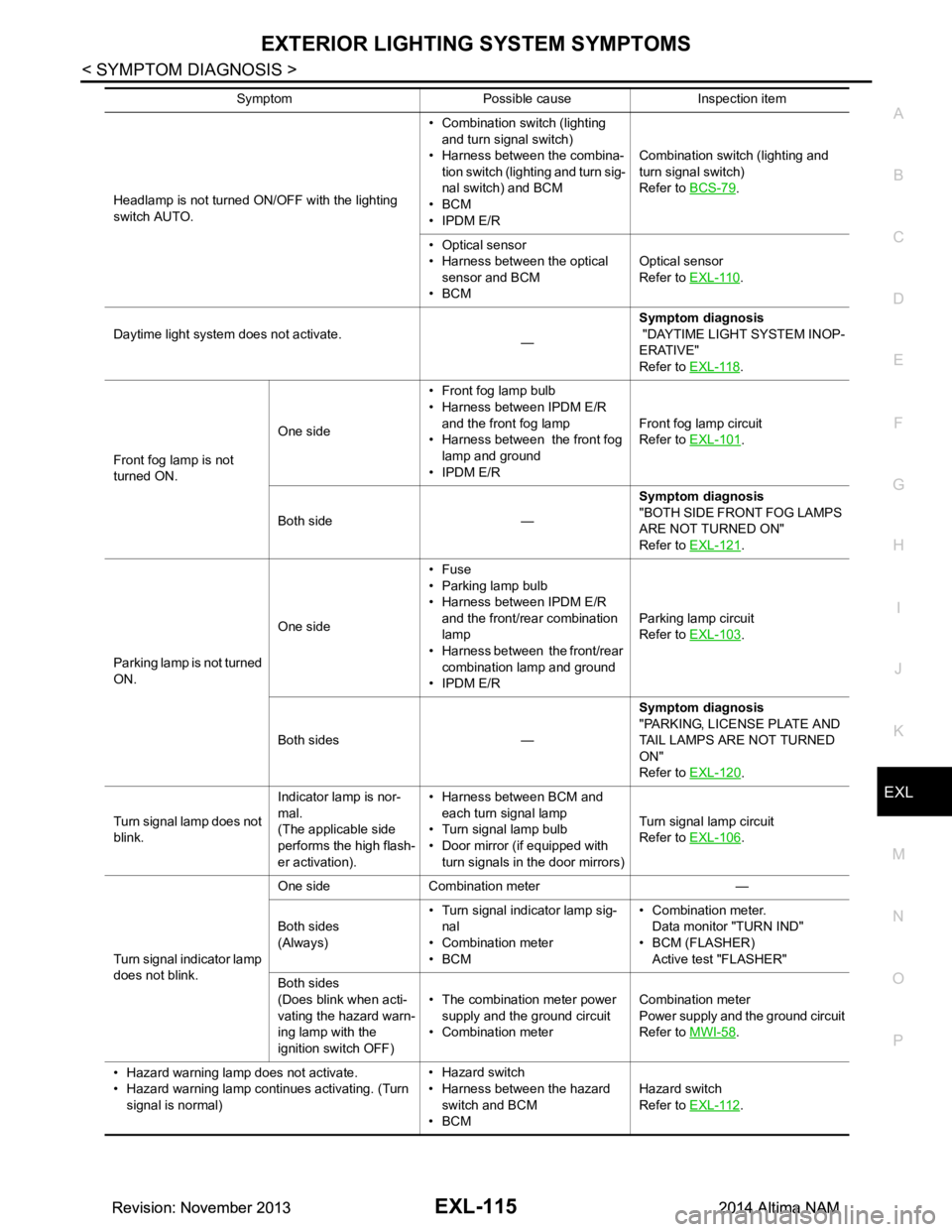
Headlamp is not turned ON/OFF with the lighting
switch AUTO. • Combination switch (lighting
and turn signal switch)
• Harness between the combina- tion switch (lighting and turn sig-
nal switch) and BCM
•BCM
• IPDM E/R Combination switch (lighting and
turn signal switch)
Refer to BCS-79.
• Optical sensor
• Harness between the optical
sensor and BCM
•BCM Optical sensor
Refer to EXL-110
.
Daytime light system does not activate. —Symptom diagnosis
"DAYTIME LIGHT SYSTEM INOP-
ERATIVE"
Refer to EXL-118
.
Front fog lamp is not
turned ON. One side
• Front fog lamp bulb
• Harness between IPDM E/R
and the front fog lamp
• Harness between the front fog lamp and ground
• IPDM E/R Front fog lamp circuit
Refer to EXL-101
.
Both side — Symptom diagnosis
"BOTH SIDE FRONT FOG LAMPS
ARE NOT TURNED ON"
Refer to EXL-121
.
Parking lamp is not turned
ON. One side•Fuse
• Parking lamp bulb
• Harness between IPDM E/R
and the front/rear combination
lamp
• Harness between the front/rear
combination lamp and ground
• IPDM E/R Parking lamp circuit
Refer to EXL-103
.
Both sides — Symptom diagnosis
"PARKING, LICENSE PLATE AND
TAIL LAMPS ARE NOT TURNED
ON"
Refer to EXL-120
.
Turn signal lamp does not
blink. Indicator lamp is nor-
mal.
(The applicable side
performs the high flash-
er activation). • Harness between BCM and
each turn signal lamp
• Turn signal lamp bulb
• Door mirror (if equipped with
turn signals in the door mirrors) Turn signal lamp circuit
Refer to EXL-106
.
Turn signal indicator lamp
does not blink. One side Combination meter —
Both sides
(Always) • Turn signal indicator lamp sig-
nal
• Combination meter
•BCM • Combination meter.
Data monitor "TURN IND"
• BCM (FLASHER) Active test "FLASHER"
Both sides
(Does blink when acti-
vating the hazard warn-
ing lamp with the
ignition switch OFF) • The combination meter power
supply and the ground circuit
• Combination meter Combination meter
Power supply and the ground circuit
Refer to MWI-58
.
• Hazard warning lamp does not activate.
• Hazard warning lamp continues activating. (Turn signal is normal) • Hazard switch
• Harness between the hazard switch and BCM
•BCM Hazard switch
Refer to EXL-112
.
Symptom Possible cause Inspection item
Revision: November 20132014 Altima NAMRevision: November 20132014 Altima NAM
Page 2390 of 4801

EXL-124
< PERIODIC MAINTENANCE >
FRONT FOG LAMP
FRONT FOG LAMP
Aiming AdjustmentINFOID:0000000009463618
PREPARATION BEFORE ADJUSTING
The fog lamp is a semi-sealed beam type which uses a replaceable halogen bulb. Before performing aiming
adjustment procedure, check the following:
• Ensure all tires are inflated to correct pressure.
• Place vehicle and screen on level surface.
• Ensure there is no load in vehicle other than the driver (or equivalent weight placed in driver's position).
• Coolant and engine oil filled to correct level, and fuel tank full.
• Remove cargo and/or luggage to maintain an unloaded vehicle condition.
• Confirm spare tire, jack and tools are properly stowed.
• Carefully wipe off any dirt from headlamp lens. CAUTION:
Do not use organic solvent (thinner, gasoline etc.)
• Place a driver or equivalent weight of 68.5 kg (150 lb) on the driver seat.
• By hand, bounce the front and rear of the vehicle to settle the suspension and eliminate any static load.
• Place the front tires in the straight ahead position.
• Aim each headlamp individually and ensure other headlamp beam pattern is blocked from screen.
NOTE:
• For headlamp aiming details, refer to regulations in your area.
• By regulation, no means for horizontal aim adjustment is provided from the factory; only vertical aim is
adjustable.
• Use adjusting screw to perform aiming adjustment.
• Perform headlamp aiming if:
- The vehicle front body has been repaired.
- The front combination lamp has been removed or replaced.
- Any outfitting has been installed.
- The vehicle’s standard load condition has been substantially increased.
Aiming Adjustment Procedure
1. Place the screen. NOTE:
• Stop the vehicle facing the wall.
• Place the board on a plain road vertically.
2. Face the vehicle with the screen. Maintain 7.62 m (25.0 ft) between the front fog lamp center and the
screen.
3. Start the engine. Turn the front fog lamp ON. NOTE:
Shut off the headlamp light with the board to prevent from illuminating the adjustment screen.
CAUTION:
Do not cover the lens surface with a tape etc. The lens is made of resin.
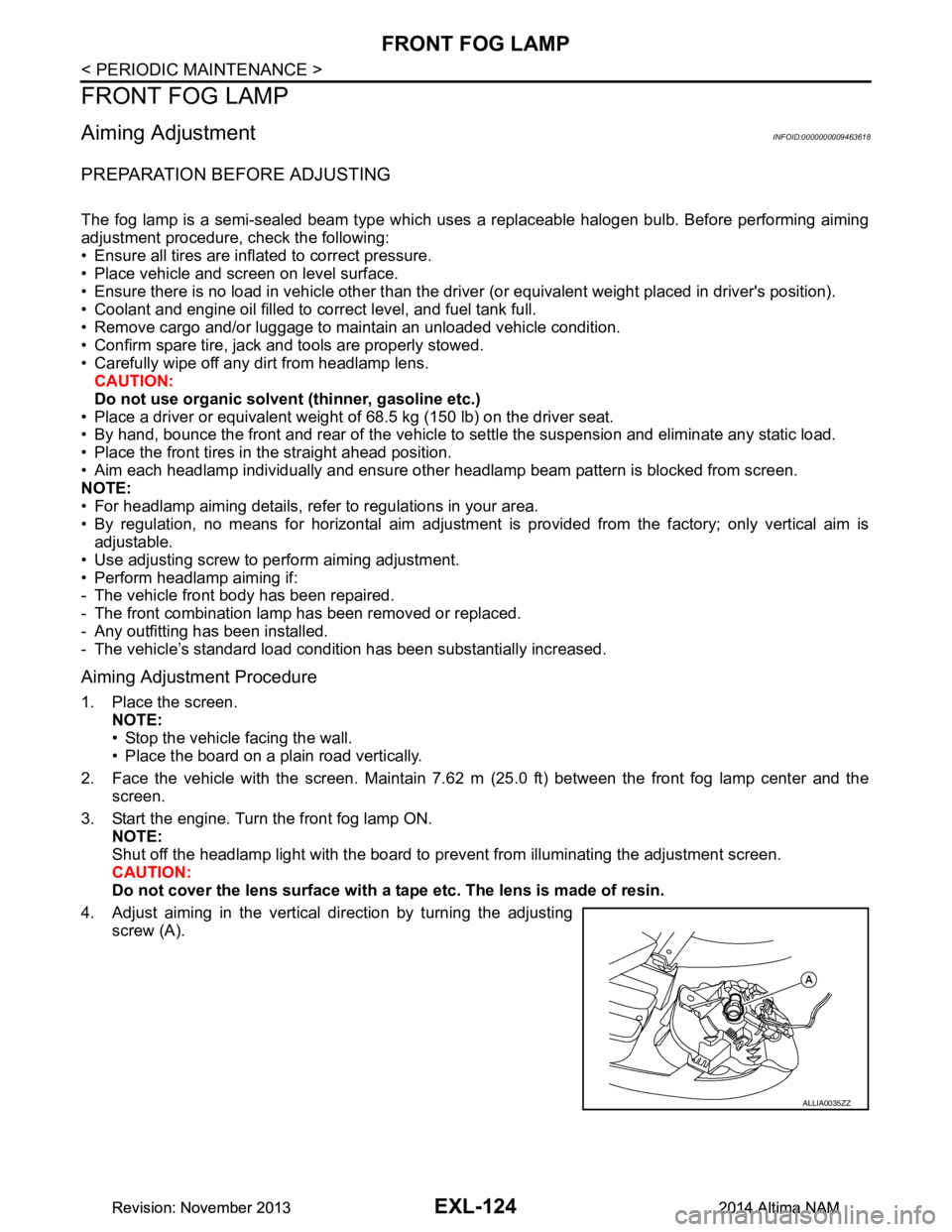
4. Adjust aiming in the vertical direction by turning the adjusting screw (A).
ALLIA0035ZZ
Revision: November 20132014 Altima NAMRevision: November 20132014 Altima NAM
Page 2397 of 4801

FRONT FOG LAMPEXL-131
< REMOVAL AND INSTALLATION >
C
D E
F
G H
I
J
K
M A
B
EXL
N
O P
FRONT FOG LAMP
Removal and InstallationINFOID:0000000009463627
REMOVAL
1. Remove the front fender protector side cover.
2. Position the fender protector aside. Refer to EXT-26, "FENDER PROTECTOR : Removal and Installa-
tion".
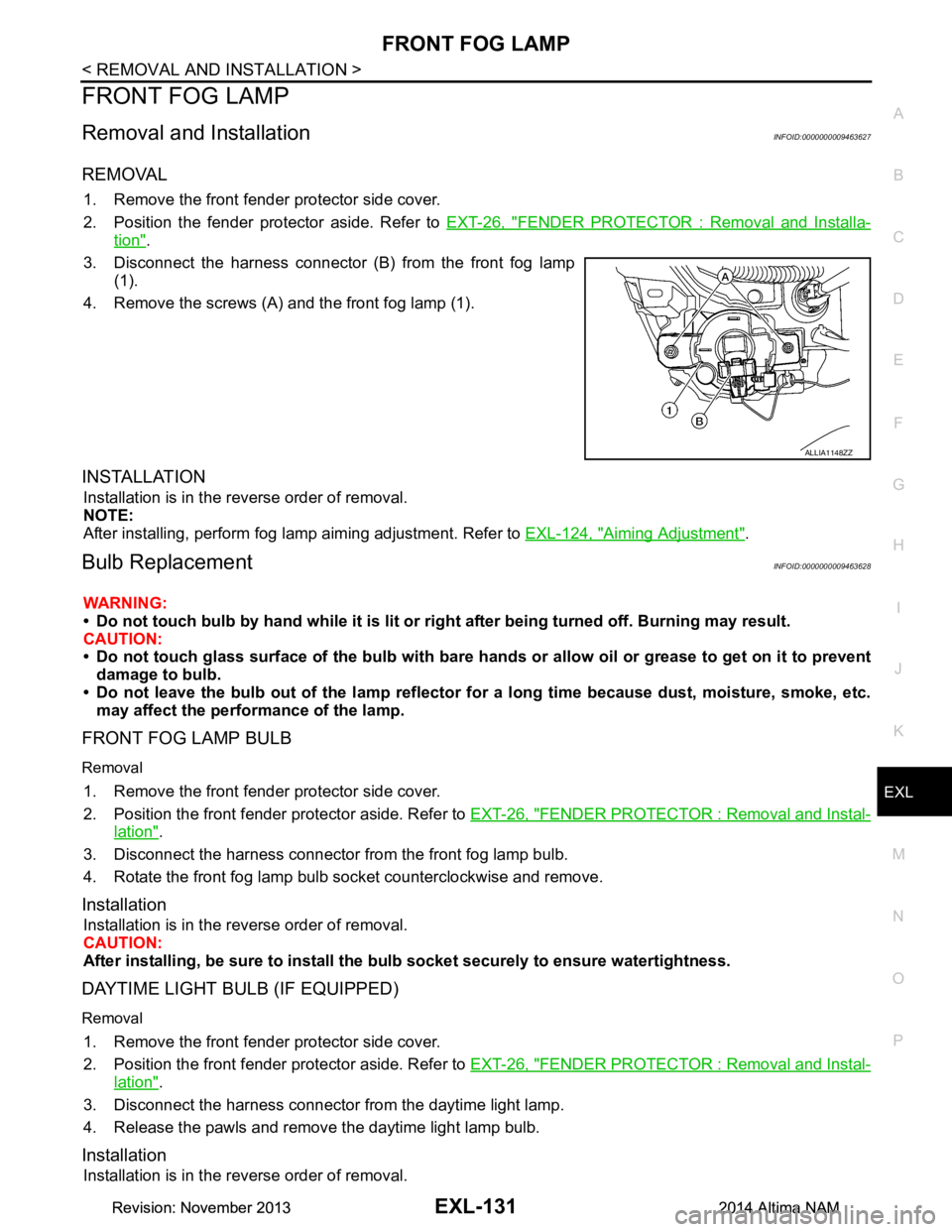
3. Disconnect the harness connector (B) from the front fog lamp (1).
4. Remove the screws (A) and the front fog lamp (1).
INSTALLATION
Installation is in the reverse order of removal.
NOTE:
After installing, perform fog lamp aiming adjustment. Refer to EXL-124, "Aiming Adjustment"
.
Bulb ReplacementINFOID:0000000009463628
WARNING:
• Do not touch bulb by hand while it is lit or right after being turned off. Burning may result.
CAUTION:
• Do not touch glass surface of the bulb with bare hand s or allow oil or grease to get on it to prevent
damage to bulb.
• Do not leave the bulb out of the lamp reflector fo r a long time because dust, moisture, smoke, etc.
may affect the performance of the lamp.
FRONT FOG LAMP BULB
Removal
1. Remove the front fender protector side cover.
2. Position the front fender pr otector aside. Refer to EXT-26, "FENDER PROTECTOR : Removal and Instal-
lation".
3. Disconnect the harness connector from the front fog lamp bulb.
4. Rotate the front fog lamp bulb socket counterclockwise and remove.
Installation
Installation is in the reverse order of removal.
CAUTION:
After installing, be sure to install the bulb socket securely to ensure watertightness.
DAYTIME LIGHT BULB (IF EQUIPPED)
Removal
1. Remove the front fender protector side cover.
2. Position the front fender pr otector aside. Refer to EXT-26, "FENDER PROTECTOR : Removal and Instal-
lation".
3. Disconnect the harness connector from the daytime light lamp.
4. Release the pawls and remove the daytime light lamp bulb.
Installation
Installation is in the reverse order of removal.
ALLIA1148ZZ
Revision: November 20132014 Altima NAMRevision: November 20132014 Altima NAM