2014 NISSAN TEANA warning lights
[x] Cancel search: warning lightsPage 916 of 4801

DLK-148
< DTC/CIRCUIT DIAGNOSIS >
WARNING CHIME FUNCTION
WARNING CHIME FUNCTION
DescriptionINFOID:0000000009461898
Performs operation method guide and warning with buzzer.
Component Function CheckINFOID:0000000009461899
1.CHECK FUNCTION
With CONSULT
1. Check the operation with “INSIDE BUZZER” in the Active Test.
2. Touch “TAKE OUT”, “KNOB”or “KEY”on screen.
Is the inspection result normal?
YES >> Warning buzzer into combination meter is OK.
NO >> Refer to DLK-148, "Diagnosis Procedure"
.
Diagnosis ProcedureINFOID:0000000009461900
1.CHECK METER BUZZER CIRCUIT
Operate the hazard lights by turni ng ON the hazard warning switch.
Is the inspection result normal?
YES >> GO TO 2
NO >> Replace combination meter. Refer to MWI-82, "Removal and Installation"
.
2.CHECK INTERMITTENT INCIDENT
Refer to GI-43, "Intermittent Incident"
.
>> Inspection End.
Revision: November 20132014 Altima NAMRevision: November 20132014 Altima NAM
Page 917 of 4801

HAZARD FUNCTIONDLK-149
< DTC/CIRCUIT DIAGNOSIS >
C
D E
F
G H
I
J
L
M A
B
DLK
N
O P
HAZARD FUNCTION
DescriptionINFOID:0000000009461901
Perform answer-back for each oper ation with number of blinks.
Component Function CheckINFOID:0000000009461902
1.CHECK FUNCTION
Check hazard warning lamp (“FLASHER”) in Active Test.
Is the inspection result normal?
YES >> Hazard warning lamp circuit is OK.
NO >> Refer to EXL-60, "Wiring Diagram"
.
Diagnosis ProcedureINFOID:0000000009461903
1.CHECK HAZARD SWITCH CIRCUIT
Operate the hazard lights by turni ng ON the hazard warning switch.
Is the inspection result normal?
YES >> GO TO 2
NO >> Repair or replace hazard warning switch circuit. Refer to EXL-86, "Work Flow"
.
2.CHECK INTERMITTENT INCIDENT
Refer to GI-43, "Intermittent Incident"
.
>> Inspection End.
Revision: November 20132014 Altima NAMRevision: November 20132014 Altima NAM
Page 2277 of 4801

SYSTEMEXL-11
< SYSTEM DESCRIPTION >
C
D E
F
G H
I
J
K
M A
B
EXL
N
O P
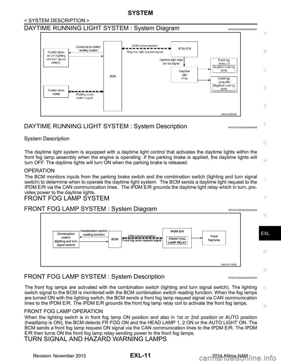
DAYTIME RUNNING LIGHT SY STEM : System DiagramINFOID:0000000009463547
DAYTIME RUNNING LIGHT SYST EM : System DescriptionINFOID:0000000009463548
System Description
The daytime light system is equipped with a daytime light control that activates the daytime lights within the
front fog lamp assembly when the engine is operating. If the parking brake is applied, the daytime lights will
turn OFF. The daytime lights will turn ON when the parking brake is released.
OPERATION
The BCM monitors inputs from the parking brake swit ch and the combination switch (lighting and turn signal
switch) to determine when to operate the daytime light s ystem. The BCM sends a daytime light request to the
IPDM E/R via the CAN communication lines. The IPDM E/ R grounds the daytime light relay which in turn, pro-
vides power to the daytime lights.
FRONT FOG LAMP SYSTEM
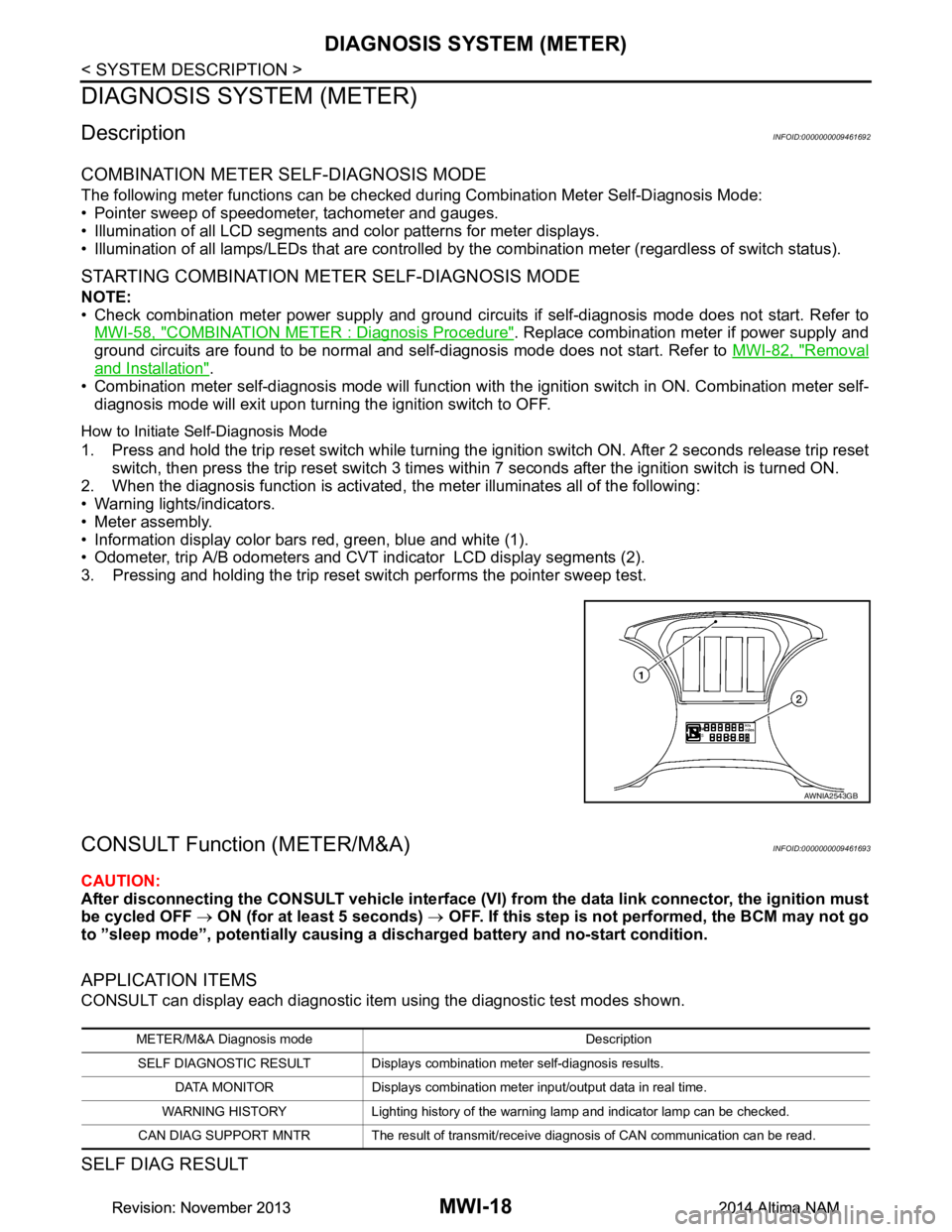
FRONT FOG LAMP SYSTEM : System DiagramINFOID:0000000009463549
FRONT FOG LAMP SYSTEM : System DescriptionINFOID:0000000009463550
The front fog lamps are activated with the combination switch (lighting and turn signal switch). The lighting
switch signal to the BCM is monitored with the BCM combination switch reading function. When the fog lamps
are turned ON with the lighting switch, the BCM sends a front fog lamp request signal via CAN communication
lines to the IPDM E/R. The IPDM E/R grounds the front fog lamp relay coil to activate the front fog lamps.
FRONT FOG LAMP OPERATION
When the lighting switch is in front fog lamp ON position and also in 1st or 2nd position or AUTO position
(headlamp is ON), the BCM detects FR FOG ON and the HEAD LAMP 1, 2 ON or the AUTO LIGHT ON. The
BCM sends a front fog lamp request ON signal via the CAN communication lines to the IPDM E/R. The IPDM
E/R then turns ON the front fog lamp re lay sending power to the front fog lamps.
TURN SIGNAL AND HAZARD WARNING LAMPS
AWLIA1965GB
AWLIA1719GB
Revision: November 20132014 Altima NAMRevision: November 20132014 Altima NAM
Page 3273 of 4801

MWI-18
< SYSTEM DESCRIPTION >
DIAGNOSIS SYSTEM (METER)
DIAGNOSIS SYSTEM (METER)
DescriptionINFOID:0000000009461692
COMBINATION METER SELF-DIAGNOSIS MODE
The following meter functions can be checked during Combination Meter Self-Diagnosis Mode:
• Pointer sweep of speedometer, tachometer and gauges.
• Illumination of all LCD segments and color patterns for meter displays.
• Illumination of all lamps/LEDs that are controlled by the combination meter (regardless of switch status).
STARTING COMBINATION METER SELF-DIAGNOSIS MODE
NOTE:
• Check combination meter power supply and ground circuits if self-diagnosis mode does not start. Refer to
MWI-58, "COMBINATION METER : Diagnosis Procedure"
. Replace combination meter if power supply and
ground circuits are found to be normal and self-diagnosis mode does not start. Refer to MWI-82, "Removal
and Installation".
• Combination meter self-diagnosis mode will function with t he ignition switch in ON. Combination meter self-
diagnosis mode will exit upon turning the ignition switch to OFF.
How to Initiate Self-Diagnosis Mode
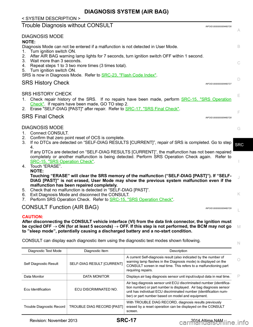
1. Press and hold the trip reset switch while turning the ignition switch ON. After 2 seconds release trip reset switch, then press the trip reset switch 3 times within 7 seconds after the ignition switch is turned ON.
2. When the diagnosis function is activated, the meter illuminates all of the following:
• Warning lights/indicators.
• Meter assembly.
• Information display color bars red, green, blue and white (1).
• Odometer, trip A/B odometers and CVT indicator LCD display segments (2).
3. Pressing and holding the trip reset switch performs the pointer sweep test.
CONSULT Function (METER/M&A)INFOID:0000000009461693
CAUTION:
After disconnecting the CONSULT vehicle interface (VI) from the data link connector, the ignition must
be cycled OFF → ON (for at least 5 seconds) → OFF. If this step is not performed, the BCM may not go
to ”sleep mode”, potentially causing a di scharged battery and no-start condition.
APPLICATION ITEMS
CONSULT can display each diagnostic item using the diagnostic test modes shown.
SELF DIAG RESULT
AWNIA2543GB
METER/M&A Diagnosis mode Description
SELF DIAGNOSTIC RESULT Displays combin ation meter self-diagnosis results.
DATA MONITOR Displays combination meter input/output data in real time.
WARNING HISTORY Lighting history of the warning lamp and indicator lamp can be checked.
CAN DIAG SUPPORT MNTR The result of transmit/receive diagnosis of CAN communication can be read.
Revision: November 20132014 Altima NAMRevision: November 20132014 Altima NAM
Page 4010 of 4801

DIAGNOSIS SYSTEM (AIR BAG)SRC-17
< SYSTEM DESCRIPTION >
C
D E
F
G
I
J
K L
M A
B
SRC
N
O P
Trouble Diagnosis without CONSULTINFOID:0000000009460726
DIAGNOSIS MODE
NOTE:
Diagnosis Mode can not be entered if a malfunction is not detected in User Mode.
1. Turn ignition switch ON.
2. After AIR BAG warning lamp lights for 7 seconds, turn ignition switch OFF within 1 second.
3. Wait more than 3 seconds.
4. Repeat steps 1 to 3 two more times (3 times total).
5. Turn ignition switch ON.
SRS is now in Diagnosis Mode. Refer to SRC-23, "Flash Code Index"
.
SRS History CheckINFOID:0000000009460727
SRS HISTORY CHECK
1. Check repair history of the SRS. If no repairs have been made, perform SRC-15, "SRS Operation
Check". If repairs have been made, GO TO step 2.
2. Erase "SELF-DIAG [PAST]" after repair. Refer to SRC-17, "SRS Final Check"
.
SRS Final CheckINFOID:0000000009460728
DIAGNOSIS MODE
1. Connect CONSULT.
2. Confirm that zero point reset of OCS is complete.
3. If no DTCs are detected on “SELF- DIAG RESULTS [CURRENT]”, repair of SRS is completed. Go to step
4.
If any DTCs are detected on “SEL F-DIAG RESULTS [CURRENT]”, t he malfunction has not been repaired
completely or another malfunction is being detected. Perform SRS Operation Check again. Refer to
SRC-15, "SRS Operation Check"
.
4. Touch “ERASE”. NOTE:
Touching “ERASE” will clear the SRS memory of the malfunction (“SELF-DIAG [PAST]”). If “SELF-
DIAG [PAST]” is not erased, User Mode may s how the previous system malfunction even if the
malfunction has been repaired completely.
5. Check that no malfunction is detected in “SELF-DIAG [PAST]”.
6. Exit Diagnosis Mode and disconnect the CONSULT.
7. Perform SRS Operation Check. Refer to SRC-15, "SRS Operation Check"
.
CONSULT Function (AIR BAG)INFOID:0000000009460729
CAUTION:
After disconnecting the CONSULT vehicle interface (VI) from the data link connector, the ignition must
be cycled OFF → ON (for at least 5 seconds) → OFF. If this step is not performed, the BCM may not go
to ”sleep mode”, potentiall y causing a discharged battery and a no-start condition.
CONSULT can display each diagnostic item using the diagnostic test modes shown following.
Diagnostic Test Mode Diagnostic Item Description
Self Diagnostic Result SEL F-DIAG RESULT [CURRENT]A current Self-diagnosis result (also indicated by the number of
warning lamp flashes in the Diagnosis mode) is displayed on the
CONSULT screen in real time. This refers to a malfunctioning part
requiring repairs.
Data Monitor DATA MONITOR Displays air bag diagnosis sensor unit input/output data in real time.
Ecu Identification ECU DISCRIMINATED NO. Air bag diagnosis sensor unit ECU discriminated number (identifica-
tion number) or part number is displayed. Air bag diagnosis sensor
unit has individual ECU discriminated number (identification num-
ber) or part number based on model and equipment.
Trouble Diagnostic Record TROUBLE DIAG RECORD [PAST] With TROUBLE DIAG RECORD, diagnosis results previously
erased by a reset operation can be displayed on the CONSULT
screen.
Revision: November 20132014 Altima NAMRevision: November 20132014 Altima NAM
Page 4256 of 4801
![NISSAN TEANA 2014 Service Manual
DIAGNOSIS SYSTEM (TCM)TM-41
< SYSTEM DESCRIPTION > [CVT: RE0F10D]
C
EF
G H
I
J
K L
M A
B
TM
N
O P
DIAGNOSIS SYSTEM (TCM)
DIAGNOSIS DESCRIPTION
DIAGNOSIS DESCRIPTION : 1 Tr ip Detection Diagnosis and NISSAN TEANA 2014 Service Manual
DIAGNOSIS SYSTEM (TCM)TM-41
< SYSTEM DESCRIPTION > [CVT: RE0F10D]
C
EF
G H
I
J
K L
M A
B
TM
N
O P
DIAGNOSIS SYSTEM (TCM)
DIAGNOSIS DESCRIPTION
DIAGNOSIS DESCRIPTION : 1 Tr ip Detection Diagnosis and](/manual-img/5/57390/w960_57390-4255.png)
DIAGNOSIS SYSTEM (TCM)TM-41
< SYSTEM DESCRIPTION > [CVT: RE0F10D]
C
EF
G H
I
J
K L
M A
B
TM
N
O P
DIAGNOSIS SYSTEM (TCM)
DIAGNOSIS DESCRIPTION
DIAGNOSIS DESCRIPTION : 1 Tr ip Detection Diagnosis and 2 Trip Detection Diagno-
sis
INFOID:0000000009463996
NOTE:
“Start the engine and turn OFF the ignition switch after warm-up.” This is defined as 1 trip.
1 TRIP DETECTION DIAGNOSIS
When initial malfunction is detected, TCM memorize s DTC. In these diagnoses, some illuminate MIL and
some do not. Refer to TM-60, "DTC Index"
.
2 TRIP DETECTION DIAGNOSIS
When initial malfunction is detected, TCM memorizes DTC of the 1st trip. MIL does not light at this stage. <1
trip>
If the same malfunction is detected again in next drivi ng, TCM memorizes DTC. When DTC is memorized, MIL
lights. <2 trip>
“Trip” of the “2 trip detection diagnosis” indicates the driving mode that executes self-diagnosis during driving.
×: Check possible —: Check not possible
DIAGNOSIS DESCRIPTION : DTC and DTC of 1st TripINFOID:0000000009463997
2 TRIP DETECTION DIAGNOSIS THAT ILLUMINATES MIL
• The DTC number of the 1st trip is the same as the DTC number.
• When a malfunction is detected at the 1st trip, TCM memo rizes DTC of the 1st trip. MIL does not light at this
stage. If the same malfunction is not detected at t he 2nd trip (conforming to necessary driving conditions),
DTC at the 1st trip is erased from TCM. If the same malfunction is detected at the 2nd trip, TCM memorizes
DTC and MIL lights at the same time.
• The DTC of the 1st trip is specified in Service $01 of SAE J1979/ISO 15031-5. Since detection of DTC at the
1st trip does not illuminate MIL, warning for a problem is not given to a driver.
• For procedure to delete DTC and 1st trip DTC from TCM, refer to TM-43, "CONSULT Function"
.
• If DTC of the 1st trip is detected, it is necessary to check the cause according to the “Diagnosis flow”. Refer
to TM-77, "Flowchart of Trouble Diagnosis"
.
DIAGNOSIS DESCRIPTION : Malf unction Indicator Lamp (MIL)INFOID:0000000009463998
• TCM not only detects DTC, but also sends the MI L signal to ECM through CAN communication. ECM sends
the MIL signal to the combination meter through CAN communication according to the signal, and illumi-
nates MIL.
• For malfunction indicator lamp (MIL) description, refer to EC-74, "DIAGNOSIS DESCRIPTION : Malfunction
Indicator Lamp (MIL)".
DIAGNOSIS DESCRIPTION : Counter SystemINFOID:0000000009463999
RELATION BETWEEN DTC AT 1ST TRIP/DTC/MIL AND DRIVING CONDITIONS (FOR 2 TRIP DE-
TECTION DIAGNOSIS THAT ILLUMINATES MIL)
• When initial malfunction is detected, TCM memorizes DT C of the 1st trip. MIL does not light at this stage.
• If the same malfunction is detect ed at the 2nd trip, TCM memorizes DTC and MIL lights at the same time.
• Then, MIL goes after driving the vehicle for 3 tr ips under “Driving condition B” without malfunction.
• DTC is displayed until 40 trips of “Driving condition A” are satisfied without detecting the same malfunction.
DTC is erased when 40 trips are satisfied.
Item DTC at the 1st trip DTC MIL
Display at the 1st trip Display at the
2nd trip Display at the
1st trip Display at the
2nd trip Illumination at
the 1st trip Illumination at
the 2nd trip
1 trip detection diagnosis
(Refer to TM-60, "DTC Index"
) ——
×— ×—
2 trip detection diagnosis
(Refer to TM-60, "DTC Index"
) ×
—— ×— ×
Revision: November 20132014 Altima NAMRevision: November 20132014 Altima NAM
Page 4458 of 4801
![NISSAN TEANA 2014 Service Manual
DIAGNOSIS SYSTEM (TCM)TM-243
< SYSTEM DESCRIPTION > [CVT: RE0F10E]
C
EF
G H
I
J
K L
M A
B
TM
N
O P
DIAGNOSIS SYSTEM (TCM)
DIAGNOSIS DESCRIPTION
DIAGNOSIS DESCRIPTION : 1 Tr ip Detection Diagnosis an NISSAN TEANA 2014 Service Manual
DIAGNOSIS SYSTEM (TCM)TM-243
< SYSTEM DESCRIPTION > [CVT: RE0F10E]
C
EF
G H
I
J
K L
M A
B
TM
N
O P
DIAGNOSIS SYSTEM (TCM)
DIAGNOSIS DESCRIPTION
DIAGNOSIS DESCRIPTION : 1 Tr ip Detection Diagnosis an](/manual-img/5/57390/w960_57390-4457.png)
DIAGNOSIS SYSTEM (TCM)TM-243
< SYSTEM DESCRIPTION > [CVT: RE0F10E]
C
EF
G H
I
J
K L
M A
B
TM
N
O P
DIAGNOSIS SYSTEM (TCM)
DIAGNOSIS DESCRIPTION
DIAGNOSIS DESCRIPTION : 1 Tr ip Detection Diagnosis and 2 Trip Detection Diagno-
sis
INFOID:0000000009464213
NOTE:
“Start the engine and turn OFF the ignition switch after warm-up.” This is defined as 1 trip.
1 TRIP DETECTION DIAGNOSIS
When initial malfunction is detected, TCM memorize s DTC. In these diagnoses, some illuminate MIL and
some do not. Refer to TM-263, "DTC Index"
.
2 TRIP DETECTION DIAGNOSIS
When initial malfunction is detected, TCM memorizes DTC of the 1st trip. MIL does not light at this stage. <1
trip>
If the same malfunction is detected again in next drivi ng, TCM memorizes DTC. When DTC is memorized, MIL
lights. <2 trip>
“Trip” of the “2 trip detection diagnosis” indicates the driving mode that executes self-diagnosis during driving.
×: Check possible —: Check not possible
DIAGNOSIS DESCRIPTION : DTC and DTC of 1st TripINFOID:0000000009464214
2 TRIP DETECTION DIAGNOSIS THAT ILLUMINATES MIL
• The DTC number of the 1st trip is the same as the DTC number.
• When a malfunction is detected at the 1st trip, TCM memo rizes DTC of the 1st trip. MIL does not light at this
stage. If the same malfunction is not detected at t he 2nd trip (conforming to necessary driving conditions),
DTC at the 1st trip is erased from TCM. If the same malfunction is detected at the 2nd trip, TCM memorizes
DTC and MIL lights at the same time.
• The DTC of the 1st trip is specified in Service $01 of SAE J1979/ISO 15031-5. Since detection of DTC at the
1st trip does not illuminate MIL, warning for a problem is not given to a driver.
• For procedure to delete DTC and 1st trip DTC from TCM, refer to TM-245, "CONSULT Function"
.
• If DTC of the 1st trip is detected, it is necessary to check the cause according to the “Diagnosis flow”. Refer
to TM-279, "Work Flow"
.
DIAGNOSIS DESCRIPTION : Malf unction Indicator Lamp (MIL)INFOID:0000000009464215
• TCM not only detects DTC, but also sends the MI L signal to ECM through CAN communication. ECM sends
the MIL signal to the combination meter through CAN communication according to the signal, and illumi-
nates MIL.
• For malfunction indicator lamp (MIL) description, refer to EC-598, "DIAGNOSIS DESCRIPTION : Malfunc-
tion Indicator Lamp (MIL)".
DIAGNOSIS DESCRIPTION : Counter SystemINFOID:0000000009464216
RELATION BETWEEN DTC AT 1ST TRIP/DTC/MIL AND DRIVING CONDITIONS (FOR 2 TRIP DE-
TECTION DIAGNOSIS THAT ILLUMINATES MIL)
• When initial malfunction is detected, TCM memorizes DT C of the 1st trip. MIL does not light at this stage.
• If the same malfunction is detect ed at the 2nd trip, TCM memorizes DTC and MIL lights at the same time.
• Then, MIL goes after driving the vehicle for 3 tr ips under “Driving condition B” without malfunction.
• DTC is displayed until 40 trips of “Driving condition A” are satisfied without detecting the same malfunction.
DTC is erased when 40 trips are satisfied.
Item DTC at the 1st trip DTC MIL
Display at the 1st trip Display at the
2nd trip Display at the
1st trip Display at the
2nd trip Illumination at
the 1st trip Illumination at
the 2nd trip
1 trip detection diagnosis
(Refer to TM-263, "DTC Index"
) ——
×— ×—
2 trip detection diagnosis
(Refer to TM-263, "DTC Index"
) ×
—— ×— ×
Revision: November 20132014 Altima NAMRevision: November 20132014 Altima NAM
Page 4651 of 4801

WCS
DIAGNOSIS SYSTEM (METER)WCS-9
< SYSTEM DESCRIPTION >
C
D E
F
G H
I
J
K L
M B
A
O P
DIAGNOSIS SYSTEM (METER)
DescriptionINFOID:0000000009941189
COMBINATION METER SE LF-DIAGNOSIS MODE
The following meter functions can be checked during Combination Meter Self-Diagnosis Mode:
• Pointer sweep of speedometer, tachometer and gauges.
• Illumination of all LCD segments and color patterns for meter displays.
• Illumination of all lamps/LEDs that are controlled by the combination meter (regardless of switch status).
STARTING COMBINATION METER SELF-DIAGNOSIS MODE
NOTE:
• Check combination meter power supply and ground circuits if self-diagnosis mode does not start. Refer to
MWI-58, "COMBINATION METER : Diagnosis Procedure"
. Replace combination meter if power supply and
ground circuits are found to be normal and self-diagnosis mode does not start. Refer to MWI-82, "Removal
and Installation".
• Combination meter self-diagnosis mode will function with the ignition switch in ON. Combination meter self-
diagnosis mode will exit upon turning the ignition switch to OFF.
How to Initiate Se lf-Diagnosis Mode
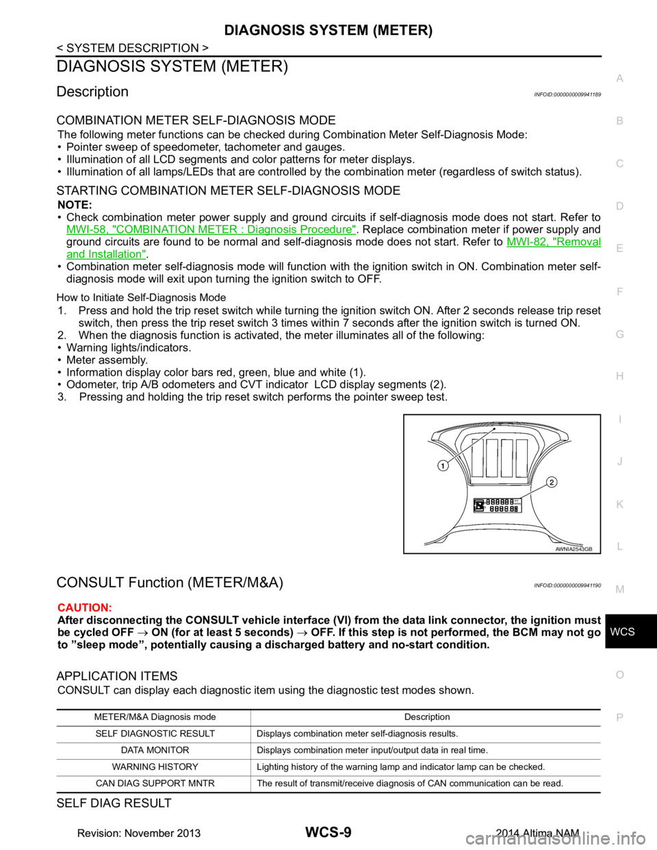
1. Press and hold the trip reset switch while turning the ignition switch ON. After 2 seconds release trip reset
switch, then press the trip reset switch 3 times withi n 7 seconds after the ignition switch is turned ON.
2. When the diagnosis function is activated, the meter illuminates all of the following:
• Warning lights/indicators.
• Meter assembly.
• Information display color bars red, green, blue and white (1).
• Odometer, trip A/B odometers and CVT indicator LCD display segments (2).
3. Pressing and holding the trip reset switch performs the pointer sweep test.
CONSULT Function (METER/M&A)INFOID:0000000009941190
CAUTION:
After disconnecting the CONSULT vehicle interface (VI) from the data link connector, the ignition must
be cycled OFF → ON (for at least 5 seconds) → OFF. If this step is not performed, the BCM may not go
to ”sleep mode”, potentiall y causing a discharged battery and no-start condition.
APPLICATION ITEMS
CONSULT can display each diagnostic item using the diagnostic test modes shown.
SELF DIAG RESULT
AWNIA2543GB
METER/M&A Diagnosis mode Description
SELF DIAGNOSTIC RESULT Displays combination meter self-diagnosis results. DATA MONITOR Displays combination meter input/output data in real time.
WARNING HISTORY Lighting history of the warning lamp and indicator lamp can be checked.
CAN DIAG SUPPORT MNTR The result of transmit/receive diagnosis of CAN communication can be read.
Revision: November 20132014 Altima NAMRevision: November 20132014 Altima NAM