2014 NISSAN TEANA fuel fill door release
[x] Cancel search: fuel fill door releasePage 773 of 4801

DLK-5
C
D E
F
G H
I
J
L
M A
B
DLK
N
O P
REAR DOOR LOCK ..............................................
..
204
REAR DOOR LOCK : Exploded View ...................204
REAR DOOR LOCK : Removal and Installation ...205
TRUNK LID ..................................................... ..206
TRUNK LID ASSEMBLY ...... ...................................206
TRUNK LID ASSEMBLY : Exploded View .......... ..206
TRUNK LID ASSEMBLY : Removal and Installa-
tion ...................................................................... ..
206
TRUNK LID ASSEMBLY : Adjustment ................ ..208
TRUNK LID HINGE ............................................... ..209
TRUNK LID HINGE : Removal and Installation ....209
TORSION BAR ...................................................... ..210
TORSION BAR : Removal and Installation ...........210
TRUNK LAMP SWITCH AND TRUNK RELEASE
SOLENOID ............................................................ ..
210
TRUNK LAMP SWITCH AND TRUNK RELEASE
SOLENOID : Removal and Installation .................
210
EMERGENCY LEVER ........................................... ..211
EMERGENCY LEVER : Removal and Installation ..211
TRUNK LID STRIKER ........................................... ..211
TRUNK LID STRIKER : Removal and Installation ..211
FUEL FILLER LID OPENER ............................213
Exploded View .................................................... ..213
FUEL FILLER LID ................................................. ..213
FUEL FILLER LID : Removal and Installation .......213
FUEL FILLER OPENER CABLE ........................... ..214
FUEL FILLER OPENER CABLE : Removal and
Installation ........................................................... ..
214
FUEL FILLER LID LOCK ...................................... ..215
FUEL FILLER LID LOCK : Removal and Installa-
tion ...................................................................... ..
215
KEY CYLINDER ...............................................217
GLOVE BOX LID KEY CYLINDER ....................... ..217
GLOVE BOX LID KEY CYLINDER : Removal and
Installation ........................................................... ..
217
SEATBACK LOCK KEY CYLINDER .................... ..218
SEATBACK LOCK KEY CYLINDER : Removal
and Installation .................................................... ..
218
DOOR SWITCH ................................................219
Removal and Installation .......................................219
INSIDE KEY ANTENNA ..................................220
CONSOLE .............................................................. ..220
CONSOLE : Removal and Installation ...................220
LUGGAGE ROOM ................................................. ..220
LUGGAGE ROOM : Removal and Installation ......220
OUTSIDE KEY ANTENNA ..............................221
DRIVER SIDE ......................................................... ..221
DRIVER SIDE : Removal and Installation .............221
PASSENGER SIDE ..................................................221
PASSENGER SIDE : Removal and Installation .. ..221
REAR BUMPER ..................................................... ..221
REAR BUMPER : Removal and Installation ..........221
DOOR REQUEST SWITCH ............................222
DRIVER SIDE ......................................................... ..222
DRIVER SIDE : Removal and Installation .............222
PASSENGER SIDE ..................................................222
PASSENGER SIDE : Removal and Installation .. ..222
INTELLIGENT KEY WARNING BUZZER .......223
Removal and Installation .......................................223
REMOTE KEYLESS ENTRY RECEIVER .......224
Removal and Installation .......................................224
INTELLIGENT KEY BATTERY .......................225
Removal and Installation .......................................225
TRUNK LID OPENER CANCEL SWITCH ......226
Removal and Installation .......................................226
TRUNK LID OPENER SWITCH ......................227
Removal and Installation .......................................227
TRUNK OPENER REQUEST SWITCH ..........228
Removal and Installation .......................................228
UNIT DISASSEMBLY AND ASSEMBLY ..229
FRONT DOOR .................................................229
Exploded View ..................................................... ..229
Disassembly and Assembly ...................................229
REAR DOOR ...................................................231
Exploded View .......................................................231
Disassembly and Assembly ...................................231
Revision: November 20132014 Altima NAMRevision: November 20132014 Altima NAM
Page 943 of 4801

HOOD
DLK-175
< REMOVAL AND INSTALLATION >
C
D E
F
G H
I
J
L
M A
B
DLK
N
O P
• After installation, perform hood assem bly adjustment procedure. Refer to DLK-172, "HOOD ASSEM-
BLY : Adjustment".
HOOD SUPPORT ROD
HOOD SUPPORT ROD : Removal and InstallationINFOID:0000000009461926
REMOVAL
1. Support hood assembly using a suitable tool.
WARNING:
Bodily injury may occur if hood assembly is not supported properly when removing hood support
rod.
2. Rotate and remove hood support rod from grommet.
3. Release tab and remove grommet from hood hinge, if necessary.
INSTALLATION
Installation is in the reverse order of removal.
HOOD LOCK CONTROL
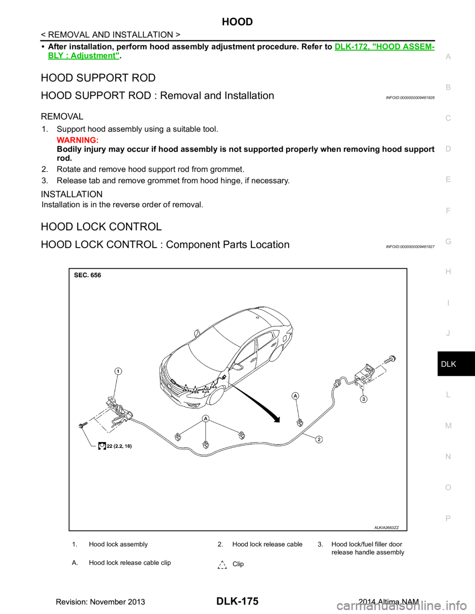
HOOD LOCK CONTROL : Co mponent Parts LocationINFOID:0000000009461927
1. Hood lock assembly 2. Hood lock release cable 3. Hood lock/fuel filler door
release handle assembly
A. Hood lock release cable clip Clip
ALKIA2663ZZ
Revision: November 20132014 Altima NAMRevision: November 20132014 Altima NAM
Page 944 of 4801

DLK-176
< REMOVAL AND INSTALLATION >
HOOD
HOOD LOCK CONTROL : Re moval and Installation
INFOID:0000000009461928
REMOVAL
1. Release the radiator core support upper cover clips, then remove the radiator core support upper cover.
2. Remove the hoodledge finisher clips (LH), then remove the hoodledge finisher LH.
3. Disconnect the hood switch harness connector (A) (if equipped). : Front
4. Remove the hood lock assembly bolts ( ).
5. Disconnect the hood lock release cable from t he hood lock assembly and unclip from the hoodledge.
6. Remove the fender protector LH. Refer to EXT-26, "FENDER PROTECTOR : Removal and Installation"
.
7. Remove the bolts (A), then separate the hood lock/fuel filler door release handle assembly (1) from the hood lock release cable
(3) and fuel filler door release cable (2).
8. Remove the grommet from the upper dash assembly and pull the hood lock release cable into the passen- ger compartment.
CAUTION:
While pulling, be careful no t to damage (peel) the outsid e of the hood lock release cable.
INSTALLATION
1. Pull the hood lock release cable through the upper dash assembly into the engine compartment.
CAUTION:
Be careful not to bend the cable too much , keep the radius 100 mm (3.94 in) or more.
ALKIA2664ZZ
ALKIA0027GB
ALKIA2665ZZ
Revision: November 20132014 Altima NAMRevision: November 20132014 Altima NAM
Page 945 of 4801

HOOD
DLK-177
< REMOVAL AND INSTALLATION >
C
D E
F
G H
I
J
L
M A
B
DLK
N
O P
2. Attach the hood lock release cable (3) and the fuel filler door release cable (2) to the hood lock/fuel filler door release handle
assembly (1).
3. Place hood lock/fuel filler door release handle assembly in posi- tion and retain with bolts (A).
4. Check that the cable is not offset from the center of the grommet
and seat the grommet into the upper dash hole.
NOTE:
Make sure that the marked area (A) of the cable is located as
shown after mounting grommet to dash upper assembly.
Apply sealant around the grommet at * mark.
5. Position the hood lock release cable and clip it into place.
6. Install the hoodledge finisher (LH) and retain with clips.
7. Connect the hood lock release cable to the hood lock assembly.
8. Install the fender protector (LH). Refer to EXT-26, "FENDER PROTECTOR : Removal and Installation"
.
9. Perform hood fitting adjustment. Refer to DLK-172, "HOOD ASSEMBLY : Adjustment"
.
10. Perform the hood lock control inspection.
INSPECTION
NOTE:
If the hood lock release cable is bent or deformed, replace it.
1. Check that the secondary latch is properly engaged wi th the secondary striker and meets specification
provided (B) with hood's own weight.
ALKIA2665ZZ
ALKIA2139ZZ
PIIB5802E
PIIB5794E
Revision: November 20132014 Altima NAMRevision: November 20132014 Altima NAM
Page 2947 of 4801

INSTRUMENT LOWER PANEL LHIP-21
< REMOVAL AND INSTALLATION >
C
D E
F
G H
I
K L
M A
B
IP
N
O P
INSTRUMENT LOWER PANEL LH
Removal and InstallationINFOID:0000000009461386
REMOVAL
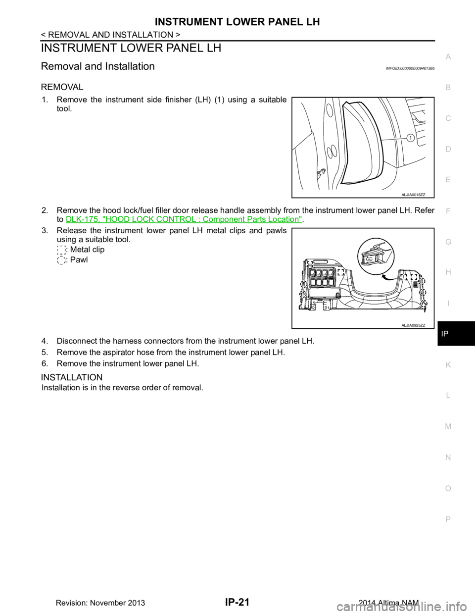
1. Remove the instrument side finisher (LH) (1) using a suitable tool.
2. Remove the hood lock/fuel filler door release handle assembly from the instrument lower panel LH. Refer to DLK-175, "HOOD LOCK CONTRO L : Component Parts Location"
.
3. Release the instrument lower panel LH metal clips and pawls using a suitable tool.
: Metal clip
: Pawl
4. Disconnect the harness connectors from the instrument lower panel LH.
5. Remove the aspirator hose from the instrument lower panel LH.
6. Remove the instrument lower panel LH.
INSTALLATION
Installation is in the reverse order of removal.
ALJIA0018ZZ
ALJIA0925ZZ
Revision: November 20132014 Altima NAM
Page 3268 of 4801

MWI
SYSTEMMWI-13
< SYSTEM DESCRIPTION >
C
D E
F
G H
I
J
K L
M B
A
O P
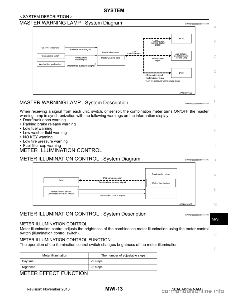
MASTER WARNING LAMP : System DiagramINFOID:0000000009461683
MASTER WARNING LAMP : System DescriptionINFOID:0000000009461684
When receiving a signal from each unit, switch, or s ensor, the combination meter turns ON/OFF the master
warning lamp in synchronization with the following warnings on the information display:
• Door/trunk open warning
• Parking brake release warning
• Low fuel warning
• Low washer fluid warning
• NO KEY warning
• Low tire pressure warning
• Fuel filler cap warning
METER ILLUMINATION CONTROL
METER ILLUMINATION CONTROL : System DiagramINFOID:0000000009461685
METER ILLUMINATION CONTROL : System DescriptionINFOID:0000000009461686
METER ILLUMINATION CONTROL
Meter illumination control adjusts the brightness of the combination meter illumination using the meter control
switch (illumination control switch).
METER ILLUMINATION CONTROL FUNCTION
The operation of the illumination control switch changes brightness of the meter illumination.
METER EFFECT FUNCTION
AWNIA2975GB
AWNIA2548GB
Meter illumination The number of adjustable steps
Daytime 22 steps
Nighttime 22 steps
Revision: November 20132014 Altima NAMRevision: November 20132014 Altima NAM
Page 3271 of 4801

MWI-16
< SYSTEM DESCRIPTION >
SYSTEM
The LOOSE FUEL CAP message will display in the information display when the fuel-filler cap is not tightened
correctly. The message will turn off as soon as the EC M detects the fuel-filler cap is properly tightened. The
ECM provides a loose fuel cap signal to the combination meter via CAN communication.
LOW TIRE PRESSURE WARNING
This warning appears when the BCM detects low inflati on pressure or a system malfunction. The BCM sends
a signal to the combination meter via CAN communication to illuminate the low tire pressure warning lamp. In
addition, a warning message will be displayed in the vehicle information display.
DOOR OPEN WARNING
This warning appears when the ignition switch is ON and the door is open. The BCM receives a door switch
signal from the door open door switch. The BCM sends t he door switch signal to the combination meter via
CAN communication lines.
TRUNK OPEN WARNING
This warning appears when the ignition switch is ON and the trunk is opened. The BCM receives a trunk lamp
switch signal from the trunk lamp switch. The BCM s ends the trunk lamp switch signal to the combination
meter via CAN communication.
LOW FUEL WARNING
This warning appears when the fuel level in the fuel tank is less than approximately 4 US gal (15 L, 3.3 Imp
gal). A variable resistor signal is supplied to the combi nation meter from the fuel level sensor unit to determine
the amount of fuel in the fuel tank.
LOW WINDSHIELD WASHER FLUID WARNING
When the windshield washer fluid level is low, the was her fluid level switch provides a ground signal to the
combination meter and the warning is displayed. Once fluid is added, the switch opens and the warning is no
longer displayed.
RELEASE PARKING BRAKE WARNING
When the parking brake is applied, the parking brake switch provides a ground signal to the combination
meter. When the vehicle speed is greater than 4 MPH (7 km/h), the message is displayed and the warning
chime sounds.
SHIFT POSITION INDICATOR
Displays the position of the shift selector based on signals received from TCM via CAN communication.
LOW OIL PRESSURE WARNING
The low oil pressure warning appears in the information display when the combination meter receives a low
engine oil pressure signal from the ECM via CAN communication.
WARNING CHECK INDICATION
The combination meter can cause an interrupt on the information display to indicate a warning, based on sig-
nals received from each unit and switch.
Refer to Owner’s Manual for additional information display items.
COMPASS
COMPASS : DescriptionINFOID:0000000009461691
DESCRIPTION
With the ignition switch in the ON position, and the mode (N) switch
ON, the compass display will indicate the direction the vehicle is
heading.
Vehicle direction is displayed as follows:
• N: north
• E: east
• S: south
•W: west
LKIA0447E
Revision: November 20132014 Altima NAMRevision: November 20132014 Altima NAM