Page 4124 of 4801

POWER SUPPLY AND GROUND CIRCUITST-21
< DTC/CIRCUIT DIAGNOSIS >
C
D E
F
H I
J
K L
M A
B
ST
N
O P
DTC/CIRCUIT DIAGNOSIS
POWER SUPPLY AND GROUND CIRCUIT
A/C AUTO AMP.
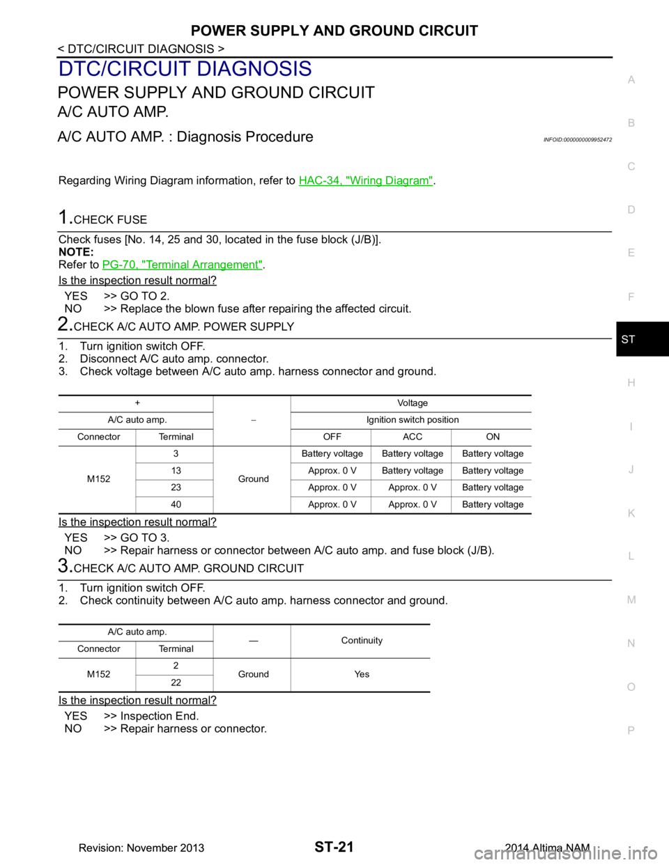
A/C AUTO AMP. : Diagnosis ProcedureINFOID:0000000009952472
Regarding Wiring Diagram information, refer to HAC-34, "Wiring Diagram".
1.CHECK FUSE
Check fuses [No. 14, 25 and 30, loca ted in the fuse block (J/B)].
NOTE:
Refer to PG-70, "Terminal Arrangement"
.
Is the inspection result normal?
YES >> GO TO 2.
NO >> Replace the blown fuse after repairing the affected circuit.
2.CHECK A/C AUTO AMP. POWER SUPPLY
1. Turn ignition switch OFF.
2. Disconnect A/C auto amp. connector.
3. Check voltage between A/C auto amp. harness connector and ground.
Is the inspection result normal?
YES >> GO TO 3.
NO >> Repair harness or connector between A/C auto amp. and fuse block (J/B).
3.CHECK A/C AUTO AMP. GROUND CIRCUIT
1. Turn ignition switch OFF.
2. Check continuity between A/C aut o amp. harness connector and ground.
Is the inspection result normal?
YES >> Inspection End.
NO >> Repair harness or connector.
+
− Voltag e
A/C auto amp. Ignition switch position
Connector Terminal OFF ACC ON
M152 3
GroundBattery voltage Battery voltage Battery voltage
13 Approx. 0 V Battery voltage Battery voltage
23 Approx. 0 V Approx. 0 V Battery voltage
40 Approx. 0 V Approx. 0 V Battery voltage
A/C auto amp. — Continuity
Connector Terminal
M152 2
Ground Yes
22
Revision: November 20132014 Altima NAMRevision: November 20132014 Altima NAM
Page 4667 of 4801

WCS
POWER SUPPLY AND GROUND CIRCUITWCS-25
< DTC/CIRCUIT DIAGNOSIS >
C
D E
F
G H
I
J
K L
M B
A
O P
DTC/CIRCUIT DIAGNOSIS
POWER SUPPLY AND GROUND CIRCUIT
COMBINATION METER
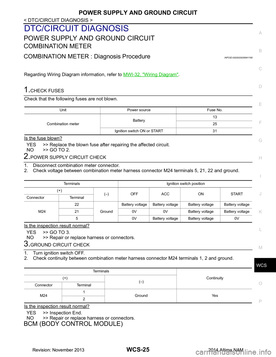
COMBINATION METER : Diagnosis ProcedureINFOID:0000000009941198
Regarding Wiring Diagram information, refer to MWI-32, "Wiring Diagram".
1.CHECK FUSES
Check that the following fuses are not blown.
Is the fuse blown?
YES >> Replace the blown fuse after repairing the affected circuit.
NO >> GO TO 2.
2.POWER SUPPLY CIRCUIT CHECK
1. Disconnect combination meter connector.
2. Check voltage between combination meter harnes s connector M24 terminals 5, 21, 22 and ground.
Is the inspection result normal?
YES >> GO TO 3.
NO >> Repair or replace harness or connectors.
3.GROUND CIRCUIT CHECK
1. Turn ignition switch OFF.
2. Check continuity between combination mete r harness connector M24 terminals 1, 2 and ground.
Is the inspection result normal?
YES >> Inspection End.
NO >> Repair or replace harness or connectors.
BCM (BODY CONTROL MODULE)
Unit Power source Fuse No.
Combination meter Battery 13
25
Ignition switch ON or START 31
Terminals Ignition switch position
(+) (–) OFF ACC ON START
Connector Terminal
M24 22
GroundBattery voltage Battery voltage Battery voltage Battery voltage
21 0V 0V Battery voltage Battery voltage 5 0V Battery voltage Battery voltage 0V
Te r m i n a l s Continuity
(+)
(–)
Connector Terminal
M24 1
Ground Yes
2
Revision: November 20132014 Altima NAMRevision: November 20132014 Altima NAM
Page 4768 of 4801
WIPER AND WASHER FUSEWW-33
< DTC/CIRCUIT DIAGNOSIS >
C
D E
F
G H
I
J
K
M A
B
WW
N
O P
DTC/CIRCUIT DIAGNOSIS
WIPER AND WASHER FUSE
DescriptionINFOID:0000000009464612
Fuse list
Diagnosis ProcedureINFOID:0000000009464613
1. CHECK FUSES
Check that the following fuses are not blown.
Is the fuse blown?
YES >> Replace the blown fuse after repairing the affected circuit.
NO >> Inspection End.
Unit Location Fuse No. Capacity
Front wiper motor IPDM E/R 41 30 A
Front washer motor IPDM E/R 50 10 A
Unit Location Fuse No. Capacity
Front wiper motor IPDM E/R 41 30 A
Front washer motor IPDM E/R 50 10 A
Revision: November 20132014 Altima NAMRevision: November 20132014 Altima NAM
Page:
< prev 1-8 9-16 17-24