2014 NISSAN TEANA high beam
[x] Cancel search: high beamPage 48 of 4801
![NISSAN TEANA 2014 Service Manual
BCS
BCM (BODY CONTROL MODULE)BCS-33
< ECU DIAGNOSIS INFORMATION > [BCM]
C
D E
F
G H
I
J
K L
B
A
O P
N
FR WASHER SW
Front washer switch OFF Off
Front washer switch ON On
FR WIPER LOW Front wiper sw NISSAN TEANA 2014 Service Manual
BCS
BCM (BODY CONTROL MODULE)BCS-33
< ECU DIAGNOSIS INFORMATION > [BCM]
C
D E
F
G H
I
J
K L
B
A
O P
N
FR WASHER SW
Front washer switch OFF Off
Front washer switch ON On
FR WIPER LOW Front wiper sw](/manual-img/5/57390/w960_57390-47.png)
BCS
BCM (BODY CONTROL MODULE)BCS-33
< ECU DIAGNOSIS INFORMATION > [BCM]
C
D E
F
G H
I
J
K L
B
A
O P
N
FR WASHER SW
Front washer switch OFF Off
Front washer switch ON On
FR WIPER LOW Front wiper switch OFF Off
Front wiper switch LO On
FR WIPER HI Front wiper switch OFF Off
Front wiper switch HI On
FR WIPER INT Front wiper switch OFF Off
Front wiper switch INT On
FR WIPER STOP Any position other than front wiper stop position Off
Front wiper stop position On
HAZARD SW When hazard switch is not pressed Off
When hazard switch is pressed On
HEAD LAMP SW 1 Headlamp switch OFF Off
Headlamp switch 1st On
HEAD LAMP SW 2 Headlamp switch OFF Off
Headlamp switch 1st On
HI BEAM SW High beam switch OFF Off
High beam switch HI On
ID AUTHENT CANCEL TIMER When I-Key authentication is OFF. STOP
ID OK FLAG Ignition switch ACC or ON Reset
Ignition switch OFF Set
ID REGST FL1 ID registration of front left tire incomplete YET
ID registration of front left tire complete DONE
ID REGST FR1 ID registration of front right tire incomplete YET
ID registration of front right tire complete DONE
ID REGST RL1 ID registration of rear left tire incomplete YET
ID registration of rear left tire complete DONE
ID REGST RR1 ID registration of rear
right tire incomplete YET
ID registration of rear right tire complete DONE
IGN RLY1 F/B Ignition switch OFF or ACC Off
Ignition switch ON On
INT VOLUME Wiper intermittent dial is in a dial position 1 - 7 1 - 7
I-KEY OK FLAG I-Key OFF Key OFF
I-Key ON Key ON
KEY CYL LK-SW Door key cylinder LOCK position Off
Door key cylinder other than LOCK position On
KEY CYL UN-SW Door key cylinder UNLOCK position Off
Door key cylinder other than UNLOCK position On
OPTI SEN (DTCT) Bright outside of the vehicle Close to 5V
Dark outside of the vehicle Close to 0V
OPTI SEN (FILT) Bright outside of the vehicle Close to 5V
Dark outside of the vehicle Close to 0V
PA S S I N G S W Other than lighting switch PASS Off
Lighting switch PASS On
Monitor Item Condition Value/Status
Revision: November 20132014 Altima NAMRevision: November 20132014 Altima NAM
Page 2268 of 4801

EXL-2
ECU DIAGNOSIS INFORMATION ..............26
BCM, IPDM E/R .............................................. ...26
List of ECU Reference ......................................... ...26
WIRING DIAGRAM .....................................27
HEADLAMP .................................................... ...27
Wiring Diagram - Halogen ................................... ...27
Wiring Diagram - Xenon .........................................33
DAYTIME LIGHT SYSTEM ................................39
Wiring Diagram .................................................... ...39
AUTO LIGHT SYSTEM ......................................47
Wiring Diagram .................................................... ...47
FRONT FOG LAMP ...........................................54
Wiring Diagram .................................................... ...54
TURN SIGNAL AND HAZARD WARNING
LAMPS ............................................................ ...
60
Wiring Diagram .................................................... ...60
PARKING, LICENSE PLATE AND TAIL
LAMPS ............................................................ ...
68
Wiring Diagram .................................................... ...68
STOP LAMP ......................................................76
Wiring Diagram .................................................... ...76
BACK-UP LAMP ................................................79
Wiring Diagram .................................................... ...79
BASIC INSPECTION ...................................86
DIAGNOSIS AND REPAIR WORKFLOW ...... ...86
Work Flow ............................................................ ...86
DTC/CIRCUIT DIAGNOSIS ...................... ...89
POWER SUPPLY AND GROUND CIRCUIT .. ...89
BCM (BODY CONTROL MODULE) ...................... ...89
BCM (BODY CONTROL MODULE) : Diagnosis
Procedure ............................................................ ...
89
IPDM E/R (INTELLIGENT POWER DISTRIBU-
TION MODULE ENGINE ROOM) .......................... ...
89
IPDM E/R (INTELLIGENT POWER DISTRIBU-
TION MODULE ENGINE ROOM) : Diagnosis Pro-
cedure .................................................................. ...
89
HEADLAMP (HI) CIRCUIT ................................91
Description ........................................................... ...91
Component Function Check ...................................91
Diagnosis Procedure ..............................................91
HEADLAMP (LO) CIRCUIT ...............................93
HEADLAMP (HALOGEN) ...................................... ...93
HEADLAMP (HALOGEN) : Description ..................93
HEADLAMP (HALOGEN) : Component Function
Check ................................................................... ...
93
HEADLAMP (HALOGEN) : Diagnosis Procedure ...93
HEADLAMP (XENON) ........................................... ...94
HEADLAMP (XENON) : Description .......................94
HEADLAMP (XENON) : Component Function
Check ................................................................... ...
94
HEADLAMP (XENON) : Diagnosis Procedure ........95
XENON HEADLAMP .........................................97
Description ........................................................... ...97
Diagnosis Procedure ...............................................97
DAYTIME LIGHT RELAY CIRCUIT ..................98
Description ........................................................... ...98
Diagnosis Procedure ...............................................98
Component Inspection ............................................99
FRONT FOG LAMP CIRCUIT ..........................101
Description ........................................................... .101
Component Function Check .................................101
Diagnosis Procedure .............................................101
PARKING LAMP CIRCUIT ...............................103
Description ........................................................... .103
Component Function Check .................................103
Diagnosis Procedure .............................................103
TURN SIGNAL LAMP CIRCUIT .......................106
Description ........................................................... .106
Component Function Check .................................106
Diagnosis Procedure .............................................106
OPTICAL SENSOR ..........................................110
Description ........................................................... .110
Component Function Check .................................110
Diagnosis Procedure .............................................110
HAZARD SWITCH .......................................... ..112
Component Function Check ................................ .112
Diagnosis Procedure .............................................112
SYMPTOM DIAGNOSIS ...........................114
EXTERIOR LIGHTING SYSTEM SYMPTOMS ..114
Symptom Table .................................................... .114
NORMAL OPERATING CONDITION ...............116
Description ........................................................... .116
BOTH SIDE HEADLAMPS DO NOT SWITCH
TO HIGH BEAM .............................................. ..
117
Description ........................................................... .117
Diagnosis Procedure .............................................117
DAYTIME LIGHT SYSTEM INOPERATIVE .....118
Description ........................................................... .118
Diagnosis Procedure .............................................118
BOTH SIDE HEADLAMPS (LO) ARE NOT
TURNED ON ................................................... ..
119
Revision: November 20132014 Altima NAMRevision: November 20132014 Altima NAM
Page 2275 of 4801
SYSTEMEXL-9
< SYSTEM DESCRIPTION >
C
D E
F
G H
I
J
K
M A
B
EXL
N
O P
SYSTEM
HEADLAMP SYSTEM
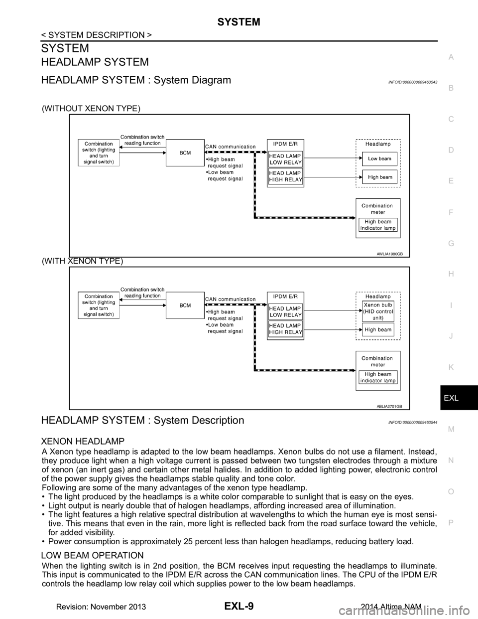
HEADLAMP SYSTEM : System DiagramINFOID:0000000009463543
(WITHOUT XENON TYPE)
(WITH XENON TYPE)
HEADLAMP SYSTEM : System DescriptionINFOID:0000000009463544
XENON HEADLAMP
A Xenon type headlamp is adapted to the low beam headlamps. Xenon bulbs do not use a filament. Instead,
they produce light when a high voltage current is pa ssed between two tungsten electrodes through a mixture
of xenon (an inert gas) and certain other metal halides. In addition to added lighting power, electronic control
of the power supply gives the headlamps stable quality and tone color.
Following are some of the many advantages of the xenon type headlamp.
• The light produced by the headlamps is a white color comparable to sunlight that is easy on the eyes.
• Light output is nearly double that of halogen headl amps, affording increased area of illumination.
• The light features a high relative spectral distributi on at wavelengths to which the human eye is most sensi-
tive. This means that even in the rain, more light is reflected back from the road surface toward the vehicle,
for added visibility.
• Power consumption is approximately 25 percent less than halogen headlamps, reducing battery load.
LOW BEAM OPERATION
When the lighting switch is in 2nd position, the BCM receives input requesting the headlamps to illuminate.
This input is communicated to the IPDM E/R across the CAN communication lines. The CPU of the IPDM E/R
controls the headlamp low relay coil which supplies power to the low beam headlamps.
AWLIA1980GB
ABLIA2701GB
Revision: November 20132014 Altima NAMRevision: November 20132014 Altima NAM
Page 2276 of 4801
EXL-10
< SYSTEM DESCRIPTION >
SYSTEM
HIGH BEAM OPERATION/FLASH-TO-PASS OPERATION
With the lighting switch in the 2nd position and placed in HIGH position, the BCM receives input requesting the
headlamp high beams to illuminate. The flash to pass f eature can be used any time and also sends a signal to
the BCM. This input is communicated to the IPDM E/R across the CAN communication lines. The CPU of the
combination meter controls the ON/OFF status off the HIGH BEAM indicator. The CPU of the IPDM E/R con-
trols the headlamp high relay coil which supplies power to the high beam headlamps.
The combination meter receives a high beam request signal (ON) through the CAN communication lines and
turns the high beam indicator lamp ON.
EXTERIOR LAMP BATTERY SAVER CONTROL
With the combination switch (lighting and turn signal switch) in the 2nd position and the ignition switch is
turned from ON or ACC to OFF, the battery saver feature is activated.
Under this condition, the headlamps remain illuminated fo r a period of time, unless the lighting switch position
is changed. If the lighting switch position is changed, then the headlamps are turned off.
AUTO LIGHT SYSTEM
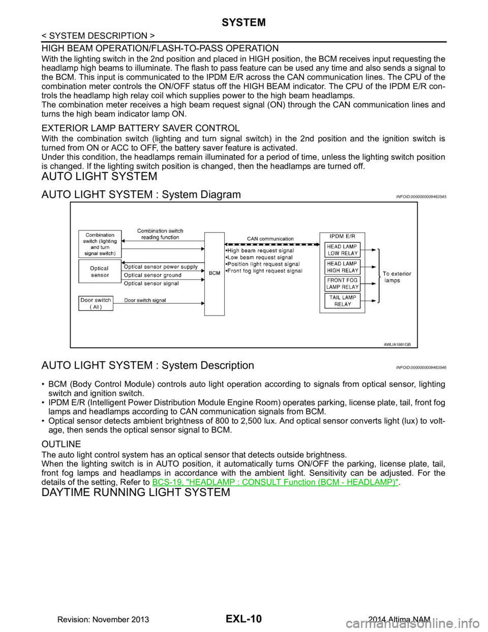
AUTO LIGHT SYSTEM : System DiagramINFOID:0000000009463545
AUTO LIGHT SYSTEM : System DescriptionINFOID:0000000009463546
• BCM (Body Control Module) controls auto light operati on according to signals from optical sensor, lighting
switch and ignition switch.
• IPDM E/R (Intelligent Power Distribution Module Engine R oom) operates parking, license plate, tail, front fog
lamps and headlamps according to CAN communication signals from BCM.
• Optical sensor detects ambient brightness of 800 to 2,500 lux. And optical sensor converts light (lux) to volt-
age, then sends the optical sensor signal to BCM.
OUTLINE
The auto light control system has an optical sensor that detects outside brightness.
When the lighting switch is in AUTO position, it autom atically turns ON/OFF the parking, license plate, tail,
front fog lamps and headlamps in accordance with the am bient light. Sensitivity can be adjusted. For the
details of the setting, Refer to BCS-19, "HEADLAMP : CONSULT Function (BCM - HEADLAMP)"
.
DAYTIME RUNNING LIGHT SYSTEM
AWLIA1981GB
Revision: November 20132014 Altima NAMRevision: November 20132014 Altima NAM
Page 2290 of 4801

EXL-24
< SYSTEM DESCRIPTION >
DIAGNOSIS SYSTEM (IPDM E/R)
APPLICATION ITEM
CONSULT performs the following functions via CAN communication with IPDM E/R.
ECU IDENTIFICATION
The IPDM E/R part number is displayed.
SELF DIAGNOSTIC RESULT
Refer to PCS-20, "DTC Index".
DATA MONITOR
Direct Diagnostic Mode Description
Ecu Identification The IPDM E/R part number is displayed.
Self Diagnostic Result The IPDM E/R self diagnostic results are displayed.
Data Monitor The IPDM E/R input/output data is displayed in real time.
Active Test The IPDM E/R activates outputs to test components.
CAN Diag Support Mntr The result of transmit/receive diagnosis of CAN communication is displayed.
Monitor Item [Unit] Main
Signals Description
MOTOR FAN REQ [%] ×Indicates cooling fan speed signal received from ECM on CAN communication
line
AC COMP REQ [On/Off] ×Indicates A/C compressor request signal received from ECM on CAN commu-
nication line
TAIL&CLR REQ [On/Off] ×Indicates position light request signal received from BCM on CAN communica-
tion line
HL LO REQ [On/Off] ×Indicates low beam request signal received from BCM on CAN communication
line
HL HI REQ [On/Off] ×Indicates high beam request signal received from BCM on CAN communication
line
FR FOG REQ [On/Off] ×Indicates front fog light request signal received from BCM on CAN communica-
tion line
FR WIP REQ [Stop/1LOW/Low/Hi] ×Indicates front wiper request signal received from BCM on CAN communication
line
WIP AUTO STOP [STOP P/ACT P] ×Indicates condition of front wiper auto stop signal
WIP PROT [Off/BLOCK] ×Indicates condition of front wiper fail-safe operation
IGN RLY1 -REQ [On/Off] Indicates ignition switch ON signal received from BCM on CAN communication
line
IGN RLY [On/Off] ×Indicates condition of ignition relay
PUSH SW [On/Off] Indicates condition of push-button ignition switch
INTER/NP SW [On/Off] Indicates condition of CVT shift position
ST RLY CONT [On/Off] Indicates starter relay status signal received from BCM on CAN communication
line
IHBT RLY -REQ [On/Off] Indicates starter control relay signal received from BCM on CAN communication
line
ST/INHI RLY [Off/ ST /INHI] Indicates condition of starter relay and starter control relay
DETENT SW [On/Off] Indicates condition of CVT shift selector (park position switch)
DTRL REQ [Off] Indicates daytime light request signal received from BCM on CAN communica-
tion line
HOOD SW [On/Off] Indicates condition of hood switch
THFT HRN REQ [On/Off] Indicates theft warning horn request signal received from BCM on CAN commu-
nication line
Revision: November 20132014 Altima NAMRevision: November 20132014 Altima NAM
Page 2357 of 4801
HEADLAMP (HI) CIRCUITEXL-91
< DTC/CIRCUIT DIAGNOSIS >
C
D E
F
G H
I
J
K
M A
B
EXL
N
O P
HEADLAMP (HI) CIRCUIT
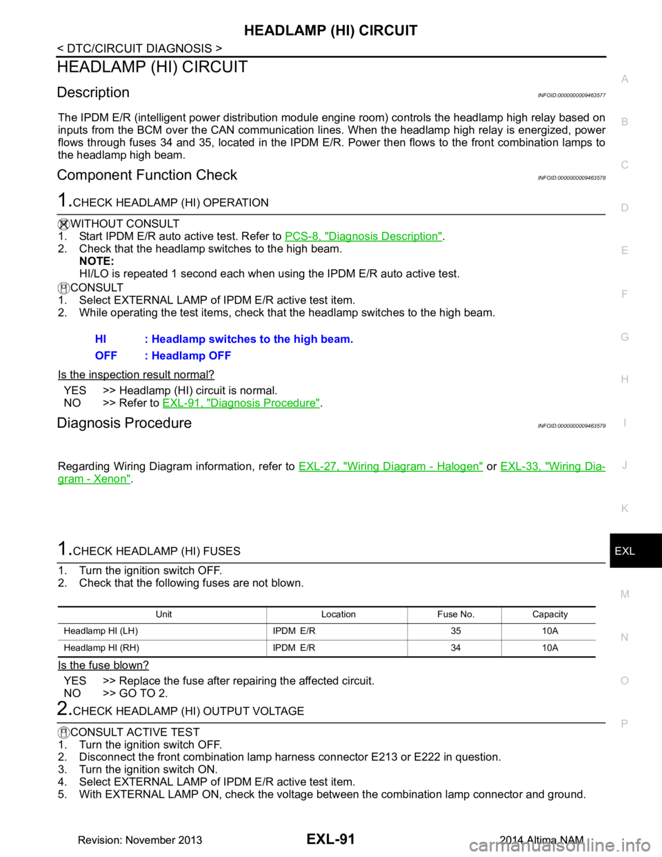
DescriptionINFOID:0000000009463577
The IPDM E/R (intelligent power distribution modul e engine room) controls the headlamp high relay based on
inputs from the BCM over the CAN communication li nes. When the headlamp high relay is energized, power
flows through fuses 34 and 35, located in the IPDM E/R. Power then flows to the front combination lamps to
the headlamp high beam.
Component Function CheckINFOID:0000000009463578
1.CHECK HEADLAMP (HI) OPERATION
WITHOUT CONSULT
1. Start IPDM E/R auto active test. Refer to PCS-8, "Diagnosis Description"
.
2. Check that the headlamp switches to the high beam. NOTE:
HI/LO is repeated 1 second each when using the IPDM E/R auto active test.
CONSULT
1. Select EXTERNAL LAMP of IP DM E/R active test item.
2. While operating the test items, check t hat the headlamp switches to the high beam.
Is the inspection result normal?
YES >> Headlamp (HI) circuit is normal.
NO >> Refer to EXL-91, "Diagnosis Procedure"
.
Diagnosis ProcedureINFOID:0000000009463579
Regarding Wiring Diagram information, refer to EXL-27, "Wiring Diagram - Halogen" or EXL-33, "Wiring Dia-
gram - Xenon".
1.CHECK HEADLAMP (HI) FUSES
1. Turn the ignition switch OFF.
2. Check that the following fuses are not blown.
Is the fuse blown?
YES >> Replace the fuse after repairing the affected circuit.
NO >> GO TO 2.
2.CHECK HEADLAMP (HI) OUTPUT VOLTAGE
CONSULT ACTIVE TEST
1. Turn the ignition switch OFF.
2. Disconnect the front combination lamp harness connector E213 or E222 in question.
3. Turn the ignition switch ON.
4. Select EXTERNAL LAMP of IP DM E/R active test item.
5. With EXTERNAL LAMP ON, check the voltage between the combination lamp connector and ground.
HI : Headlamp switches to the high beam.
OFF : Headlamp OFF
Unit Location Fuse No. Capacity
Headlamp HI (LH) IPDM E/R 35 10A
Headlamp HI (RH) IPDM E/R 34 10A
Revision: November 20132014 Altima NAMRevision: November 20132014 Altima NAM
Page 2380 of 4801
EXL-114
< SYMPTOM DIAGNOSIS >
EXTERIOR LIGHTING SYSTEM SYMPTOMS
SYMPTOM DIAGNOSIS
EXTERIOR LIGHTING SYSTEM SYMPTOMS
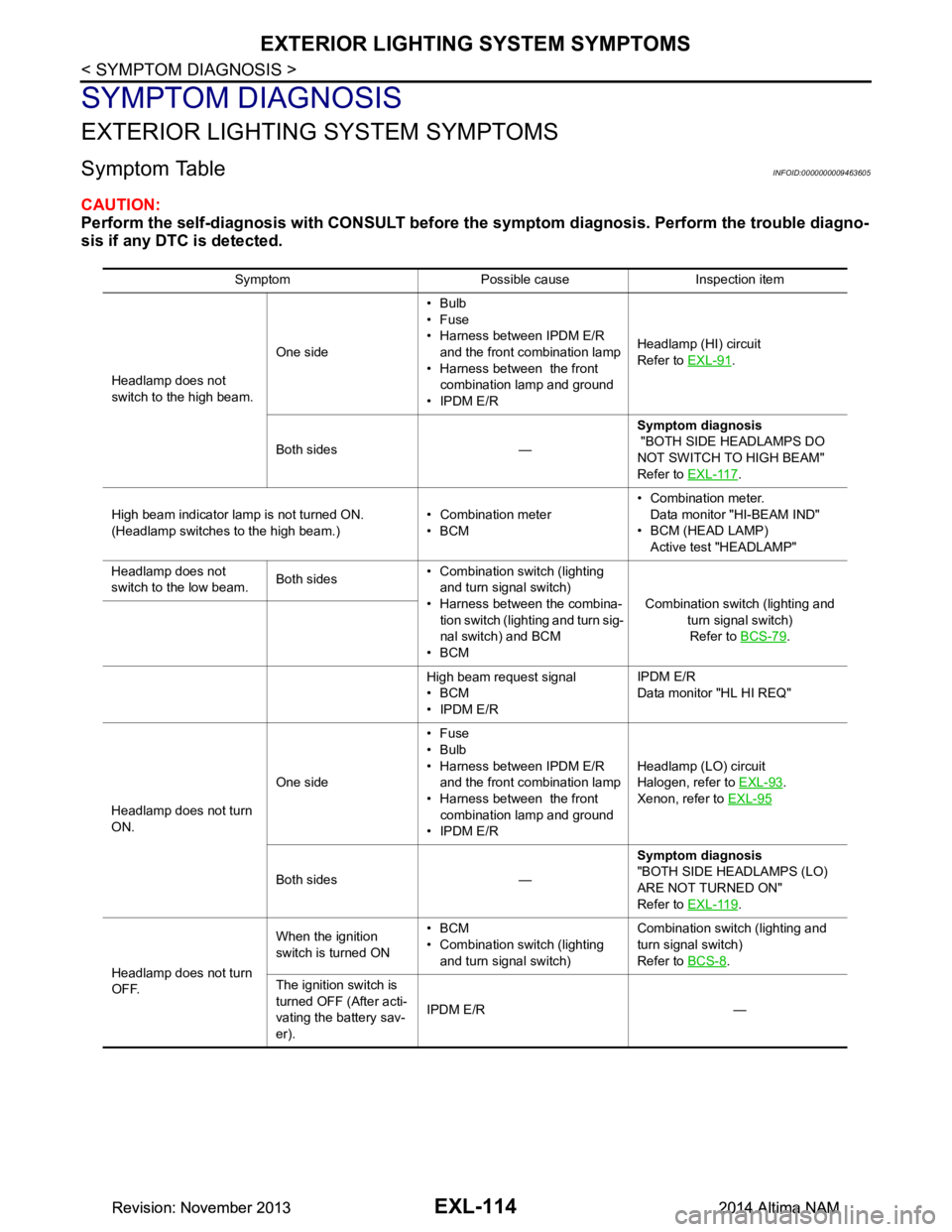
Symptom TableINFOID:0000000009463605
CAUTION:
Perform the self-diagnosis with CONSULT before th e symptom diagnosis. Perform the trouble diagno-
sis if any DTC is detected.
Symptom Possible cause Inspection item
Headlamp does not
switch to the high beam. One side•Bulb
•Fuse
• Harness between IPDM E/R and the front combination lamp
• Harness between the front combination lamp and ground
• IPDM E/R Headlamp (HI) circuit
Refer to EXL-91
.
Both sides — Symptom diagnosis
"BOTH SIDE HEADLAMPS DO
NOT SWITCH TO HIGH BEAM"
Refer to EXL-117
.
High beam indicator lamp is not turned ON.
(Headlamp switches to the high beam.) • Combination meter
•BCM • Combination meter.
Data monitor "HI-BEAM IND"
• BCM (HEAD LAMP) Active test "HEADLAMP"
Headlamp does not
switch to the low beam. Both sides• Combination switch (lighting
and turn signal switch)
• Harness between the combina- tion switch (lighting and turn sig-
nal switch) and BCM
•BCM Combination switch (lighting and
turn signal switch)Refer to BCS-79
.
High beam request signal
•BCM
• IPDM E/R IPDM E/R
Data monitor "HL HI REQ"
Headlamp does not turn
ON. One side•Fuse
•Bulb
• Harness between IPDM E/R and the front combination lamp
• Harness between the front combination lamp and ground
• IPDM E/R Headlamp (L
O) circuit
Halogen, refer to EXL-93
.
Xenon, refer to EXL-95
Both sides — Symptom diagnosis
"BOTH SIDE HEADLAMPS (LO)
ARE NOT TURNED ON"
Refer to EXL-119
.
Headlamp does not turn
OFF. When the ignition
switch is turned ON •BCM
• Combination switch (lighting and turn signal switch) Combination switch (lighting and
turn signal switch)
Refer to BCS-8
.
The ignition switch is
turned OFF (After acti-
vating the battery sav-
er). IPDM E/R —
Revision: November 20132014 Altima NAMRevision: November 20132014 Altima NAM
Page 2383 of 4801
BOTH SIDE HEADLAMPS DO NOT SWITCH TO HIGH BEAM
EXL-117
< SYMPTOM DIAGNOSIS >
C
D E
F
G H
I
J
K
M A
B
EXL
N
O P
BOTH SIDE HEADLAMPS DO NOT SWITCH TO HIGH BEAM
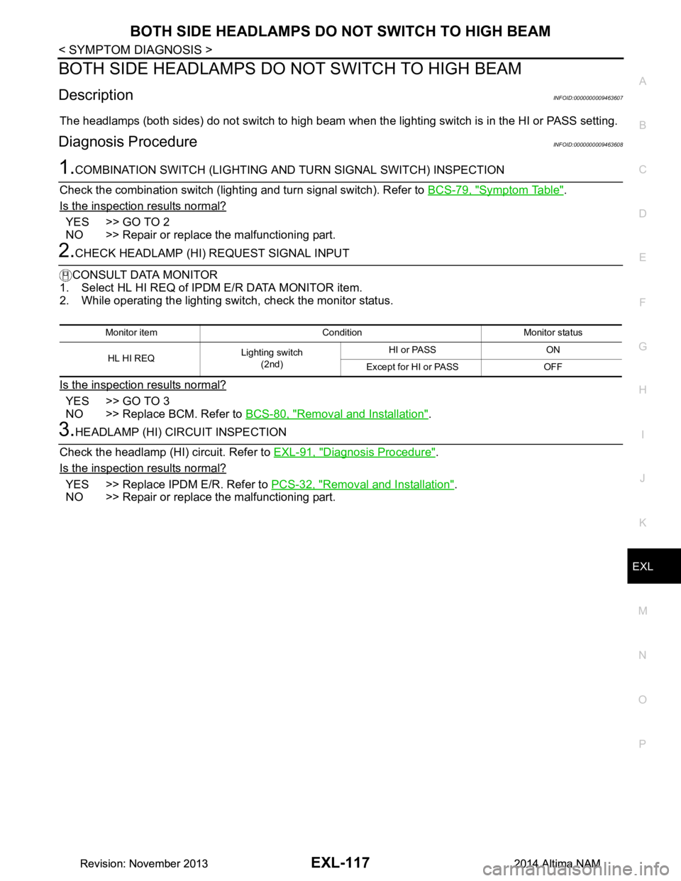
DescriptionINFOID:0000000009463607
The headlamps (both sides) do not switch to high beam when the lighting switch is in the HI or PASS setting.
Diagnosis ProcedureINFOID:0000000009463608
1.COMBINATION SWITCH (LIGHTING AND TURN SIGNAL SWITCH) INSPECTION
Check the combination switch (lighting and turn signal switch). Refer to BCS-79, "Symptom Table"
.
Is the inspection results normal?
YES >> GO TO 2
NO >> Repair or replace the malfunctioning part.
2.CHECK HEADLAMP (HI) REQUEST SIGNAL INPUT
CONSULT DATA MONITOR
1. Select HL HI REQ of IP DM E/R DATA MONITOR item.
2. While operating the lighting switch, check the monitor status.
Is the inspection results normal?
YES >> GO TO 3
NO >> Replace BCM. Refer to BCS-80, "Removal and Installation"
.
3.HEADLAMP (HI) CIRCUIT INSPECTION
Check the headlamp (HI) circuit. Refer to EXL-91, "Diagnosis Procedure"
.
Is the inspection results normal?
YES >> Replace IPDM E/R. Refer to PCS-32, "Removal and Installation".
NO >> Repair or replace the malfunctioning part.
Monitor item Condition Monitor status
HL HI REQ Lighting switch
(2nd) HI or PASS ON
Except for HI or PASS OFF
Revision: November 20132014 Altima NAMRevision: November 20132014 Altima NAM