2014 NISSAN TEANA driver seat adjustment
[x] Cancel search: driver seat adjustmentPage 773 of 4801

DLK-5
C
D E
F
G H
I
J
L
M A
B
DLK
N
O P
REAR DOOR LOCK ..............................................
..
204
REAR DOOR LOCK : Exploded View ...................204
REAR DOOR LOCK : Removal and Installation ...205
TRUNK LID ..................................................... ..206
TRUNK LID ASSEMBLY ...... ...................................206
TRUNK LID ASSEMBLY : Exploded View .......... ..206
TRUNK LID ASSEMBLY : Removal and Installa-
tion ...................................................................... ..
206
TRUNK LID ASSEMBLY : Adjustment ................ ..208
TRUNK LID HINGE ............................................... ..209
TRUNK LID HINGE : Removal and Installation ....209
TORSION BAR ...................................................... ..210
TORSION BAR : Removal and Installation ...........210
TRUNK LAMP SWITCH AND TRUNK RELEASE
SOLENOID ............................................................ ..
210
TRUNK LAMP SWITCH AND TRUNK RELEASE
SOLENOID : Removal and Installation .................
210
EMERGENCY LEVER ........................................... ..211
EMERGENCY LEVER : Removal and Installation ..211
TRUNK LID STRIKER ........................................... ..211
TRUNK LID STRIKER : Removal and Installation ..211
FUEL FILLER LID OPENER ............................213
Exploded View .................................................... ..213
FUEL FILLER LID ................................................. ..213
FUEL FILLER LID : Removal and Installation .......213
FUEL FILLER OPENER CABLE ........................... ..214
FUEL FILLER OPENER CABLE : Removal and
Installation ........................................................... ..
214
FUEL FILLER LID LOCK ...................................... ..215
FUEL FILLER LID LOCK : Removal and Installa-
tion ...................................................................... ..
215
KEY CYLINDER ...............................................217
GLOVE BOX LID KEY CYLINDER ....................... ..217
GLOVE BOX LID KEY CYLINDER : Removal and
Installation ........................................................... ..
217
SEATBACK LOCK KEY CYLINDER .................... ..218
SEATBACK LOCK KEY CYLINDER : Removal
and Installation .................................................... ..
218
DOOR SWITCH ................................................219
Removal and Installation .......................................219
INSIDE KEY ANTENNA ..................................220
CONSOLE .............................................................. ..220
CONSOLE : Removal and Installation ...................220
LUGGAGE ROOM ................................................. ..220
LUGGAGE ROOM : Removal and Installation ......220
OUTSIDE KEY ANTENNA ..............................221
DRIVER SIDE ......................................................... ..221
DRIVER SIDE : Removal and Installation .............221
PASSENGER SIDE ..................................................221
PASSENGER SIDE : Removal and Installation .. ..221
REAR BUMPER ..................................................... ..221
REAR BUMPER : Removal and Installation ..........221
DOOR REQUEST SWITCH ............................222
DRIVER SIDE ......................................................... ..222
DRIVER SIDE : Removal and Installation .............222
PASSENGER SIDE ..................................................222
PASSENGER SIDE : Removal and Installation .. ..222
INTELLIGENT KEY WARNING BUZZER .......223
Removal and Installation .......................................223
REMOTE KEYLESS ENTRY RECEIVER .......224
Removal and Installation .......................................224
INTELLIGENT KEY BATTERY .......................225
Removal and Installation .......................................225
TRUNK LID OPENER CANCEL SWITCH ......226
Removal and Installation .......................................226
TRUNK LID OPENER SWITCH ......................227
Removal and Installation .......................................227
TRUNK OPENER REQUEST SWITCH ..........228
Removal and Installation .......................................228
UNIT DISASSEMBLY AND ASSEMBLY ..229
FRONT DOOR .................................................229
Exploded View ..................................................... ..229
Disassembly and Assembly ...................................229
REAR DOOR ...................................................231
Exploded View .......................................................231
Disassembly and Assembly ...................................231
Revision: November 20132014 Altima NAMRevision: November 20132014 Altima NAM
Page 774 of 4801

DLK-6
< PRECAUTION >
PRECAUTIONS
PRECAUTION
PRECAUTIONS
Precaution for Supplemental Restraint System (SRS) "AIR BAG" and "SEAT BELT
PRE-TENSIONER"
INFOID:0000000009951560
The Supplemental Restraint System such as “A IR BAG” and “SEAT BELT PRE-TENSIONER”, used along
with a front seat belt, helps to reduce the risk or severi ty of injury to the driver and front passenger for certain
types of collision. Information necessary to service the system safely is included in the SR and SB section of
this Service Manual.
WARNING:
• To avoid rendering the SRS inopera tive, which could increase the risk of personal injury or death in
the event of a collision which would result in air bag inflation, all maintenance must be performed by
an authorized NISS AN/INFINITI dealer.
• Improper maintenance, including in correct removal and installation of the SRS, can lead to personal
injury caused by unintent ional activation of the system. For re moval of Spiral Cable and Air Bag
Module, see the SR section.
• Do not use electrical test equipmen t on any circuit related to the SRS unless instructed to in this
Service Manual. SRS wiring harn esses can be identified by yellow and/or orange harnesses or har-
ness connectors.
PRECAUTIONS WHEN USING POWER TOOLS (AIR OR ELECTRIC) AND HAMMERS
WARNING:
• When working near the Airbag Diagnosis Sensor Unit or other Airbag System sensors with the Igni-
tion ON or engine running, DO NOT use air or electri c power tools or strike near the sensor(s) with a
hammer. Heavy vibration could activate the sensor( s) and deploy the air bag(s), possibly causing
serious injury.
• When using air or electric power tools or hammers , always switch the Ignition OFF, disconnect the
battery and wait at least three minutes before performing any service.
Precaution for Procedure without Cowl Top CoverINFOID:0000000009663378
When performing the procedure after removing cowl top cover, cover
the lower end of windshield with urethane, etc to prevent damage to
windshield.
Precaution for Servicing Doors and LocksINFOID:0000000009461762
WARNING:
Radio waves could adversely affect electric medical equipment. Those who use a pacemaker should
contact the electric medical eq uipment manufacturer for the possible influences before use,
• After removing and installing the opening/closing parts, be sure to carry out fitting adjustments to check their
operation.
• Check the lubrication level, damage, and wear of each part. If necessary, grease or replace it.
• When removing or disassembling each component, be careful not to damage or deform it. If a component may be subject to interference, be sure to protect it with a shop cloth.
• When removing (disengaging) components with a screwdriver or similar tool, be sure to wrap the component
with a shop cloth or vinyl tape to protect it.
• Protect the removed parts with a s hop cloth and prevent them from being dropped.
• Replace a deformed or damaged clip.
• If a part is specified as a non-reusable part, always replace it with a new one.
PIIB3706J
Revision: November 20132014 Altima NAMRevision: November 20132014 Altima NAM
Page 2388 of 4801

EXL-122
< PERIODIC MAINTENANCE >
HEADLAMP
PERIODIC MAINTENANCE
HEADLAMP
Aiming AdjustmentINFOID:0000000009463617
PREPARATION BEFORE ADJUSTING
Before performing aiming adjustment, check the following:
• Ensure all tires are inflated to correct pressure.
• Place vehicle and screen on level surface.
• Ensure there is no load in vehicle other than the driver (or equivalent weight placed in driver's position).
• Coolant and engine oil filled to correct level, and fuel tank full.
• Remove cargo and/or luggage to maintain an unloaded vehicle condition.
• Confirm spare tire, jack and tools are properly stowed.
• Carefully wipe off any dirt from headlamp lens. CAUTION:
Do not use organic solvent (thinner, gasoline etc.)
• Place a driver or equivalent weight of 68.5 kg (150 lb) on the driver seat.
• By hand, bounce the front and rear of the vehicle to settle the suspension and eliminate any static load.
• Place the front tires in the straight ahead position.
• Aim each headlamp individually and ensure other headlamp beam pattern is blocked from screen.
NOTE:
• For headlamp aiming details, refer to regulations in your area.
• By regulation, no means for horizontal aim adjustment is provided from the factory; only vertical aim is
adjustable.
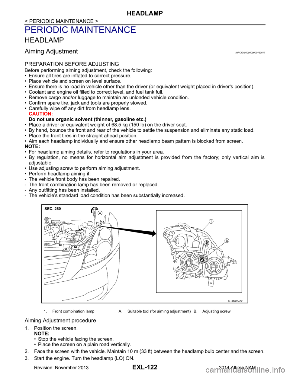
• Use adjusting screw to perform aiming adjustment.
• Perform headlamp aiming if:
- The vehicle front body has been repaired.
- The front combination lamp has been removed or replaced.
- Any outfitting has been installed.
- The vehicle’s standard load condition has been substantially increased.
Aiming Adjustment procedure
1. Position the screen.
NOTE:
• Stop the vehicle facing the screen.
• Place the screen on a plain road vertically.
2. Face the screen with the vehicle. Maintain 10 m (33 ft) between the headlamp bulb center and the screen.
3. Start the engine. Turn the headlamp (LO) ON.
1. Front combination lamp A. Suitable tool (for aiming adjustment) B. Adjusting screw
ALLIA0034ZZ
Revision: November 20132014 Altima NAMRevision: November 20132014 Altima NAM
Page 2390 of 4801

EXL-124
< PERIODIC MAINTENANCE >
FRONT FOG LAMP
FRONT FOG LAMP
Aiming AdjustmentINFOID:0000000009463618
PREPARATION BEFORE ADJUSTING
The fog lamp is a semi-sealed beam type which uses a replaceable halogen bulb. Before performing aiming
adjustment procedure, check the following:
• Ensure all tires are inflated to correct pressure.
• Place vehicle and screen on level surface.
• Ensure there is no load in vehicle other than the driver (or equivalent weight placed in driver's position).
• Coolant and engine oil filled to correct level, and fuel tank full.
• Remove cargo and/or luggage to maintain an unloaded vehicle condition.
• Confirm spare tire, jack and tools are properly stowed.
• Carefully wipe off any dirt from headlamp lens. CAUTION:
Do not use organic solvent (thinner, gasoline etc.)
• Place a driver or equivalent weight of 68.5 kg (150 lb) on the driver seat.
• By hand, bounce the front and rear of the vehicle to settle the suspension and eliminate any static load.
• Place the front tires in the straight ahead position.
• Aim each headlamp individually and ensure other headlamp beam pattern is blocked from screen.
NOTE:
• For headlamp aiming details, refer to regulations in your area.
• By regulation, no means for horizontal aim adjustment is provided from the factory; only vertical aim is
adjustable.
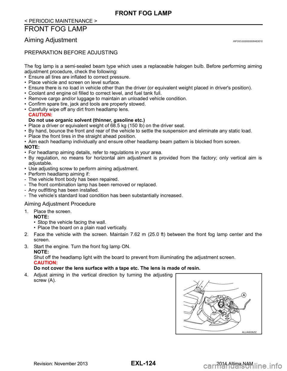
• Use adjusting screw to perform aiming adjustment.
• Perform headlamp aiming if:
- The vehicle front body has been repaired.
- The front combination lamp has been removed or replaced.
- Any outfitting has been installed.
- The vehicle’s standard load condition has been substantially increased.
Aiming Adjustment Procedure
1. Place the screen. NOTE:
• Stop the vehicle facing the wall.
• Place the board on a plain road vertically.
2. Face the vehicle with the screen. Maintain 7.62 m (25.0 ft) between the front fog lamp center and the
screen.
3. Start the engine. Turn the front fog lamp ON. NOTE:
Shut off the headlamp light with the board to prevent from illuminating the adjustment screen.
CAUTION:
Do not cover the lens surface with a tape etc. The lens is made of resin.
4. Adjust aiming in the vertical direction by turning the adjusting screw (A).
ALLIA0035ZZ
Revision: November 20132014 Altima NAMRevision: November 20132014 Altima NAM
Page 3994 of 4801

SRC-1
RESTRAINTS
C
D E
F
G
I
J
K L
M
SECTION SRC
A
B
SRC
N
O P
CONTENTS
SRS AIRBAG CONTROL SYSTEM
PRECAUTION ................ ...............................4
PRECAUTIONS .............................................. .....4
Precaution for Supplemental Restraint System
(SRS) "AIR BAG" and "SEAT BELT PRE-TEN-
SIONER" ............................................................. ......
4
Precaution for SRS "AIR BAG" and "SEAT BELT
PRE-TENSIONER" Service ................................ ......
4
SYSTEM DESCRIPTION ..............................5
COMPONENT PARTS ................................... .....5
Component Parts Location .................................. ......5
Component Description .............................................6
Driver Air Bag Module ...............................................7
Front Passenger Air Bag Module ..............................7
Front Side Air Bag Module .................................. ......7
Side Curtain Air Bag Module .....................................7
Front Seat Belt Pre-tensioner ....................................8
Air Bag Diagnosis Sensor Unit ..................................8
Crash Zone Sensor ...................................................8
Front Side Air Bag Satellite Sensor ...........................8
Rear Side Air Bag Satellite Sensor ...........................9
Front Door Satellite Sensor .......................................9
SRS Component Connectors ....................................9
SYSTEM .............................................................11
SRS AIR BAG SYSTEM ............................................11
SRS AIR BAG SYSTEM : Sy stem Diagram ............11
SRS AIR BAG SYSTEM : System Description ... ....11
OCCUPANT CLASSIFICATION SYSTEM ............ ....11
OCCUPANT CLASSIFICATION SYSTEM : Sys-
tem Diagram ........................................................ ....
12
OCCUPANT CLASSIFICATION SYSTEM : Sys-
tem Description ................................................... ....
12
SEAT BELT WARNING LAMP SYSTEM ..................13
SEAT BELT WARNING LAMP SYSTEM : System
Diagram ............................................................... ....
13
SEAT BELT WARNING LAMP SYSTEM : System
Description ........................................................... ....
14
DIAGNOSIS SYSTEM (AIR BAG) ....................15
Diagnosis Description ..............................................15
SRS Operation Check .............................................15
Trouble Diagnosis with CONSULT ..........................16
Trouble Diagnosis without CONSULT .....................17
SRS History Check ..................................................17
SRS Final Check .....................................................17
CONSULT Function (AIR BAG) ...............................17
CONSULT Function (OCCUPANT DETECTION) ....18
ECU DIAGNOSIS INFORMATION ..............19
DIAGNOSIS SENSOR UNIT .............................19
DTC Index ........................................................... ....19
Flash Code Index ....................................................23
WIRING DIAGRAM ......................................26
SRS AIR BAG SYSTEM ...................................26
Wiring Diagram .................................................... ....26
BASIC INSPECTION ...................................40
DIAGNOSIS AND REPAIR WORK FLOW .......40
Work Flow ............................................................ ....40
INSPECTION AND ADJUSTMENT ..................42
ADDITIONAL SERVICE WHEN REPLACING
CONTROL UNIT .................................................... ....
42
ADDITIONAL SERVICE WHEN REPLACING
CONTROL UNIT : Description ............................. ....
42
ADDITIONAL SERVICE WHEN REPLACING
CONTROL UNIT : Special Repair Requirement .. ....
42
ZERO POINT RESET ............................................. ....42
ZERO POINT RESET : Description .........................42
ZERO POINT RESET : Special Repair Require-
ment ..................................................................... ....
42
Revision: November 20132014 Altima NAMRevision: November 20132014 Altima NAM
Page 4154 of 4801

PRECAUTIONSSTC-3
< PRECAUTION >
C
D E
F
H I
J
K L
M A
B
STC
N
O P
PRECAUTION
PRECAUTIONS
Precaution for Supplemental Restraint System (SRS) "AIR BAG" and "SEAT BELT
PRE-TENSIONER"
INFOID:0000000009951730
The Supplemental Restraint System such as “A IR BAG” and “SEAT BELT PRE-TENSIONER”, used along
with a front seat belt, helps to reduce the risk or severi ty of injury to the driver and front passenger for certain
types of collision. Information necessary to service t he system safely is included in the SR and SB section of
this Service Manual.
WARNING:
• To avoid rendering the SRS inoper ative, which could increase the risk of personal injury or death in
the event of a collision which would result in air bag inflation, all maintenance must be performed by
an authorized NISSAN/INFINITI dealer.
• Improper maintenance, including in correct removal and installation of the SRS, can lead to personal
injury caused by unintentional act ivation of the system. For removal of Spiral Cable and Air Bag
Module, see the SR section.
• Do not use electrical test equipm ent on any circuit related to the SRS unless instructed to in this
Service Manual. SRS wiring harnesses can be identi fied by yellow and/or orange harnesses or har-
ness connectors.
PRECAUTIONS WHEN USING POWER TOOLS (AIR OR ELECTRIC) AND HAMMERS
WARNING:
• When working near the Airbag Diagnosis Sensor Un it or other Airbag System sensors with the Igni-
tion ON or engine running, DO NOT use air or el ectric power tools or strike near the sensor(s) with a
hammer. Heavy vibration could activate the sensor( s) and deploy the air bag(s), possibly causing
serious injury.
• When using air or electric power tools or hammers , always switch the Ignition OFF, disconnect the
battery and wait at least three mi nutes before performing any service.
Service Notice and Precautions for Hydrau lic Pump Electric Power Steering System
INFOID:0000000009460340
• Check each tire for proper air pressure and size. Refer to WT-60, "Tire".
• Verify that the steering system components are G enuine NISSAN parts and have been installed properly.
• Check the steering column for loose mounting bolts.
• Check the steering gear assembly for loose mounting bolts. Check the inner sockets and outer sockets for
damage or wear. Inspect the boots and seals for leakage of power steering fluid.
• Verify proper wheel alignment. Refer to FSU-7, "Inspection and Adjustment"
.
• Check for any damage, wear, or modification to the suspension and body that would result in increased
weight or an improper wheelarch height. Refer to FSU-26, "Wheelarch Height (Unladen*
1)".
• Check for proper battery voltage.
• Verify that all power steering pump assembly connections are clean and fully seated.
• Verify that only Genuine NISSAN E-PSF is used. Use of any power steering fluid other than Genuine NIS-
SAN E-PSF will prevent the power st eering system from proper operation.
• An audible high pitch noise may be heard from the engine compartment when the steering wheel is oper-
ated, particularly at low speeds such as a parking lot maneuver. This condition is not a malfunction, rather
normal system operation. Steering at low speeds or parking lot maneuvers demands higher hydraulic assis-
tance, resulting in larger power st eering pump load and increased system noise.
• The power steering pump is electrically controlled by the power steering control module.
• Before connecting or disconnecting the power steeri ng control module harness connectors, turn ignition
switch “OFF” and disconnect battery ground cable. Batter y voltage is applied to power steering control mod-
ule even if ignition switch is turned “OFF”.
Revision: November 20132014 Altima NAMRevision: November 20132014 Altima NAM