2014 NISSAN TEANA maintenance schedule
[x] Cancel search: maintenance schedulePage 1170 of 4801
![NISSAN TEANA 2014 Service Manual
EC-170
< BASIC INSPECTION >[QR25DE]
BASIC INSPECTION
BASIC INSPECTION
Work ProcedureINFOID:0000000009462129
1.INSPECTION START
1. Check service records for any recent repairs that ma y indicate a rel NISSAN TEANA 2014 Service Manual
EC-170
< BASIC INSPECTION >[QR25DE]
BASIC INSPECTION
BASIC INSPECTION
Work ProcedureINFOID:0000000009462129
1.INSPECTION START
1. Check service records for any recent repairs that ma y indicate a rel](/manual-img/5/57390/w960_57390-1169.png)
EC-170
< BASIC INSPECTION >[QR25DE]
BASIC INSPECTION
BASIC INSPECTION
Work ProcedureINFOID:0000000009462129
1.INSPECTION START
1. Check service records for any recent repairs that ma y indicate a related malfunction, or a current need for
scheduled maintenance.
2. Open engine hood and check the following:
- Harness connectors for improper connections
- Wiring harness for improper connections, pinches and cut
- Vacuum hoses for splits, kinks and improper connections
- Hoses and ducts for leaks
- Air cleaner clogging
- Gasket
3. Confirm that electrical or mechanical loads are not applied.
- Headlamp switch is OFF.
- Air conditioner switch is OFF.
- Rear window defogger switch is OFF.
- Steering wheel is in the straight-ahead position, etc.
4. Start engine and warm it up until engine coolant temperature indicator points the middle of gauge.
Ensure engine stays below 1,000 rpm.
5. Run engine at about 2,000 rpm for about 2 minutes under no load.
6. Make sure that no DTC is displayed with CONSULT or GST.
Is any DTC detected?
YES >> GO TO 2.
NO >> GO TO 3.
2.REPAIR OR REPLACE
Repair or replace components as necessary according to corresponding Diagnostic Procedure.
>> GO TO 3.
3.CHECK TARGET IDLE SPEED
1. Run engine at about 2,000 rpm for about 2 minutes under no load.
SEF983U
SEF976U
SEF977U
Revision: November 20132014 Altima NAMRevision: November 20132014 Altima NAM
Page 1675 of 4801
![NISSAN TEANA 2014 Service Manual
BASIC INSPECTIONEC-675
< BASIC INSPECTION > [VQ35DE]
C
D E
F
G H
I
J
K L
M A
EC
NP
O
BASIC INSPECTION
Work ProcedureINFOID:0000000009462550
1.INSPECTION START
1. Check service records for any recent NISSAN TEANA 2014 Service Manual
BASIC INSPECTIONEC-675
< BASIC INSPECTION > [VQ35DE]
C
D E
F
G H
I
J
K L
M A
EC
NP
O
BASIC INSPECTION
Work ProcedureINFOID:0000000009462550
1.INSPECTION START
1. Check service records for any recent](/manual-img/5/57390/w960_57390-1674.png)
BASIC INSPECTIONEC-675
< BASIC INSPECTION > [VQ35DE]
C
D E
F
G H
I
J
K L
M A
EC
NP
O
BASIC INSPECTION
Work ProcedureINFOID:0000000009462550
1.INSPECTION START
1. Check service records for any recent repairs that may indicate a related malfunction, or a current need for scheduled maintenance.
2. Open engine hood and check the following:
- Harness connectors for improper connections
- Wiring harness for improper connections, pinches and cut
- Vacuum hoses for splits, kinks and improper connections
- Hoses and ducts for leakage
- Air cleaner clogging
- Gasket
3. Check that electrical or mechanical loads are not applied.
- Head lamp switch is OFF.
- Air conditioner switch is OFF.
- Rear window defogger switch is OFF.
- Steering wheel is in the straight-ahead position, etc.
4. Start engine and warm it up until engine coolant temperature indicator points to the middle of gauge.
Check that engine stays below 1,000 rpm.
5. Run engine at approximately 2,000 rpm for approximately 2 min- utes under no load.
6. Check that no DTC is displayed with CONSULT or GST.
Are any DTCs detected?
YES >> GO TO 2.
NO >> GO TO 3.
2.REPAIR OR REPLACE
Repair or replace components as necessary according to corresponding Diagnostic Procedure.
>> GO TO 3
3.CHECK TARGET IDLE SPEED
1. Run engine at approximately 2,000 rpm for approximately 2 minutes under no load.
SEF983U
SEF976U
SEF977U
Revision: November 20132014 Altima NAMRevision: November 20132014 Altima NAM
Page 2135 of 4801
![NISSAN TEANA 2014 Service Manual
AIR CLEANER FILTEREM-137
< PERIODIC MAINTENANCE > [VQ35DE]
C
D E
F
G H
I
J
K L
M A
EM
NP
O
AIR CLEANER FILTER
Exploded ViewINFOID:0000000009460533
Removal and InstallationINFOID:0000000009460534
REM NISSAN TEANA 2014 Service Manual
AIR CLEANER FILTEREM-137
< PERIODIC MAINTENANCE > [VQ35DE]
C
D E
F
G H
I
J
K L
M A
EM
NP
O
AIR CLEANER FILTER
Exploded ViewINFOID:0000000009460533
Removal and InstallationINFOID:0000000009460534
REM](/manual-img/5/57390/w960_57390-2134.png)
AIR CLEANER FILTEREM-137
< PERIODIC MAINTENANCE > [VQ35DE]
C
D E
F
G H
I
J
K L
M A
EM
NP
O
AIR CLEANER FILTER
Exploded ViewINFOID:0000000009460533
Removal and InstallationINFOID:0000000009460534
REMOVAL
CAUTION:
It is not necessary to remove the front ai r duct to replace the air cleaner filter.
NOTE:
Replace the air cleaner filter per the periodic maintenance schedule or as necessary. Refer to MA-7, "FOR
USA AND CANADA : Introduction of Periodic Maintenance".
1. Unhook air cleaner case side clips and lift air cleaner case (upper).
2. Remove the air cleaner filter.
INSTALLATION
Installation is in the reverse order of removal.
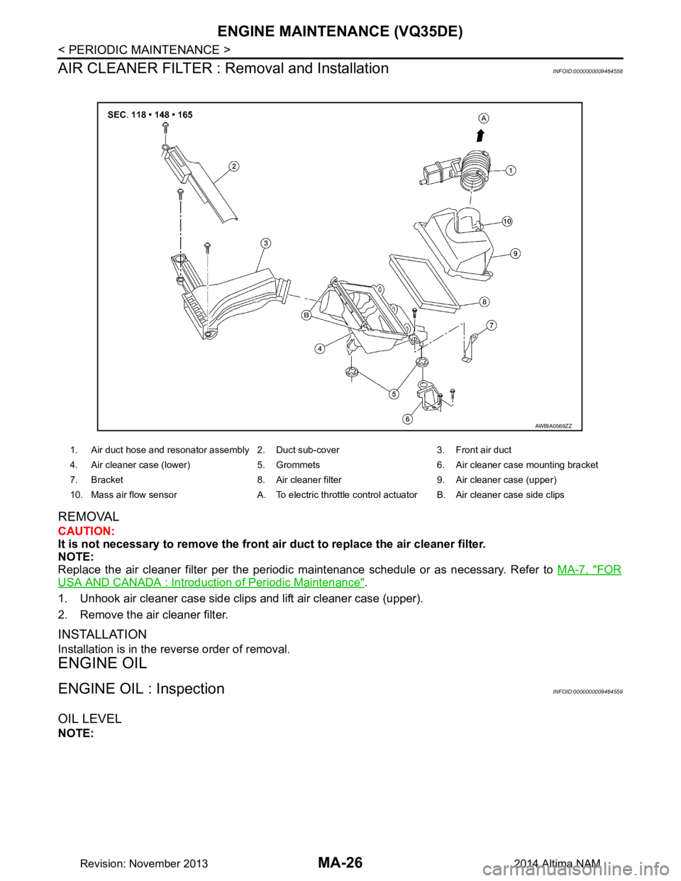
1. Air duct hose and resonator assembly 2. Duct sub-cover 3. Front air duct
4. Air cleaner case (lower) 5. Grommets 6. Air cleaner case mounting bracket
7. Bracket 8. Air cleaner filter 9. Air cleaner case (upper)
10. Mass air flow sensor A. To electric throttle control actuator B. Air cleaner case side clips
AWBIA0569ZZ
Revision: November 20132014 Altima NAM
Page 3191 of 4801

PERIODIC MAINTENANCEMA-7
< PERIODIC MAINTENANCE >
C
D E
F
G H
I
J
K L
M B
MA
N
O A
PERIODIC MAINTENANCE
FOR USA AND CANADA
FOR USA AND CANADA : Introduc
tion of Periodic MaintenanceINFOID:0000000009889991
The following tables show the normal maintenanc e schedule. Depending upon weather and atmospheric con-
ditions, varying road surfaces, indi vidual driving habits and vehicle usage, additional or more frequent mainte-
nance may be required.
Periodic maintenance beyond th e last period shown on the tables requires similar maintenance.
Emission Control System Maintenance
Abbreviations: R = Replace. I = Inspec t. Correct or replace if necessary.
MAINTENANCE OPERATION MAINTENANCE INTERVAL
Perform at number of miles, kilometers
or months, whichever comes first. Miles x 1,000
(km x 1,000) Months 5
(8) 6 10
(16) 12 15
(24) 18 20
(32) 24 25
(40) 30 30
(48) 36 35
(56) 42 40
(64) 48 45
(72) 54
Drive belt NOTE (1) I*
Air cleaner filter NOTE (2) R
EVAP vapor lines I* I*
Fuel lines I* I*
Fuel filter NOTE (3)
Engine coolant* NOTE (4)(5)
Engine oil RRRRRRRRR
Engine oil filter (Use genuine NISSAN
engine oil filter or equivalent) RRRRRRRRR
Spark plugs (Iridium - tipped type) NOTE (6) Replace every 105,000 miles (168,000 km)
Intake and exhaust valve clearance* NOTE (7)
MAINTENANCE OPERATION MAINTENANCE INTERVAL
Perform at number of miles, kilometers
or months, whichever comes first. Miles x 1,000
(km x 1,000)
Months 50
(80)
60 55
(88)
66 60
(96)
72 65
(104)
78 70
(112)
84 75
(120)
90 80
(128)
96 85
(136)
102 90
(144)
108
Drive belt NOTE (1)I*I*I*I*I*
Air cleaner filter NOTE (2) R R
EVAP vapor lines I* I*
Fuel lines I* I*
Fuel filter NOTE (3)
Engine coolant* NOTE (4)(5)
Engine oil RRRRRRRRR
Engine oil filter (Use genuine NISSAN
engine oil filter or equivalent) RRRRRRRRR
Spark plugs (Iridium - tipped type) NOTE (6) Replace every 105,000 miles (168,000 km)
Intake and exhaust valve clearance* NOTE (7)
MAINTENANCE OPERATION MAINTENANCE INTERVAL
Reference Page
Perform at number of miles, kilometers
or months, whichever comes first. Miles x 1,000
(km x 1,000)
Months 95
(152)
11 4 100
(160)
120 105
(168)
126 11 0
(176)
132 11 5
(184)
138 120
(192)
144
Drive belt NOTE (1) I* I* I* MA-13
(QR25DE)
MA-22
(VQ35DE)
Air cleaner filter NOTE (2) R MA-17
(QR25DE)
MA-26
(VQ35DE)
Revision: November 20132014 Altima NAM
Page 3210 of 4801

MA-26
< PERIODIC MAINTENANCE >
ENGINE MAINTENANCE (VQ35DE)
AIR CLEANER FILTER : Removal and Installation
INFOID:0000000009464558
REMOVAL
CAUTION:
It is not necessary to remove the front air duct to replace the air cleaner filter.
NOTE:
Replace the air cleaner filter per the periodic maintenance schedule or as necessary. Refer to MA-7, "FOR
USA AND CANADA : Introduction of Periodic Maintenance".
1. Unhook air cleaner case side clips and lift air cleaner case (upper).
2. Remove the air cleaner filter.
INSTALLATION
Installation is in the reverse order of removal.
ENGINE OIL
ENGINE OIL : InspectionINFOID:0000000009464559
OIL LEVEL
NOTE:
1. Air duct hose and resonator assembly 2. Duct sub-cover 3. Front air duct
4. Air cleaner case (lower) 5. Grommets 6. Air cleaner case mounting bracket
7. Bracket 8. Air cleaner filter 9. Air cleaner case (upper)
10. Mass air flow sensor A. To electric throttle control actuator B. Air cleaner case side clips
AWBIA0569ZZ
Revision: November 20132014 Altima NAM
Page 3224 of 4801

MA-40
< PERIODIC MAINTENANCE >
CHASSIS AND BODY MAINTENANCE
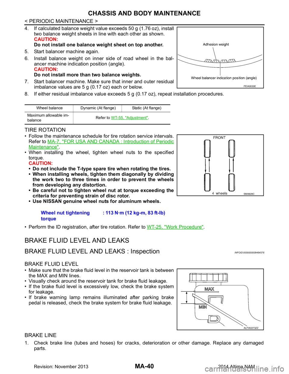
4. If calculated balance weight value exceeds 50 g (1.76 oz), installtwo balance weight sheets in line with each other as shown.
CAUTION:
Do not install one balance weight sheet on top another.
5. Start balancer machine again.
6. Install balance weight on inner side of road wheel in the bal- ancer machine indication position (angle).
CAUTION:
Do not install more than two balance weights.
7. Start balancer machine. Make sure that inner and outer residual imbalance values are 5 g (0.17 oz) each or below.
8. If either residual imbalance value exceeds 5 g (0.17 oz), repeat installation procedures.
TIRE ROTATION
• Follow the maintenance schedule for tire rotation service intervals.
Refer to MA-7, "FOR USA AND CANADA : Introduction of Periodic
Maintenance".
• When installing the wheel, tighten wheel nuts to the specified torque.
CAUTION:
• Do not include the T-type spare tire when rotating the tires.
• When installing wheels, tighten them diagonally by dividing
the work two to three times in order to prevent the wheels
from developing any distortion.
• Be careful not to tighten wheel nut at torque exceeding the criteria for preventing strain of disc rotor.
• Use NISSAN genuine wheel nuts for aluminum wheels.
• Perform the ID registration, after tire rotation. Refer to WT-25, "Work Procedure"
.
BRAKE FLUID LEVEL AND LEAKS
BRAKE FLUID LEVEL AND LEAKS : InspectionINFOID:0000000009464576
BRAKE FLUID LEVEL
• Make sure that the brake fluid level in the reservoir tank is between
the MAX and MIN lines.
• Visually check around the reservoir tank for brake fluid leakage.
• If the brake fluid level is excessively low, check the brake system for leakage.
• If brake warning lamp remains illuminated after parking brake
pedal is released, check the brake system for brake fluid leakage.
BRAKE LINE
1. Check brake line (tubes and hoses) for cracks, deterioration or other damage. Replace any damaged
parts.
Wheel balance Dynamic (At flange) Static (At flange)
Maximum allowable im-
balance Refer to
WT-55, "Adjustment"
.
PEIA0033E
Wheel nut tightening
torque : 113 N·m (12 kg-m, 83 ft-lb)
SMA829C
ALFIA0273ZZ
Revision: November 20132014 Altima NAM
Page 3723 of 4801

RSU-6
< PERIODIC MAINTENANCE >
REAR SUSPENSION ASSEMBLY
• Check the wheelarch height in the unladen condition. Refer to RSU-17, "Wheelarch Height (Unladen*1)".
GENERAL INFORMATION AND RECOMMENDATIONS
1. A Four-Wheel Thrust Alignment should be performed.
• This type of alignment is recommended for any NISSAN vehicle.
• The four-wheel “thrust” process helps ensure that the vehicle is properly aligned and the steering wheel
is centered.
• The alignment machine itself should be ca pable of accepting any NISSAN vehicle.
• The alignment machine should be checked to ensure that it is level.
2. Make sure the alignment machine is properly calibrated. • Your alignment machine should be regularly calibrated in order to give correct information.
• Check with the manufacturer of your specific al ignment machine for their recommended Service/Cali-
bration Schedule.
THE ALIGNMENT PROCESS
IMPORTANT: Use only the alignment specifications listed in this Service Manual. Refer to RSU-17,
"Wheelarch Height (Unladen*1)".
1. When displaying the alignment settings, many alignm ent machines use “indicators”: (Green/red, plus or
minus, Go/No Go). Do NOT use these indicators.
• The alignment specifications programmed into your alignment machine that operate these indicators
may not be correct.
• This may result in an ERROR.
2. Most camera-type alignment machines are equipped with both "Rolling Compensation" method and optional "Jacking Compensation" method to "com pensate" the alignment targets or head units.
"Rolling Compensation" is the preferred method.
• If using the "Rolling Compensation" method, after installing the alignment targets or head units, push or pull on the rear wheel to move the vehicle. Do not push or pull the vehicle body.
• If using the "Jacking Compensation" method, after in stalling the alignment targets or head units, raise
the vehicle and rotate the wheels 1/2 turn both ways.
NOTE:
Do not use the "Rolling Compensation" method if you are using sensor-type alignment equipment.
• Follow all instructions for the alignment machine you are using for more information.
CAMBER and TOE
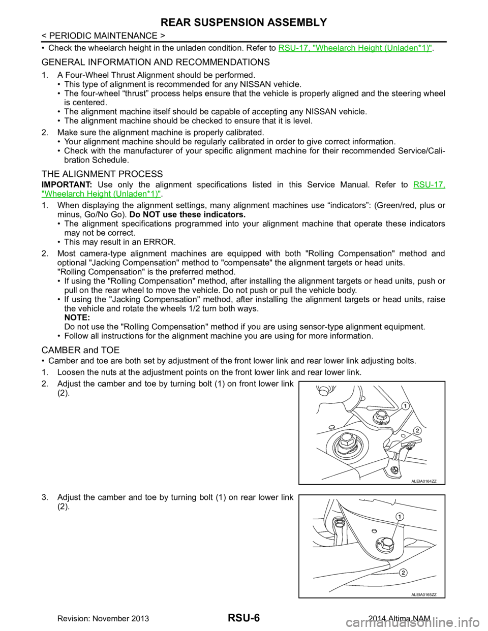
• Camber and toe are both set by adjustment of the fr ont lower link and rear lower link adjusting bolts.
1. Loosen the nuts at the adjustment points on the front lower link and rear lower link.
2. Adjust the camber and toe by turning bolt (1) on front lower link (2).
3. Adjust the camber and toe by turning bolt (1) on rear lower link (2).
ALEIA0164ZZ
ALEIA0165ZZ
Revision: November 20132014 Altima NAM
Page 4731 of 4801

WT-56
< REMOVAL AND INSTALLATION >
ROAD WHEEL TIRE ASSEMBLY
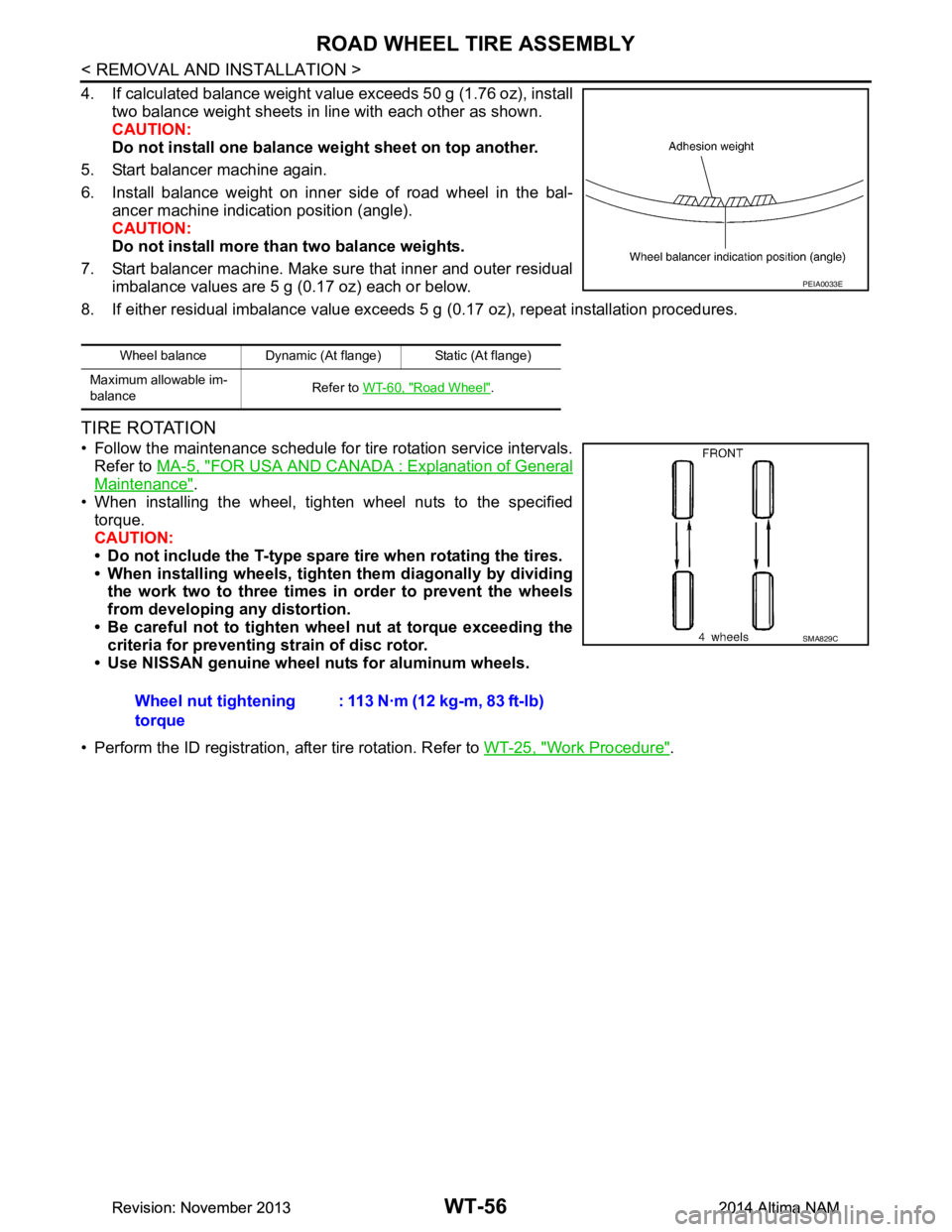
4. If calculated balance weight value exceeds 50 g (1.76 oz), installtwo balance weight sheets in line with each other as shown.
CAUTION:
Do not install one balance weight sheet on top another.
5. Start balancer machine again.
6. Install balance weight on inner side of road wheel in the bal- ancer machine indication position (angle).
CAUTION:
Do not install more than two balance weights.
7. Start balancer machine. Make sure that inner and outer residual imbalance values are 5 g (0.17 oz) each or below.
8. If either residual imbalance value exceeds 5 g (0.17 oz), repeat installation procedures.
TIRE ROTATION
• Follow the maintenance schedule for tire rotation service intervals.
Refer to MA-5, "FOR USA AND CANADA : Explanation of General
Maintenance".
• When installing the wheel, tighten wheel nuts to the specified torque.
CAUTION:
• Do not include the T-type spare tire when rotating the tires.
• When installing wheels, tighten them diagonally by dividing
the work two to three times in order to prevent the wheels
from developing any distortion.
• Be careful not to tighten wheel nut at torque exceeding the criteria for preventing strain of disc rotor.
• Use NISSAN genuine wheel nuts for aluminum wheels.
• Perform the ID registration, after tire rotation. Refer to WT-25, "Work Procedure"
.
Wheel balance Dynamic (At flange) Static (At flange)
Maximum allowable im-
balance Refer to
WT-60, "Road Wheel"
.
PEIA0033E
Wheel nut tightening
torque : 113 N·m (12 kg-m, 83 ft-lb)
SMA829C
Revision: November 20132014 Altima NAMRevision: November 20132014 Altima NAM