Page 2328 of 4801
EXL-62
< WIRING DIAGRAM >
TURN SIGNAL AND HAZARD WARNING LAMPS
ABLIA5206GB
Revision: November 20132014 Altima NAMRevision: November 20132014 Altima NAM
Page 2329 of 4801
TURN SIGNAL AND HAZARD WARNING LAMPSEXL-63
< WIRING DIAGRAM >
C
D E
F
G H
I
J
K
M A
B
EXL
N
O P
ABLIA4743GB
Revision: November 20132014 Altima NAMRevision: November 20132014 Altima NAM
Page 2330 of 4801
EXL-64
< WIRING DIAGRAM >
TURN SIGNAL AND HAZARD WARNING LAMPS
ABLIA5165GB
Revision: November 20132014 Altima NAMRevision: November 20132014 Altima NAM
Page 2331 of 4801
TURN SIGNAL AND HAZARD WARNING LAMPSEXL-65
< WIRING DIAGRAM >
C
D E
F
G H
I
J
K
M A
B
EXL
N
O P
ABLIA5166GB
Revision: November 20132014 Altima NAMRevision: November 20132014 Altima NAM
Page 2332 of 4801
EXL-66
< WIRING DIAGRAM >
TURN SIGNAL AND HAZARD WARNING LAMPS
ABLIA5167GB
Revision: November 20132014 Altima NAMRevision: November 20132014 Altima NAM
Page 2333 of 4801
TURN SIGNAL AND HAZARD WARNING LAMPSEXL-67
< WIRING DIAGRAM >
C
D E
F
G H
I
J
K
M A
B
EXL
N
O P
ABLIA5207GB
Revision: November 20132014 Altima NAMRevision: November 20132014 Altima NAM
Page 2372 of 4801

EXL-106
< DTC/CIRCUIT DIAGNOSIS >
TURN SIGNAL LAMP CIRCUIT
TURN SIGNAL LAMP CIRCUIT
DescriptionINFOID:0000000009463597
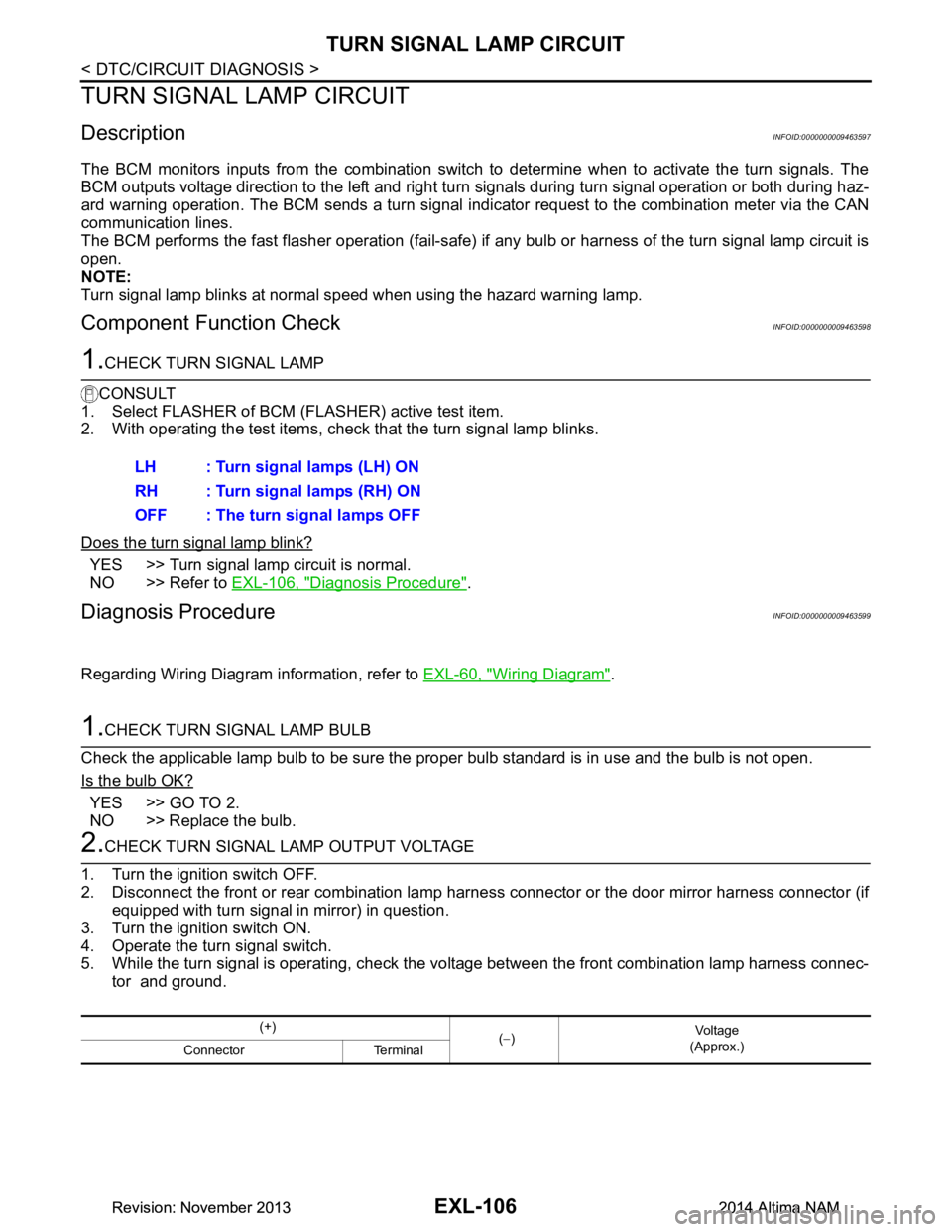
The BCM monitors inputs from the combination switch to determine when to activate the turn signals. The
BCM outputs voltage direction to the left and right turn signals during turn signal operation or both during haz-
ard warning operation. The BCM sends a turn signal indicator request to the combination meter via the CAN
communication lines.
The BCM performs the fast flasher operation (fail-safe) if any bulb or harness of the turn signal lamp circuit is
open.
NOTE:
Turn signal lamp blinks at normal speed when using the hazard warning lamp.
Component Function CheckINFOID:0000000009463598
1.CHECK TURN SIGNAL LAMP
CONSULT
1. Select FLASHER of BCM (FLASHER) active test item.
2. With operating the test items, check that the turn signal lamp blinks.
Does the turn signal lamp blink?
YES >> Turn signal lamp circuit is normal.
NO >> Refer to EXL-106, "Diagnosis Procedure"
.
Diagnosis ProcedureINFOID:0000000009463599
Regarding Wiring Diagram information, refer to EXL-60, "Wiring Diagram".
1.CHECK TURN SIGNAL LAMP BULB
Check the applicable lamp bulb to be sure the proper bulb standard is in use and the bulb is not open.
Is the bulb OK?
YES >> GO TO 2.
NO >> Replace the bulb.
2.CHECK TURN SIGNAL LAMP OUTPUT VOLTAGE
1. Turn the ignition switch OFF.
2. Disconnect the front or rear combination lamp har ness connector or the door mirror harness connector (if
equipped with turn signal in mirror) in question.
3. Turn the ignition switch ON.
4. Operate the turn signal switch.
5. While the turn signal is operating, check the vo ltage between the front combination lamp harness connec-
tor and ground. LH : Turn signal lamps (LH) ON
RH : Turn signal lamps (RH) ON
OFF : The turn signal lamps OFF
(+) (− ) Vo l ta g e
(Approx.)
Connector Terminal
Revision: November 20132014 Altima NAMRevision: November 20132014 Altima NAM
Page 2381 of 4801

EXTERIOR LIGHTING SYSTEM SYMPTOMSEXL-115
< SYMPTOM DIAGNOSIS >
C
D E
F
G H
I
J
K
M A
B
EXL
N
O P
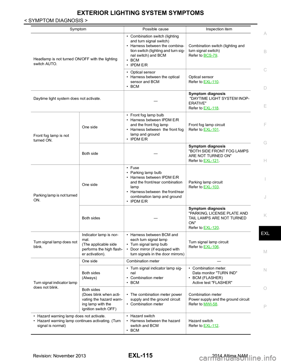
Headlamp is not turned ON/OFF with the lighting
switch AUTO. • Combination switch (lighting
and turn signal switch)
• Harness between the combina- tion switch (lighting and turn sig-
nal switch) and BCM
•BCM
• IPDM E/R Combination switch (lighting and
turn signal switch)
Refer to BCS-79.
• Optical sensor
• Harness between the optical
sensor and BCM
•BCM Optical sensor
Refer to EXL-110
.
Daytime light system does not activate. —Symptom diagnosis
"DAYTIME LIGHT SYSTEM INOP-
ERATIVE"
Refer to EXL-118
.
Front fog lamp is not
turned ON. One side
• Front fog lamp bulb
• Harness between IPDM E/R
and the front fog lamp
• Harness between the front fog lamp and ground
• IPDM E/R Front fog lamp circuit
Refer to EXL-101
.
Both side — Symptom diagnosis
"BOTH SIDE FRONT FOG LAMPS
ARE NOT TURNED ON"
Refer to EXL-121
.
Parking lamp is not turned
ON. One side•Fuse
• Parking lamp bulb
• Harness between IPDM E/R
and the front/rear combination
lamp
• Harness between the front/rear
combination lamp and ground
• IPDM E/R Parking lamp circuit
Refer to EXL-103
.
Both sides — Symptom diagnosis
"PARKING, LICENSE PLATE AND
TAIL LAMPS ARE NOT TURNED
ON"
Refer to EXL-120
.
Turn signal lamp does not
blink. Indicator lamp is nor-
mal.
(The applicable side
performs the high flash-
er activation). • Harness between BCM and
each turn signal lamp
• Turn signal lamp bulb
• Door mirror (if equipped with
turn signals in the door mirrors) Turn signal lamp circuit
Refer to EXL-106
.
Turn signal indicator lamp
does not blink. One side Combination meter —
Both sides
(Always) • Turn signal indicator lamp sig-
nal
• Combination meter
•BCM • Combination meter.
Data monitor "TURN IND"
• BCM (FLASHER) Active test "FLASHER"
Both sides
(Does blink when acti-
vating the hazard warn-
ing lamp with the
ignition switch OFF) • The combination meter power
supply and the ground circuit
• Combination meter Combination meter
Power supply and the ground circuit
Refer to MWI-58
.
• Hazard warning lamp does not activate.
• Hazard warning lamp continues activating. (Turn signal is normal) • Hazard switch
• Harness between the hazard switch and BCM
•BCM Hazard switch
Refer to EXL-112
.
Symptom Possible cause Inspection item
Revision: November 20132014 Altima NAMRevision: November 20132014 Altima NAM