2014 NISSAN TEANA warning
[x] Cancel search: warningPage 4725 of 4801

WT-50
< SYMPTOM DIAGNOSIS >
LOW TIRE PRESSURE WARNING LAMP STAYS ON
LOW TIRE PRESSURE WARNING LAMP STAYS ON
Low Tire Pressure Warning Lamp Stays On When Ignition Switch Is Turned On
INFOID:0000000009464516
1.CHECK BCM CONNECTORS
1. Turn ignition switch OFF.
2. Disconnect BCM connectors.
3. Check terminals for damage or loose connections.
Is the inspection result normal?
YES >> GO TO 2
NO >> Repair or replace damaged connectors.
2.BCM POWER SUPPLY AND GROUND CIRCUITS
Check BCM power supply and ground circuits. Refer to BCS-74, "Diagnosis Procedure"
.
Is the inspection result normal?
YES >> Replace BCM. Refer to BCS-80, "Removal and Installation".
NO >> Repair BCM circuits.
Revision: November 20132014 Altima NAMRevision: November 20132014 Altima NAM
Page 4726 of 4801

EASY FILL TIRE ALERT DOES NOT ACTIVATEWT-51
< SYMPTOM DIAGNOSIS >
C
D
F
G H
I
J
K L
M A
B
WT
N
O P
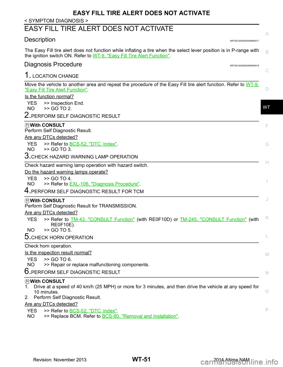
EASY FILL TIRE ALERT DOES NOT ACTIVATE
DescriptionINFOID:0000000009464517
The Easy Fill tire alert does not function while inflating a tire when the select lever position is in P-range with
the ignition switch ON. Refer to WT-9, "Easy Fill Tire Alert Function"
.
Diagnosis ProcedureINFOID:0000000009464518
1. LOCATION CHANGE
Move the vehicle to another area and repeat the procedure of the Easy Fill tire alert function. Refer to WT-9,
"Easy Fill Tire Alert Function".
Is the function normal?
YES >> Inspection End.
NO >> GO TO 2.
2.PERFORM SELF DIAGNOSTIC RESULT
With CONSULT
Perform Self Diagnostic Result.
Are any DTCs detected?
YES >> Refer to BCS-52, "DTC Index".
NO >> GO TO 3.
3.CHECK HAZARD WARNING LAMP OPERATION
Check hazard warning lamp operation with hazard switch.
Do the hazard warning lamps operate?
YES >> GO TO 4.
NO >> Refer to EXL-106, "Diagnosis Procedure"
.
4.PERFORM SELF DIAGNOSTIC RESULT FOR TCM
With CONSULT
Perform Self Diagnostic Result for TRANSMISSION.
Are any DTCs detected?
YES >> Refer to TM-43, "CONSULT Function" (with RE0F10D) or TM-245, "CONSULT Function" (with
RE0F10E).
NO >> GO TO 5.
5.CHECK HORN OPERATION
Check horn operation.
Is the inspection result normal?
YES >> GO TO 6.
NO >> Repair or replace malfunctioning components.
6.PERFORM SELF DIAGNOSTIC RESULT
With CONSULT
1. Drive at a speed of 40 km/h (25 MPH) or more fo r 3 minutes, and then drive the vehicle at any speed for
10 minutes.
2. Perform Self Diagnostic Result.
Are any DTCs detected?
YES >> Refer to BCS-52, "DTC Index".
NO >> Replace BCM. Refer to BCS-80, "Removal and Installation"
.
Revision: November 20132014 Altima NAMRevision: November 20132014 Altima NAM
Page 4738 of 4801

PRECAUTIONSWW-3
< PRECAUTION >
C
D E
F
G H
I
J
K
M A
B
WW
N
O P
PRECAUTION
PRECAUTIONS
Precaution for Supplemental Restraint System (SRS) "AIR BAG" and "SEAT BELT
PRE-TENSIONER"
INFOID:0000000009951588
The Supplemental Restraint System such as “A IR BAG” and “SEAT BELT PRE-TENSIONER”, used along
with a front seat belt, helps to reduce the risk or severi ty of injury to the driver and front passenger for certain
types of collision. Information necessary to service t he system safely is included in the SR and SB section of
this Service Manual.
WARNING:
• To avoid rendering the SRS inoper ative, which could increase the risk of personal injury or death in
the event of a collision which would result in air bag inflation, all maintenance must be performed by
an authorized NISSAN/INFINITI dealer.
• Improper maintenance, including in correct removal and installation of the SRS, can lead to personal
injury caused by unintentional act ivation of the system. For removal of Spiral Cable and Air Bag
Module, see the SR section.
• Do not use electrical test equipm ent on any circuit related to the SRS unless instructed to in this
Service Manual. SRS wiring harnesses can be identi fied by yellow and/or orange harnesses or har-
ness connectors.
PRECAUTIONS WHEN USING POWER TOOLS (AIR OR ELECTRIC) AND HAMMERS
WARNING:
• When working near the Airbag Diagnosis Sensor Un it or other Airbag System sensors with the Igni-
tion ON or engine running, DO NOT use air or el ectric power tools or strike near the sensor(s) with a
hammer. Heavy vibration could activate the sensor( s) and deploy the air bag(s), possibly causing
serious injury.
• When using air or electric power tools or hammers , always switch the Ignition OFF, disconnect the
battery and wait at least three mi nutes before performing any service.
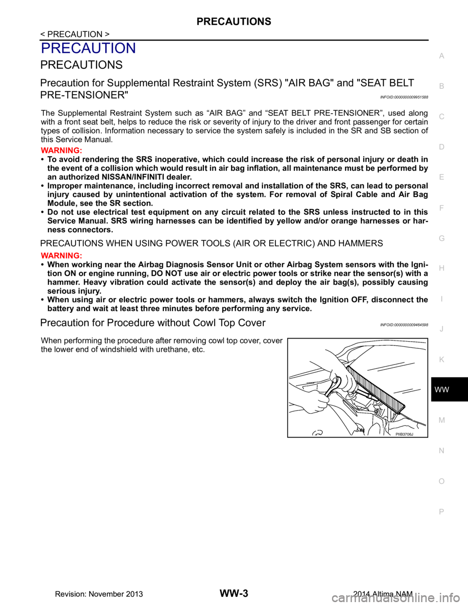
Precaution for Procedure without Cowl Top CoverINFOID:0000000009464598
When performing the procedure after removing cowl top cover, cover
the lower end of windshield with urethane, etc.
PIIB3706J
Revision: November 20132014 Altima NAMRevision: November 20132014 Altima NAM
Page 4745 of 4801

WW-10
< SYSTEM DESCRIPTION >
DIAGNOSIS SYSTEM (BCM)
DIAGNOSIS SYSTEM (BCM)
COMMON ITEM
COMMON ITEM : CONSULT Function (BCM - COMMON ITEM)INFOID:0000000009944151
CAUTION:
After disconnecting the CONSULT vehicle interface (VI) from the data link connector, the ignition must
be cycled OFF → ON (for at least 5 seconds) → OFF. If this step is not performed, the BCM may not go
to ”sleep mode”, potentially causing a di scharged battery and a no-start condition.
APPLICATION ITEM
CONSULT performs the following functions via CAN communication with BCM.
SYSTEM APPLICATION
BCM can perform the following functions.
Direct Diagnostic Mode Description
Ecu Identification The BCM part number is displayed.
Self Diagnostic Result The BCM self diagnostic results are displayed.
Data Monitor The BCM input/output data is displayed in real time.
Active Test The BCM activates outputs to test components.
Work support The settings for BCM functions can be changed.
Configuration • The vehicle specification can be read and saved.
• The vehicle specification can be written when replacing BCM.
CAN Diag Support Mntr The result of transmit/receive diagnosis of CAN communication is displayed.
System Sub System Direct Diagnostic Mode
Ecu Identification
Self Diagnostic Result
Data Monitor
Active Test
Work support
Configuration
CAN Diag Su pport Mntr
Door lock DOOR LOCK ××××
Rear window defogger REAR DEFOGGER ×××
Warning chime BUZZER ××
Interior room lamp timer INT LAMP ×××
Remote keyless entry system MULTI REMOTE ENT ×××
Exterior lamp HEADLAMP ×××
Wiper and washer WIPER ×××
Turn signal and hazard warning lamps FLASHER ××
Air conditioner AIR CONDITIONER ×
Intelligent Key system INTELLIGENT KEY ××××
Combination switch COMB SW ×
BCM BCM × × ×××
Immobilizer IMMU ×××
Interior room lamp battery saver BATTERY SAVER ××
Trunk open TRUNK ×
Vehicle security system THEFT ALM ×××
Revision: November 20132014 Altima NAMRevision: November 20132014 Altima NAM
Page 4749 of 4801

WW-14
< SYSTEM DESCRIPTION >
DIAGNOSIS SYSTEM (IPDM E/R)
APPLICATION ITEM
CONSULT performs the following functions via CAN communication with IPDM E/R.
ECU IDENTIFICATION
The IPDM E/R part number is displayed.
SELF DIAGNOSTIC RESULT
Refer to PCS-20, "DTC Index".
DATA MONITOR
Direct Diagnostic Mode Description
Ecu Identification The IPDM E/R part number is displayed.
Self Diagnostic Result The IPDM E/R self diagnostic results are displayed.
Data Monitor The IPDM E/R input/output data is displayed in real time.
Active Test The IPDM E/R activates outputs to test components.
CAN Diag Support Mntr The result of transmit/receive diagnosis of CAN communication is displayed.
Monitor Item [Unit] Main
Signals Description
MOTOR FAN REQ [%] ×Indicates cooling fan speed signal received from ECM on CAN communication
line
AC COMP REQ [On/Off] ×Indicates A/C compressor request signal received from ECM on CAN commu-
nication line
TAIL&CLR REQ [On/Off] ×Indicates position light request signal received from BCM on CAN communica-
tion line
HL LO REQ [On/Off] ×Indicates low beam request signal received from BCM on CAN communication
line
HL HI REQ [On/Off] ×Indicates high beam request signal received from BCM on CAN communication
line
FR FOG REQ [On/Off] ×Indicates front fog light request signal received from BCM on CAN communica-
tion line
FR WIP REQ [Stop/1LOW/Low/Hi] ×Indicates front wiper request signal received from BCM on CAN communication
line
WIP AUTO STOP [STOP P/ACT P] ×Indicates condition of front wiper auto stop signal
WIP PROT [Off/BLOCK] ×Indicates condition of front wiper fail-safe operation
IGN RLY1 -REQ [On/Off] Indicates ignition switch ON signal received from BCM on CAN communication
line
IGN RLY [On/Off] ×Indicates condition of ignition relay
PUSH SW [On/Off] Indicates condition of push-button ignition switch
INTER/NP SW [On/Off] Indicates condition of CVT shift position
ST RLY CONT [On/Off] Indicates starter relay status signal received from BCM on CAN communication
line
IHBT RLY -REQ [On/Off] Indicates starter control relay signal received from BCM on CAN communication
line
ST/INHI RLY [Off/ ST /INHI] Indicates condition of starter relay and starter control relay
DETENT SW [On/Off] Indicates condition of CVT shift selector (park position switch)
DTRL REQ [Off] Indicates daytime light request signal received from BCM on CAN communica-
tion line
HOOD SW [On/Off] Indicates condition of hood switch
THFT HRN REQ [On/Off] Indicates theft warning horn request signal received from BCM on CAN commu-
nication line
Revision: November 20132014 Altima NAMRevision: November 20132014 Altima NAM