2014 NISSAN TEANA warning
[x] Cancel search: warningPage 2409 of 4801
FRONT COMBINATION LAMPEXL-143
< UNIT DISASSEMBLY AND ASSEMBLY >
C
D E
F
G H
I
J
K
M A
B
EXL
N
O P
5. Rotate the halogen lamp bulb (high beam) counterclockwise and remove.
6. Rotate the side marker bulb socket counterclockwise and remove.
7. Remove the side marker lamp bulb from the sidemarker bulb socket.
Assembly
Assembly is in the reverse order of disassembly.
CAUTION:
• After installing the xenon bulb, be sure to install plastic cover securely to ensure watertightness.
• After installing, be sure to install the bulb sockets securely to ensure watertightness.
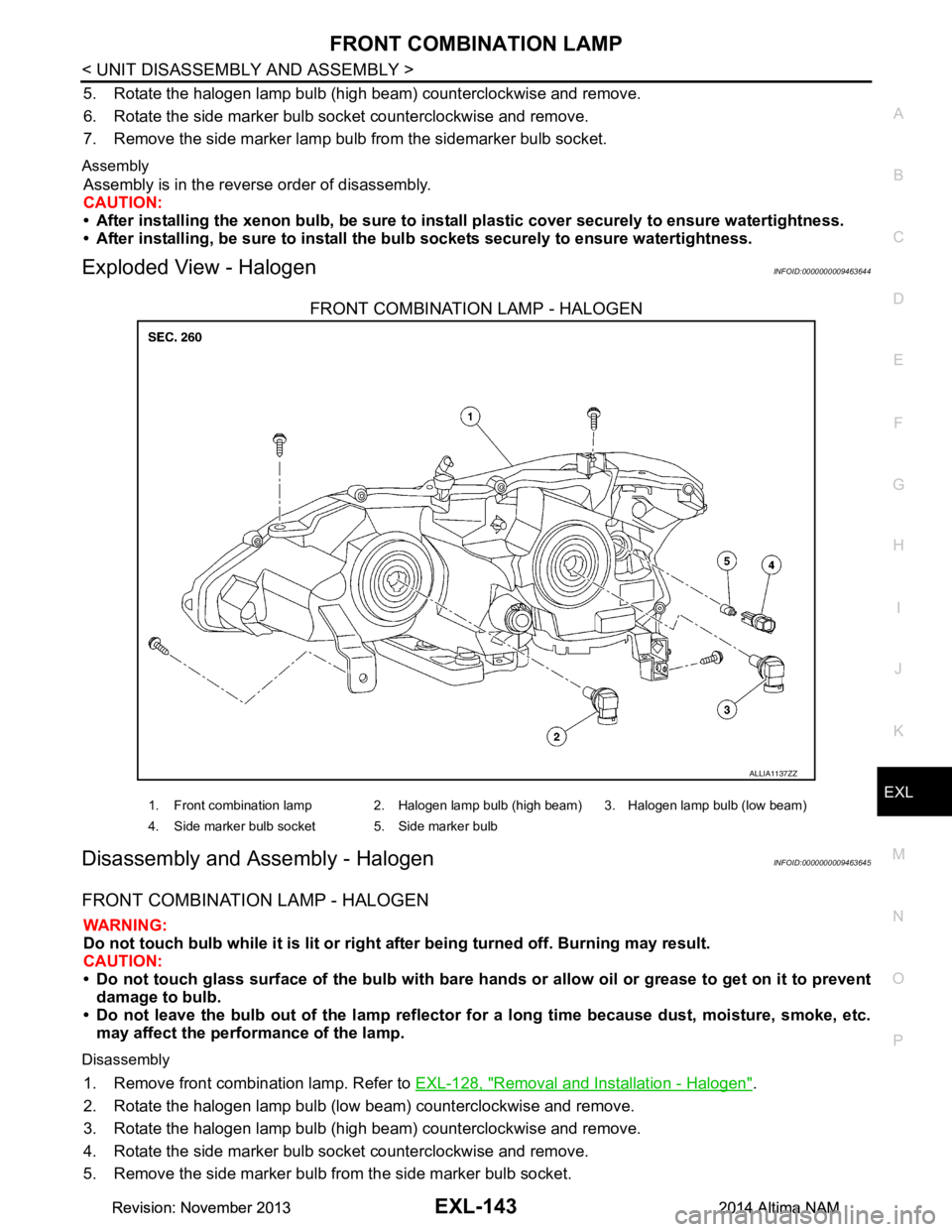
Exploded View - HalogenINFOID:0000000009463644
FRONT COMBINATION LAMP - HALOGEN
Disassembly and Assembly - HalogenINFOID:0000000009463645
FRONT COMBINATION LAMP - HALOGEN
WARNING:
Do not touch bulb while it is lit or right after being turned off. Burning may result.
CAUTION:
• Do not touch glass surface of the bulb with bare hand s or allow oil or grease to get on it to prevent
damage to bulb.
• Do not leave the bulb out of the lamp reflector fo r a long time because dust, moisture, smoke, etc.
may affect the performance of the lamp.
Disassembly
1. Remove front combination lamp. Refer to EXL-128, "Removal and Installation - Halogen".
2. Rotate the halogen lamp bulb (low beam) counterclockwise and remove.
3. Rotate the halogen lamp bulb (high beam) counterclockwise and remove.
4. Rotate the side marker bulb socket counterclockwise and remove.
5. Remove the side marker bulb from the side marker bulb socket.
ALLIA1137ZZ
1. Front combination lamp 2. Halogen lamp bulb (high beam) 3. Halogen lamp bulb (low beam)
4. Side marker bulb socket 5. Side marker bulb
Revision: November 20132014 Altima NAMRevision: November 20132014 Altima NAM
Page 2411 of 4801
REAR COMBINATION LAMPEXL-145
< UNIT DISASSEMBLY AND ASSEMBLY >
C
D E
F
G H
I
J
K
M A
B
EXL
N
O P
REAR COMBINATION LAMP
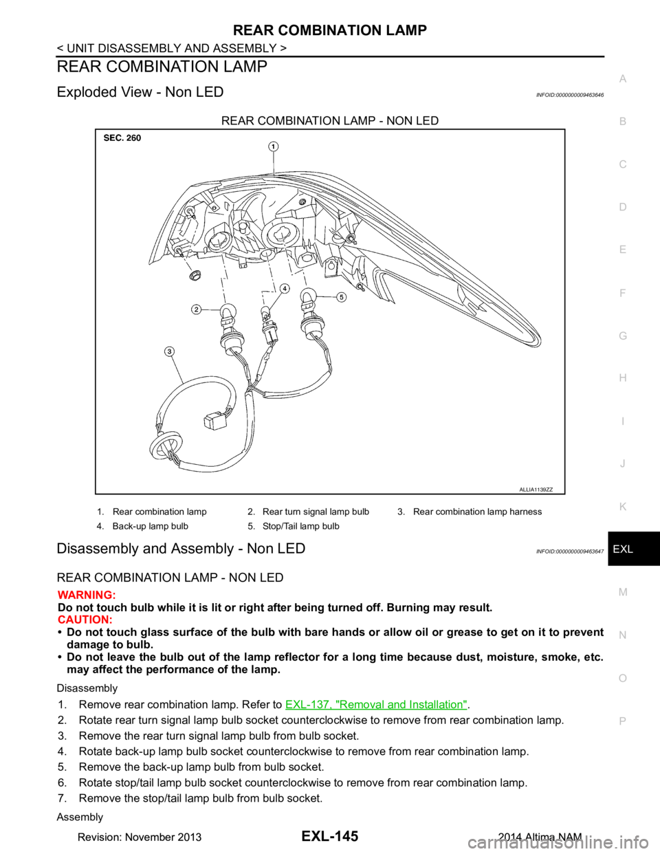
Exploded View - Non LEDINFOID:0000000009463646
REAR COMBINATION LAMP - NON LED
Disassembly and Assembly - Non LEDINFOID:0000000009463647
REAR COMBINATION LAMP - NON LED
WARNING:
Do not touch bulb while it is lit or right after being turned off. Burning may result.
CAUTION:
• Do not touch glass surface of the bulb with bare hand s or allow oil or grease to get on it to prevent
damage to bulb.
• Do not leave the bulb out of the lamp reflector fo r a long time because dust, moisture, smoke, etc.
may affect the performance of the lamp.
Disassembly
1. Remove rear combination lamp. Refer to EXL-137, "Removal and Installation".
2. Rotate rear turn signal lamp bulb socket counterclockwise to remove from rear combination lamp.
3. Remove the rear turn signal lamp bulb from bulb socket.
4. Rotate back-up lamp bulb socket counterclockwise to remove from rear combination lamp.
5. Remove the back-up lamp bulb from bulb socket.
6. Rotate stop/tail lamp bulb socket counterclockwise to remove from rear combination lamp.
7. Remove the stop/tail lamp bulb from bulb socket.
Assembly
ALLIA1139ZZ
1. Rear combination lamp 2. Rear turn signal lamp bulb 3. Rear combination lamp harness
4. Back-up lamp bulb 5. Stop/Tail lamp bulb
Revision: November 20132014 Altima NAMRevision: November 20132014 Altima NAM
Page 2412 of 4801
EXL-146
< UNIT DISASSEMBLY AND ASSEMBLY >
REAR COMBINATION LAMP
Assembly is in the reverse order of disassembly.
CAUTION:
After installing, be sure to install the bu lb sockets securely to ensure watertightness.
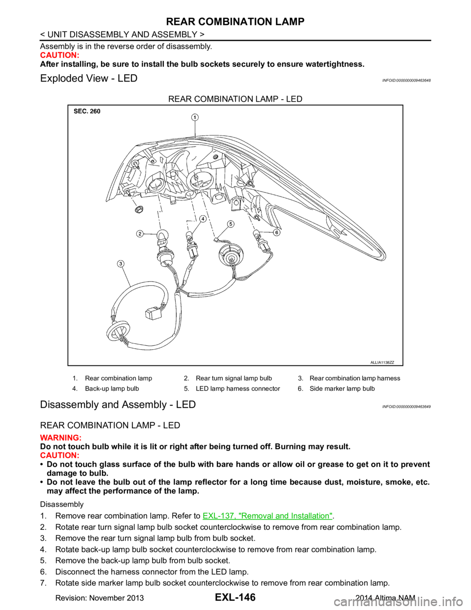
Exploded View - LED INFOID:0000000009463648
REAR COMBINATION LAMP - LED
Disassembly and Assembly - LEDINFOID:0000000009463649
REAR COMBINATION LAMP - LED
WARNING:
Do not touch bulb while it is lit or right after being turned off. Burning may result.
CAUTION:
• Do not touch glass surface of the bulb with bare hands or allow oil or grease to get on it to prevent
damage to bulb.
• Do not leave the bulb out of the lamp reflector fo r a long time because dust, moisture, smoke, etc.
may affect the performance of the lamp.
Disassembly
1. Remove rear combination lamp. Refer to EXL-137, "Removal and Installation".
2. Rotate rear turn signal lamp bulb socket counterclockwise to remove from rear combination lamp.
3. Remove the rear turn signal lamp bulb from bulb socket.
4. Rotate back-up lamp bulb socket counterclockwise to remove from rear combination lamp.
5. Remove the back-up lamp bulb from bulb socket.
6. Disconnect the harness connec tor from the LED lamp.
7. Rotate side marker lamp bulb socket counterclockwise to remove from rear combination lamp.
ALLIA1138ZZ
1. Rear combination lamp 2. Rear turn signal lamp bulb 3. Rear combination lamp harness
4. Back-up lamp bulb 5. LED lamp harness connector 6. Side marker lamp bulb
Revision: November 20132014 Altima NAMRevision: November 20132014 Altima NAM
Page 2417 of 4801
PRECAUTIONSEXT-3
< PRECAUTION >
C
D E
F
G H
I
J
L
M A
B
EXT
N
O P
PRECAUTION
PRECAUTIONS
Precaution for Supplemental Restraint System (SRS) "AIR BAG" and "SEAT BELT
PRE-TENSIONER"
INFOID:0000000009951571
The Supplemental Restraint System such as “A IR BAG” and “SEAT BELT PRE-TENSIONER”, used along
with a front seat belt, helps to reduce the risk or severi ty of injury to the driver and front passenger for certain
types of collision. Information necessary to service t he system safely is included in the SR and SB section of
this Service Manual.
WARNING:
• To avoid rendering the SRS inoper ative, which could increase the risk of personal injury or death in
the event of a collision which would result in air bag inflation, all maintenance must be performed by
an authorized NISSAN/INFINITI dealer.
• Improper maintenance, including in correct removal and installation of the SRS, can lead to personal
injury caused by unintentional act ivation of the system. For removal of Spiral Cable and Air Bag
Module, see the SR section.
• Do not use electrical test equipm ent on any circuit related to the SRS unless instructed to in this
Service Manual. SRS wiring harnesses can be identi fied by yellow and/or orange harnesses or har-
ness connectors.
PRECAUTIONS WHEN USING POWER TOOLS (AIR OR ELECTRIC) AND HAMMERS
WARNING:
• When working near the Airbag Diagnosis Sensor Un it or other Airbag System sensors with the Igni-
tion ON or engine running, DO NOT use air or el ectric power tools or strike near the sensor(s) with a
hammer. Heavy vibration could activate the sensor( s) and deploy the air bag(s), possibly causing
serious injury.
• When using air or electric power tools or hammers , always switch the Ignition OFF, disconnect the
battery and wait at least three mi nutes before performing any service.
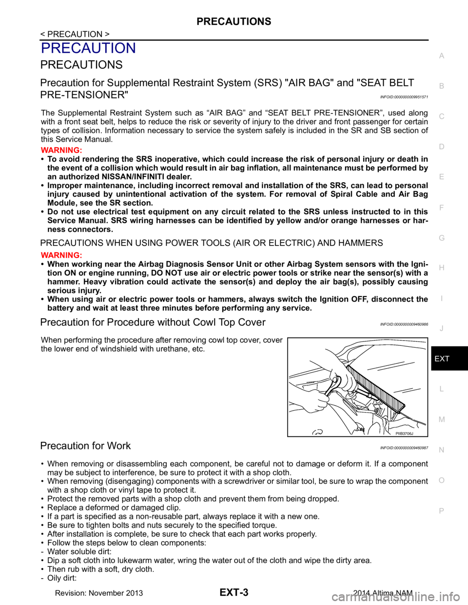
Precaution for Procedure without Cowl Top CoverINFOID:0000000009460986
When performing the procedure after removing cowl top cover, cover
the lower end of windshield with urethane, etc.
Precaution for WorkINFOID:0000000009460987
• When removing or disassembling each component, be ca reful not to damage or deform it. If a component
may be subject to interference, be sure to protect it with a shop cloth.
• When removing (disengaging) components with a screwdriver or similar tool, be sure to wrap the component with a shop cloth or vinyl tape to protect it.
• Protect the removed parts with a shop cloth and prevent them from being dropped.
• Replace a deformed or damaged clip.
• If a part is specified as a non-reusabl e part, always replace it with a new one.
• Be sure to tighten bolts and nuts securely to the specified torque.
• After installation is complete, be sure to check that each part works properly.
• Follow the steps below to clean components:
- Water soluble dirt:
• Dip a soft cloth into lukewarm water, wring the water out of the cloth and wipe the dirty area.
• Then rub with a soft, dry cloth.
-Oily dirt:
PIIB3706J
Revision: November 20132014 Altima NAM
Page 2431 of 4801
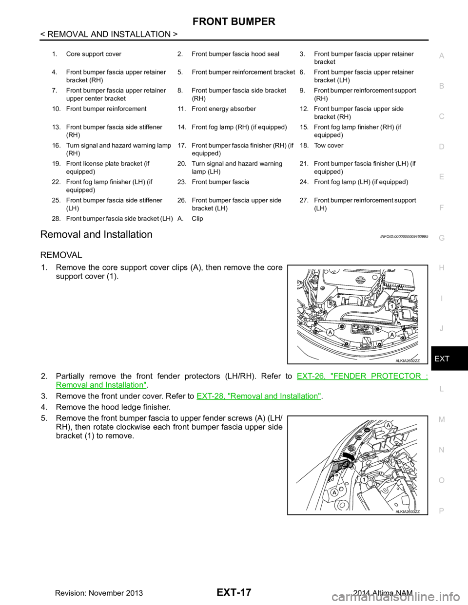
FRONT BUMPEREXT-17
< REMOVAL AND INSTALLATION >
C
D E
F
G H
I
J
L
M A
B
EXT
N
O P
Removal and InstallationINFOID:0000000009460995
REMOVAL
1. Remove the core support cover clips (A), then remove the core support cover (1).
2. Partially remove the front fender protectors (LH/RH). Refer to EXT-26, "FENDER PROTECTOR :
Removal and Installation".
3. Remove the front under cover. Refer to EXT-28, "Removal and Installation"
.
4. Remove the hood ledge finisher.
5. Remove the front bumper fascia to upper fender screws (A) (LH/ RH), then rotate clockwise each front bumper fascia upper side
bracket (1) to remove.
1. Core support cover 2. Front bumper fascia hood seal 3. Front bumper fascia upper retainer
bracket
4. Front bumper fascia upper retainer bracket (RH) 5. Front bumper reinforcement bracket 6. Front bumper fascia upper retainer
bracket (LH)
7. Front bumper fascia upper retainer upper center bracket 8. Front bumper fascia side bracket
(RH) 9. Front bumper reinforcement support
(RH)
10. Front bumper reinforcement 11. Front energy absorber 12. Front bumper fascia upper side bracket (RH)
13. Front bumper fascia side stiffener (RH) 14. Front fog lamp (RH) (if equipped) 15. Front fog lamp finisher (RH) (if
equipped)
16. Turn signal and hazard warning lamp (RH) 17. Front bumper fascia finisher (RH) (if
equipped) 18. Tow cover
19. Front license plate bracket (if equipped) 20. Turn signal and hazard warning
lamp (LH) 21. Front bumper fascia finisher (LH) (if
equipped)
22. Front fog lamp finisher (LH) (if equipped) 23. Front bumper fascia 24. Front fog lamp (LH) (if equipped)
25. Front bumper fascia side stiffener (LH) 26. Front bumper fascia upper side
bracket (LH) 27. Front bumper reinforcement support
(LH)
28. Front bumper fascia side bracket (LH) A. Clip
ALKIA2602ZZ
ALKIA2603ZZ
Revision: November 20132014 Altima NAM
Page 2432 of 4801
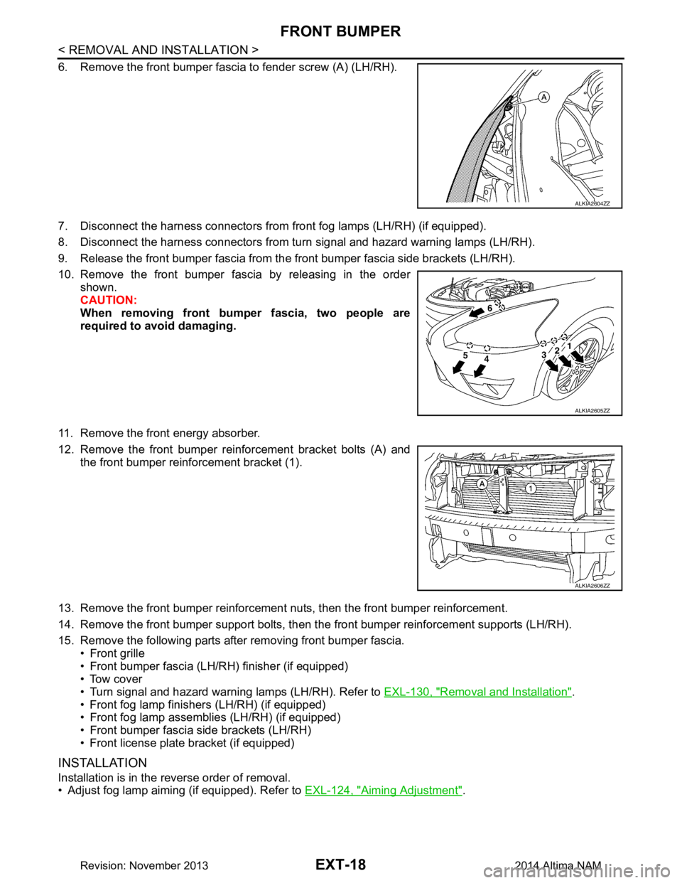
EXT-18
< REMOVAL AND INSTALLATION >
FRONT BUMPER
6. Remove the front bumper fascia to fender screw (A) (LH/RH).
7. Disconnect the harness connectors from front fog lamps (LH/RH) (if equipped).
8. Disconnect the harness connectors from turn signal and hazard warning lamps (LH/RH).
9. Release the front bumper fascia from the front bumper fascia side brackets (LH/RH).
10. Remove the front bumper fascia by releasing in the order shown.
CAUTION:
When removing front bumper fascia, two people are
required to avoid damaging.
11. Remove the front energy absorber.
12. Remove the front bumper reinforcement bracket bolts (A) and the front bumper reinforcement bracket (1).
13. Remove the front bumper reinforcement nuts, then the front bumper reinforcement.
14. Remove the front bumper support bolts, then t he front bumper reinforcement supports (LH/RH).
15. Remove the following parts after removing front bumper fascia. • Front grille
• Front bumper fascia (LH/RH) finisher (if equipped)
• Tow cover
• Turn signal and hazard warning lamps (LH/RH). Refer to EXL-130, "Removal and Installation"
.
• Front fog lamp finishers (LH/RH) (if equipped)
• Front fog lamp assemblies (LH/RH) (if equipped)
• Front bumper fascia side brackets (LH/RH)
• Front license plate bracket (if equipped)
INSTALLATION
Installation is in the reverse order of removal.
• Adjust fog lamp aiming (if equipped). Refer to EXL-124, "Aiming Adjustment"
.
ALKIA2604ZZ
ALKIA2605ZZ
ALKIA2606ZZ
Revision: November 20132014 Altima NAM
Page 2454 of 4801
FAX-2
< PRECAUTION >
PRECAUTIONS
PRECAUTION
PRECAUTIONS
Precaution for Supplemental Restraint System (SRS) "AIR BAG" and "SEAT BELT
PRE-TENSIONER"
INFOID:0000000009951700
The Supplemental Restraint System such as “A IR BAG” and “SEAT BELT PRE-TENSIONER”, used along
with a front seat belt, helps to reduce the risk or severi ty of injury to the driver and front passenger for certain
types of collision. Information necessary to service the system safely is included in the SR and SB section of
this Service Manual.
WARNING:
• To avoid rendering the SRS inopera tive, which could increase the risk of personal injury or death in
the event of a collision which would result in air bag inflation, all maintenance must be performed by
an authorized NISS AN/INFINITI dealer.
• Improper maintenance, including in correct removal and installation of the SRS, can lead to personal
injury caused by unintent ional activation of the system. For re moval of Spiral Cable and Air Bag
Module, see the SR section.
• Do not use electrical test equipmen t on any circuit related to the SRS unless instructed to in this
Service Manual. SRS wiring harn esses can be identified by yellow and/or orange harnesses or har-
ness connectors.
PRECAUTIONS WHEN USING POWER TOOLS (AIR OR ELECTRIC) AND HAMMERS
WARNING:
• When working near the Airbag Diagnosis Sensor Unit or other Airbag System sensors with the Igni-
tion ON or engine running, DO NOT use air or electri c power tools or strike near the sensor(s) with a
hammer. Heavy vibration could activate the sensor( s) and deploy the air bag(s), possibly causing
serious injury.
• When using air or electric power tools or hammers , always switch the Ignition OFF, disconnect the
battery and wait at least three minutes before performing any service.
Precautions for Drive ShaftINFOID:0000000009464432
Observe the following precautions when disassembling and assembling drive shaft.
• Joint sub-assembly does not disass emble because it is non-overhaul parts.
• Perform work in a location which is as dust-free as possible.
• Before disassembling and assembling, clean the outside of parts.
• Prevention of the entry of foreign objects must be tak en into account during disassembly of the service loca-
tion.
• Disassembled parts must be carefully reassembled in the correct order. If work is interrupted, a clean cover must be placed over parts.
• Paper shop cloths must be used. Fabric shop cloths must not be used because of the danger of lint adhering
to parts.
• Disassembled parts (except for rubber parts) should be cleaned with kerosene which shall be removed by
blowing with air or wiping with paper shop cloths.
Revision: November 20132014 Altima NAM
Page 2482 of 4801
FL-2
< PRECAUTION >
PRECAUTIONS
PRECAUTION
PRECAUTIONS
Precaution for Supplemental Restraint System (SRS) "AIR BAG" and "SEAT BELT
PRE-TENSIONER"
INFOID:0000000009951691
The Supplemental Restraint System such as “A IR BAG” and “SEAT BELT PRE-TENSIONER”, used along
with a front seat belt, helps to reduce the risk or severi ty of injury to the driver and front passenger for certain
types of collision. Information necessary to service the system safely is included in the SR and SB section of
this Service Manual.
WARNING:
• To avoid rendering the SRS inopera tive, which could increase the risk of personal injury or death in
the event of a collision which would result in air bag inflation, all maintenance must be performed by
an authorized NISS AN/INFINITI dealer.
• Improper maintenance, including in correct removal and installation of the SRS, can lead to personal
injury caused by unintent ional activation of the system. For re moval of Spiral Cable and Air Bag
Module, see the SR section.
• Do not use electrical test equipmen t on any circuit related to the SRS unless instructed to in this
Service Manual. SRS wiring harn esses can be identified by yellow and/or orange harnesses or har-
ness connectors.
PRECAUTIONS WHEN USING POWER TOOLS (AIR OR ELECTRIC) AND HAMMERS
WARNING:
• When working near the Airbag Diagnosis Sensor Unit or other Airbag System sensors with the Igni-
tion ON or engine running, DO NOT use air or electri c power tools or strike near the sensor(s) with a
hammer. Heavy vibration could activate the sensor( s) and deploy the air bag(s), possibly causing
serious injury.
• When using air or electric power tools or hammers , always switch the Ignition OFF, disconnect the
battery and wait at least three minutes before performing any service.
General PrecautionINFOID:0000000009460597
WARNING:
When replacing fuel line parts, be sure to observe the following.
• Put a “CAUTION: FLAMMABLE” sign in the work area.
• Be sure to work in a well ventilated area and have a CO
2 fire extinguisher.
• Do not smoke while working on the fuel system. Keep open flames and sparks away from the work
area.
CAUTION:
• Before removing fuel line parts, carry out the following procedures:
- Put drained fuel in an explosi on-proof container and put the lid on securely. Keep the container in
safe area.
- Release fuel pressure from the fuel lines. Refer to EC-182, "Work Procedure"
(QR25DE), EC-687,
"Work Procedure" (VQ35DE).
- Disconnect the battery ground cable.
• Always replace O-rings and clamps with new ones.
• Do not kink or twist tubes when they are being installed.
• Do not tighten hose clamps excessi vely to avoid damaging hoses.
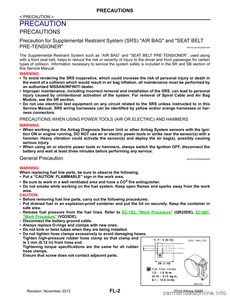
Tighten high-pressure rubber hose clamp so that clamp end
is 3 mm (0.12 in) from hose end.
Tightening torque specificati ons are the same for all rubber
hose clamps.
Ensure that screw does not contact adjacent parts.
MMA104A
Revision: November 20132014 Altima NAM