2014 NISSAN TEANA warning
[x] Cancel search: warningPage 2269 of 4801

EXL-3
C
D E
F
G H
I
J
K
M A
B
EXL
N
O P
Description ..........................................................
..
119
Diagnosis Procedure .............................................119
PARKING, LICENSE PLATE AND TAIL
LAMPS ARE NOT TURNED ON .................... ..
120
Description .......................................................... ..120
Diagnosis Procedure .............................................120
BOTH SIDE FRONT FOG LAMPS ARE NOT
TURNED ON ................................................... ..
121
Description .......................................................... ..121
Diagnosis Procedure .............................................121
PERIODIC MAINTENANCE .......................122
HEADLAMP .................................................... ..122
Aiming Adjustment .............................................. ..122
FRONT FOG LAMP ..........................................124
Aiming Adjustment .............................................. ..124
REMOVAL AND INSTALLATION .............126
FRONT COMBINATION LAMP ...................... ..126
Exploded View - Xenon ....................................... ..126
Removal and Installation - Xenon .........................126
Bulb Replacement - Xenon ...................................127
Exploded View - Halogen ......................................128
Removal and Installation - Halogen ......................128
Bulb Replacement - Halo gen ................................129
TURN SIGNAL AND HAZARD WARNING
LAMPS ........................................................... ..
130
Removal and Installation .......................................130
Bulb Replacement ........ .........................................130
FRONT FOG LAMP ........................................ ..131
Removal and Installation .......................................131
Bulb Replacement ........ .........................................131
DOOR MIRROR TURN SIGNAL LAMP ......... ..133
Removal and Installation .......................................133
Bulb Replacement ........ .........................................133
HIGH-MOUNTED STOP LAMP ......................134
Removal and Installation ..................................... ..134
Bulb Replacement .................................................134
LICENSE PLATE LAMP .................................135
Removal and Installation .......................................135
Bulb Replacement .................................................135
REAR COMBINATION LAMP .........................136
Exploded View .......................................................136
Removal and Installation .......................................137
Bulb Replacement .................................................138
COMBINATION SWITCH ................................139
Exploded View .......................................................139
Removal and Installation .......................................139
HAZARD SWITCH ..........................................140
Removal and Installation .......................................140
OPTICAL SENSOR .........................................141
Removal and Installation .......................................141
UNIT DISASSEMBLY AND ASSEMBLY ..142
FRONT COMBINATION LAMP ......................142
Exploded View - Xenon ....................................... ..142
Disassembly and Assembly - Xenon .....................142
Exploded View - Halogen ......................................143
Disassembly and Assembly - Halogen ..................143
REAR COMBINATION LAMP .........................145
Exploded View - Non LED .....................................145
Disassembly and Assembly - Non LED .................145
Exploded View - LED .............................................146
Disassembly and Assembly - LED ........................146
SERVICE DATA AND SPECIFICATIONS
(SDS) ............... ...........................................
148
SERVICE DATA AND SPECIFICATIONS
(SDS) ...............................................................
148
Bulb Specifications .............................................. ..148
Revision: November 20132014 Altima NAMRevision: November 20132014 Altima NAM
Page 2270 of 4801
EXL-4
< PRECAUTION >
PRECAUTIONS
PRECAUTION
PRECAUTIONS
Precaution for Supplemental Restraint System (SRS) "AIR BAG" and "SEAT BELT
PRE-TENSIONER"
INFOID:0000000009951582
The Supplemental Restraint System such as “A IR BAG” and “SEAT BELT PRE-TENSIONER”, used along
with a front seat belt, helps to reduce the risk or severi ty of injury to the driver and front passenger for certain
types of collision. Information necessary to service the system safely is included in the SR and SB section of
this Service Manual.
WARNING:
• To avoid rendering the SRS inopera tive, which could increase the risk of personal injury or death in
the event of a collision which would result in air bag inflation, all maintenance must be performed by
an authorized NISS AN/INFINITI dealer.
• Improper maintenance, including in correct removal and installation of the SRS, can lead to personal
injury caused by unintent ional activation of the system. For re moval of Spiral Cable and Air Bag
Module, see the SR section.
• Do not use electrical test equipmen t on any circuit related to the SRS unless instructed to in this
Service Manual. SRS wiring harn esses can be identified by yellow and/or orange harnesses or har-
ness connectors.
PRECAUTIONS WHEN USING POWER TOOLS (AIR OR ELECTRIC) AND HAMMERS
WARNING:
• When working near the Airbag Diagnosis Sensor Unit or other Airbag System sensors with the Igni-
tion ON or engine running, DO NOT use air or electri c power tools or strike near the sensor(s) with a
hammer. Heavy vibration could activate the sensor( s) and deploy the air bag(s), possibly causing
serious injury.
• When using air or electric power tools or hammers , always switch the Ignition OFF, disconnect the
battery and wait at least three minutes before performing any service.
General precautions fo r service operationsINFOID:0000000009463538
• Do not work with wet hands.
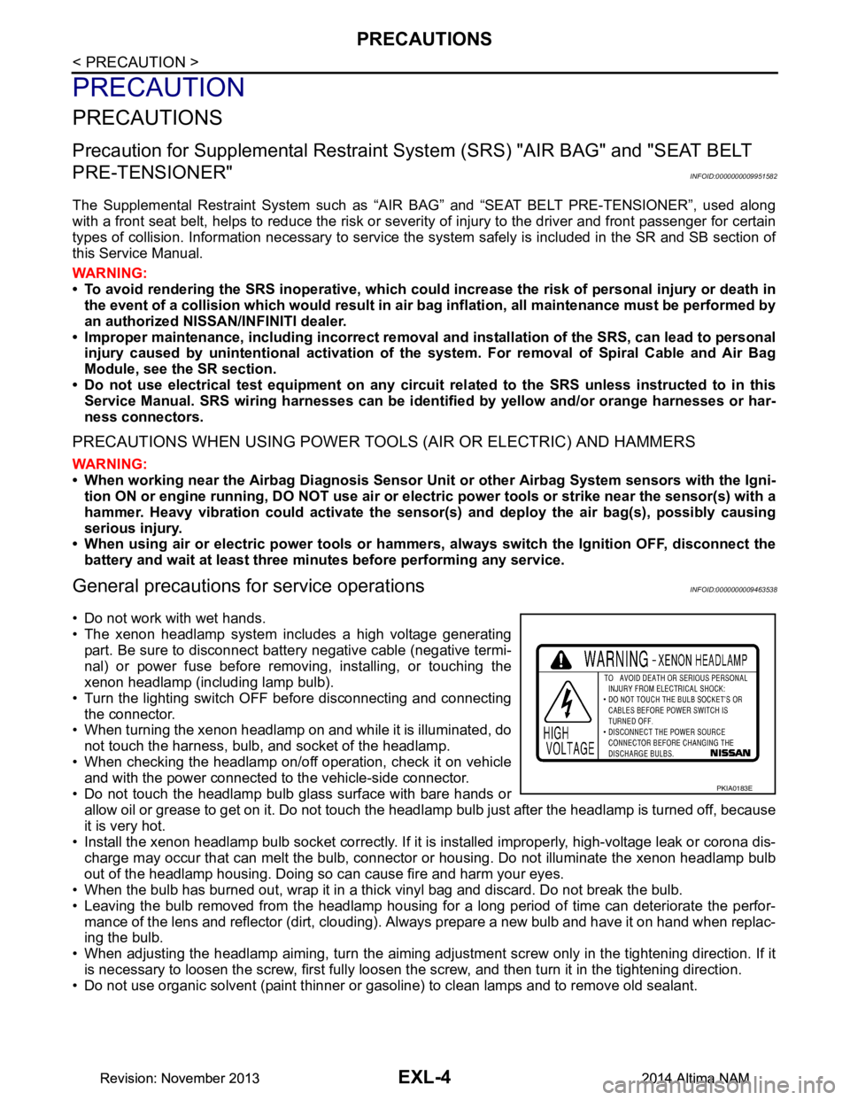
• The xenon headlamp system includes a high voltage generating
part. Be sure to disconnect batte ry negative cable (negative termi-
nal) or power fuse before removing, installing, or touching the
xenon headlamp (including lamp bulb).
• Turn the lighting switch OFF before disconnecting and connecting the connector.
• When turning the xenon headlamp on and while it is illuminated, do
not touch the harness, bulb, and socket of the headlamp.
• When checking the headlamp on/off operation, check it on vehicle and with the power connected to the vehicle-side connector.
• Do not touch the headlamp bulb glass surface with bare hands or allow oil or grease to get on it. Do not touch the headl amp bulb just after the headlamp is turned off, because
it is very hot.
• Install the xenon headlamp bulb socket co rrectly. If it is installed improperly, high-voltage leak or corona dis-
charge may occur that can melt the bulb, connector or housing. Do not illuminate the xenon headlamp bulb
out of the headlamp housing. Doing so can cause fire and harm your eyes.
• When the bulb has burned out, wrap it in a thick vinyl bag and discard. Do not break the bulb.
• Leaving the bulb removed from the headlamp housing for a long period of time can deteriorate the perfor- mance of the lens and reflector (dirt, clouding). Al ways prepare a new bulb and have it on hand when replac-
ing the bulb.
• When adjusting the headlamp aiming, turn the aiming adjus tment screw only in the tightening direction. If it
is necessary to loosen the screw, first fully loosen the screw, and then turn it in the tightening direction.
• Do not use organic solvent (paint thinner or gasoline) to clean lamps and to remove old sealant.
PKIA0183E
Revision: November 20132014 Altima NAMRevision: November 20132014 Altima NAM
Page 2277 of 4801
SYSTEMEXL-11
< SYSTEM DESCRIPTION >
C
D E
F
G H
I
J
K
M A
B
EXL
N
O P
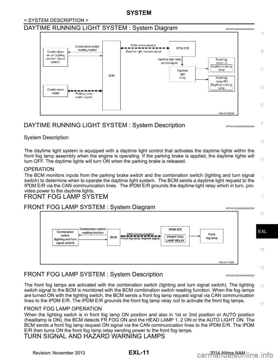
DAYTIME RUNNING LIGHT SY STEM : System DiagramINFOID:0000000009463547
DAYTIME RUNNING LIGHT SYST EM : System DescriptionINFOID:0000000009463548
System Description
The daytime light system is equipped with a daytime light control that activates the daytime lights within the
front fog lamp assembly when the engine is operating. If the parking brake is applied, the daytime lights will
turn OFF. The daytime lights will turn ON when the parking brake is released.
OPERATION
The BCM monitors inputs from the parking brake swit ch and the combination switch (lighting and turn signal
switch) to determine when to operate the daytime light s ystem. The BCM sends a daytime light request to the
IPDM E/R via the CAN communication lines. The IPDM E/ R grounds the daytime light relay which in turn, pro-
vides power to the daytime lights.
FRONT FOG LAMP SYSTEM
FRONT FOG LAMP SYSTEM : System DiagramINFOID:0000000009463549
FRONT FOG LAMP SYSTEM : System DescriptionINFOID:0000000009463550
The front fog lamps are activated with the combination switch (lighting and turn signal switch). The lighting
switch signal to the BCM is monitored with the BCM combination switch reading function. When the fog lamps
are turned ON with the lighting switch, the BCM sends a front fog lamp request signal via CAN communication
lines to the IPDM E/R. The IPDM E/R grounds the front fog lamp relay coil to activate the front fog lamps.
FRONT FOG LAMP OPERATION
When the lighting switch is in front fog lamp ON position and also in 1st or 2nd position or AUTO position
(headlamp is ON), the BCM detects FR FOG ON and the HEAD LAMP 1, 2 ON or the AUTO LIGHT ON. The
BCM sends a front fog lamp request ON signal via the CAN communication lines to the IPDM E/R. The IPDM
E/R then turns ON the front fog lamp re lay sending power to the front fog lamps.
TURN SIGNAL AND HAZARD WARNING LAMPS
AWLIA1965GB
AWLIA1719GB
Revision: November 20132014 Altima NAMRevision: November 20132014 Altima NAM
Page 2278 of 4801
EXL-12
< SYSTEM DESCRIPTION >
SYSTEM
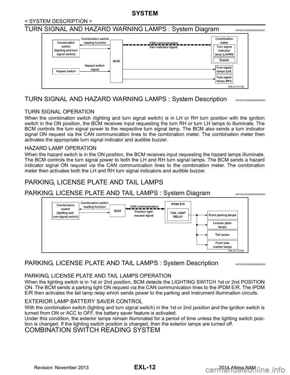
TURN SIGNAL AND HAZARD WARNI NG LAMPS : System Diagram
INFOID:0000000009463551
TURN SIGNAL AND HAZARD WARNING LAMPS : System DescriptionINFOID:0000000009463552
TURN SIGNAL OPERATION
When the combination switch (lighting and turn signal swit ch) is in LH or RH turn position with the ignition
switch in the ON position, the BCM receives input reques ting the turn RH or turn LH lamps to illuminate. The
BCM controls the turn signal power to the respective turn signal lamp. The BCM also sends a turn indicator
signal ON request via the CAN communication lines to the combination meter. The combination meter then
activates the appropriate turn signal indicator and audible buzzer.
HAZARD LAMP OPERATION
When the hazard switch is in the ON position, the BC M receives input requesting the hazard lamps illuminate.
The BCM controls the turn signal power to both the LH and RH turn signal lamps. The BCM sends a hazard
indicator signal ON request via the CAN communication lines to the combination meter. The combination
meter then activates both the LH and RH turn signal indicators and audible buzzer.
PARKING, LICENSE PLATE AND TAIL LAMPS
PARKING, LICENSE PLATE AND TAIL LAMPS : System DiagramINFOID:0000000009463553
PARKING, LICENSE PLATE AND TA IL LAMPS : System DescriptionINFOID:0000000009463554
PARKING, LICENSE PLATE AND TAIL LAMPS OPERATION
When the lighting switch is in 1st or 2nd position, BCM detects the LIGHTING SWITCH 1st or 2nd POSITION
ON. The BCM sends a parking light ON request via the CAN communication lines to the IPDM E/R. The IPDM
E/R then activates the tail lamp relay which sends power to the parking and instrument illumination circuits.
EXTERIOR LAMP BATTERY SAVER CONTROL
With the combination switch (lighting and turn signal switch) in the 1st or 2nd position and the ignition switch is
turned from ON or ACC to OFF, the battery saver feature is activated.
Under this condition, the exterior lamps remain illumi nated for a period of time unless the lighting switch posi-
tion is changed. If the lighting switch position is changed, then the exterior lamps are turned off.
COMBINATION SWITCH READING SYSTEM
AWLIA1721GB
AWLIA1723GB
Revision: November 20132014 Altima NAMRevision: November 20132014 Altima NAM
Page 2283 of 4801

DIAGNOSIS SYSTEM (BCM)EXL-17
< SYSTEM DESCRIPTION >
C
D E
F
G H
I
J
K
M A
B
EXL
N
O P
DIAGNOSIS SYSTEM (BCM)
COMMON ITEM
COMMON ITEM : CONSULT Function (BCM - COMMON ITEM)INFOID:0000000009956424
CAUTION:
After disconnecting the CONSULT vehicle interface (VI) from the data link connector, the ignition must
be cycled OFF → ON (for at least 5 seconds) → OFF. If this step is not performed, the BCM may not go
to ”sleep mode”, potentiall y causing a discharged battery and a no-start condition.
APPLICATION ITEM
CONSULT performs the following functions via CAN communication with BCM.
SYSTEM APPLICATION
BCM can perform the following functions.
Direct Diagnostic Mode Description
Ecu Identification The BCM part number is displayed.
Self Diagnostic Result The BCM self diagnostic results are displayed.
Data Monitor The BCM input/output data is displayed in real time.
Active Test The BCM activates outputs to test components.
Work support The settings for BCM functions can be changed.
Configuration • The vehicle specification can be read and saved.
• The vehicle specification can be written when replacing BCM.
CAN Diag Support Mntr The result of transmit/receive diagnosis of CAN communication is displayed.
System Sub System Direct Diagnostic Mode
Ecu Identification
Self Diagnostic Result
Data Monitor
Active Test
Work support
Configuration
CAN Diag Su pport Mntr
Door lock DOOR LOCK ××××
Rear window defogger REAR DEFOGGER ×××
Warning chime BUZZER ××
Interior room lamp timer INT LAMP ×××
Remote keyless entry system MULTI REMOTE ENT ×××
Exterior lamp HEADLAMP ×××
Wiper and washer WIPER ×××
Turn signal and hazard warning lamps FLASHER ××
Air conditioner AIR CONDITIONER ×
Intelligent Key system INTELLIGENT KEY ××××
Combination switch COMB SW ×
BCM BCM × × ×××
Immobilizer IMMU ×××
Interior room lamp battery saver BATTERY SAVER ××
Trunk open TRUNK ×
Vehicle security system THEFT ALM ×××
Revision: November 20132014 Altima NAMRevision: November 20132014 Altima NAM
Page 2290 of 4801

EXL-24
< SYSTEM DESCRIPTION >
DIAGNOSIS SYSTEM (IPDM E/R)
APPLICATION ITEM
CONSULT performs the following functions via CAN communication with IPDM E/R.
ECU IDENTIFICATION
The IPDM E/R part number is displayed.
SELF DIAGNOSTIC RESULT
Refer to PCS-20, "DTC Index".
DATA MONITOR
Direct Diagnostic Mode Description
Ecu Identification The IPDM E/R part number is displayed.
Self Diagnostic Result The IPDM E/R self diagnostic results are displayed.
Data Monitor The IPDM E/R input/output data is displayed in real time.
Active Test The IPDM E/R activates outputs to test components.
CAN Diag Support Mntr The result of transmit/receive diagnosis of CAN communication is displayed.
Monitor Item [Unit] Main
Signals Description
MOTOR FAN REQ [%] ×Indicates cooling fan speed signal received from ECM on CAN communication
line
AC COMP REQ [On/Off] ×Indicates A/C compressor request signal received from ECM on CAN commu-
nication line
TAIL&CLR REQ [On/Off] ×Indicates position light request signal received from BCM on CAN communica-
tion line
HL LO REQ [On/Off] ×Indicates low beam request signal received from BCM on CAN communication
line
HL HI REQ [On/Off] ×Indicates high beam request signal received from BCM on CAN communication
line
FR FOG REQ [On/Off] ×Indicates front fog light request signal received from BCM on CAN communica-
tion line
FR WIP REQ [Stop/1LOW/Low/Hi] ×Indicates front wiper request signal received from BCM on CAN communication
line
WIP AUTO STOP [STOP P/ACT P] ×Indicates condition of front wiper auto stop signal
WIP PROT [Off/BLOCK] ×Indicates condition of front wiper fail-safe operation
IGN RLY1 -REQ [On/Off] Indicates ignition switch ON signal received from BCM on CAN communication
line
IGN RLY [On/Off] ×Indicates condition of ignition relay
PUSH SW [On/Off] Indicates condition of push-button ignition switch
INTER/NP SW [On/Off] Indicates condition of CVT shift position
ST RLY CONT [On/Off] Indicates starter relay status signal received from BCM on CAN communication
line
IHBT RLY -REQ [On/Off] Indicates starter control relay signal received from BCM on CAN communication
line
ST/INHI RLY [Off/ ST /INHI] Indicates condition of starter relay and starter control relay
DETENT SW [On/Off] Indicates condition of CVT shift selector (park position switch)
DTRL REQ [Off] Indicates daytime light request signal received from BCM on CAN communica-
tion line
HOOD SW [On/Off] Indicates condition of hood switch
THFT HRN REQ [On/Off] Indicates theft warning horn request signal received from BCM on CAN commu-
nication line
Revision: November 20132014 Altima NAMRevision: November 20132014 Altima NAM
Page 2326 of 4801
EXL-60
< WIRING DIAGRAM >
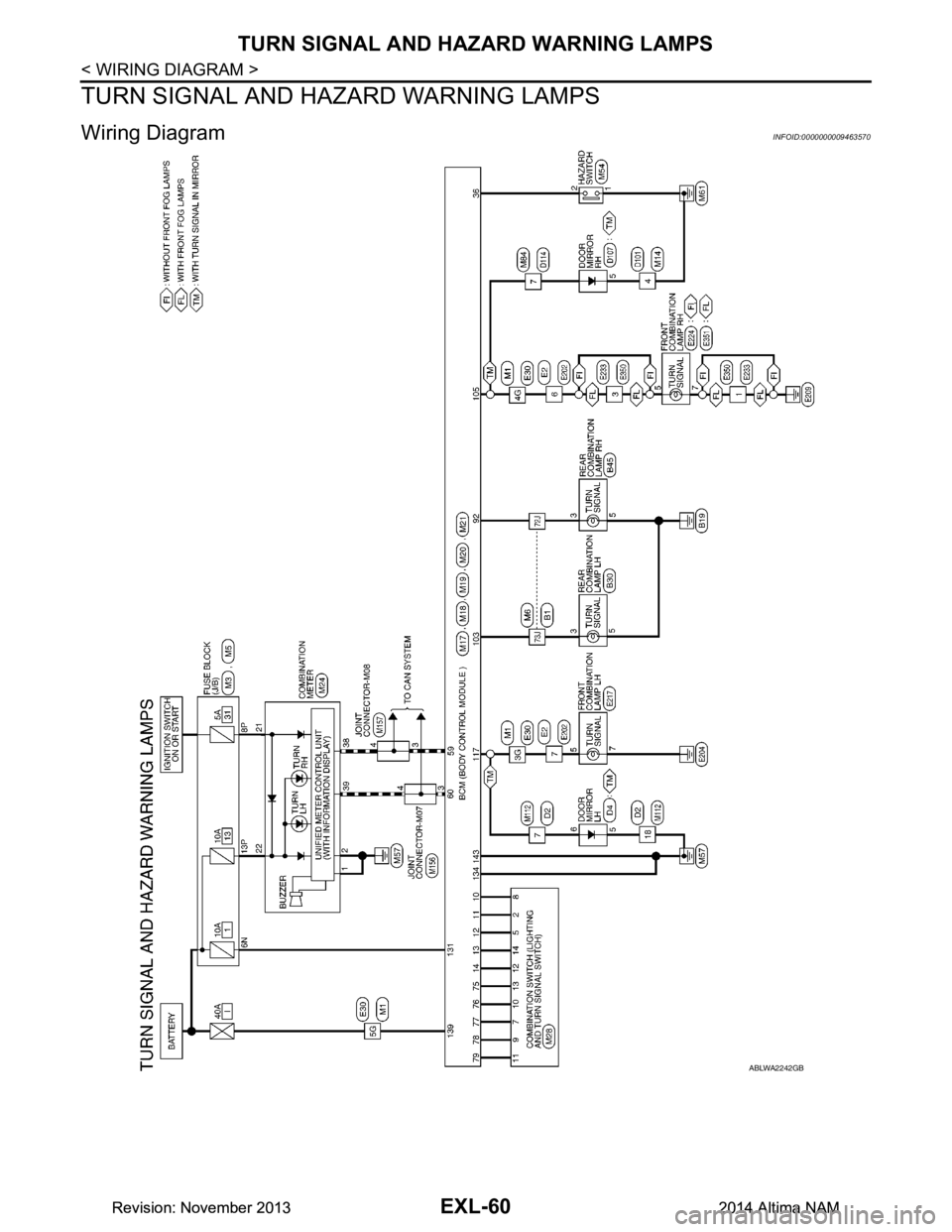
TURN SIGNAL AND HAZARD WARNING LAMPS
TURN SIGNAL AND HAZARD WARNING LAMPS
Wiring Diagram INFOID:0000000009463570
ABLWA2242GB
Revision: November 20132014 Altima NAMRevision: November 20132014 Altima NAM
Page 2327 of 4801
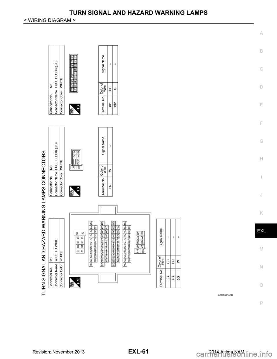
TURN SIGNAL AND HAZARD WARNING LAMPSEXL-61
< WIRING DIAGRAM >
C
D E
F
G H
I
J
K
M A
B
EXL
N
O P
ABLIA5164GB
Revision: November 20132014 Altima NAMRevision: November 20132014 Altima NAM