2014 NISSAN TEANA jacking points
[x] Cancel search: jacking pointsPage 2082 of 4801
![NISSAN TEANA 2014 Service Manual
EM-84
< UNIT REMOVAL AND INSTALLATION >[QR25DE]
ENGINE ASSEMBLY
Removal and Installation
INFOID:0000000009460508
WARNING:
• Place chocks at the front and back of the rear wheels.
• For engines n NISSAN TEANA 2014 Service Manual
EM-84
< UNIT REMOVAL AND INSTALLATION >[QR25DE]
ENGINE ASSEMBLY
Removal and Installation
INFOID:0000000009460508
WARNING:
• Place chocks at the front and back of the rear wheels.
• For engines n](/manual-img/5/57390/w960_57390-2081.png)
EM-84
< UNIT REMOVAL AND INSTALLATION >[QR25DE]
ENGINE ASSEMBLY
Removal and Installation
INFOID:0000000009460508
WARNING:
• Place chocks at the front and back of the rear wheels.
• For engines not equipped with slin gers, attach proper slingers and bolts as described in the Parts
Catalog.
CAUTION:
• Do not start working until the exh aust system and coolant are cool.
• If items or work required are not covered by the en gine main body section, follow the applicable pro-
cedures.
• Use the correct supporting points for lifting and jacking. Refer to GI-33, "Garage Jack and Safety
Stand".
• In removing the drive shaft, be careful not to damage the grease seals on the transaxle.
NOTE:
When removing components such as hoses, tubes/lines, etc. , cap or plug openings to prevent fluid from spill-
ing.
REMOVAL
1. Remove engine cover using power tool. Refer to EM-28, "Removal and Installation".
2. Release fuel pressure. Refer to EC-182, "Work Procedure"
.
3. Disconnect the negative and positive battery terminal. Refer to PG-73, "Removal and Installation (Bat-
tery)".
4. Disconnect the fuel rail at the fuel hose quick connector (engine side). Refer to EM-41, "Removal and
Installation".
5. Drain the engine coolant. Refer to CO-12, "Changing Engine Coolant"
.
6. Remove the engine under cover. Refer to EXT-28, "Removal and Installation"
.
7. Remove hood assembly. Refer to DLK-170, "HOOD ASSEMBLY : Removal and Installation"
.
8. Remove core support cover.
9. Remove the front air duct and air cleaner case assembly. Refer to EM-29, "Removal and Installation"
.
10. Remove battery and battery tray. Refer to PG-74, "Removal and Installation (Battery Tray)"
.
11. Remove cowl top. Refer to EXT-24, "Removal and Installation"
.
12. Remove strut brace. Refer to FSU-19, "Exploded View"
.
13. Disconnect EVAP hose and vacuum hose from intake manifold.
14. Remove upper and lower radiator hoses (engine side).
15. Remove CVT cooler lines.
16. Disconnect engine room harness connecto r at the CVT and ECM connectors.
CAUTION:
Protect the harness connector with plastic bags or suitable covering to help prevent damage and
intrusion of foreign mate rials into the connectors.
17. Remove the brake booster vacuum hose.
18. Disconnect the heater hoses.
19. Remove the front wheels and tires using a power tool. Refer to WT-55, "Adjustment"
.
20. Remove the fender protector side covers (RH) and (LH). Refer to EXT-26, "FENDER PROTECTOR :
Removal and Installation".
21. Remove tie rod ends from the steering knuckles. Refer to ST-36, "Removal and Installation"
.
22. Remove the power steering gear bolts and support the power steering gear. Refer to ST-36, "Exploded
View".
23. Remove rear cover plate.
24. Remove the torque converter nuts.
25. Remove the rear engine mount torque rod.
26. Remove front exhaust tube and gaskets. Refer to EX-5, "Exploded View"
.
G. 90 N·m (9.2 kg-m, 66 ft-lb) H. 103 N·m (11 kg-m, 76 ft-lb) J. Follow installation procedure
Front
Revision: November 20132014 Altima NAM
Page 2218 of 4801
![NISSAN TEANA 2014 Service Manual
EM-220
< UNIT REMOVAL AND INSTALLATION >[VQ35DE]
ENGINE ASSEMBLY
UNIT REMOVAL AND INSTALLATION
ENGINE ASSEMBLY
Exploded ViewINFOID:0000000009460579
Removal and InstallationINFOID:0000000009460580
WAR NISSAN TEANA 2014 Service Manual
EM-220
< UNIT REMOVAL AND INSTALLATION >[VQ35DE]
ENGINE ASSEMBLY
UNIT REMOVAL AND INSTALLATION
ENGINE ASSEMBLY
Exploded ViewINFOID:0000000009460579
Removal and InstallationINFOID:0000000009460580
WAR](/manual-img/5/57390/w960_57390-2217.png)
EM-220
< UNIT REMOVAL AND INSTALLATION >[VQ35DE]
ENGINE ASSEMBLY
UNIT REMOVAL AND INSTALLATION
ENGINE ASSEMBLY
Exploded ViewINFOID:0000000009460579
Removal and InstallationINFOID:0000000009460580
WARNING:
• Place chocks at front and back of rear wheels.
• For engines not equipped with en gine slingers, attach proper slingers and bolts as described in the
NISSAN Parts Catalog.
• Do not start working until exhau st system and coolant are cool.
CAUTION:
• If items or work required are not covered by the en gine main body section, follow the applicable pro-
cedures.
• Use the correct supporting points for lifting and jacking. Refer to GI-33, "Garage Jack and Safety
Stand".
• In removing the drive shafts, be careful not to damage any transaxle grease seals.
• Before separating the engine and transaxle, remove the crankshaft position sensor (POS).
AWBIA1341ZZ
1. Engine mounting bracket (rear) 2. Rear torque rod 3. Rear torque rod bracket
4. Upper torque rod 5. Engine mounting bracket (RH) 6. Engine mounting insulator (RH)
7. Engine mounting insulator (front) 8. Front engine mounting insulator vac- uum hose9. Engine mounting bracket (front)
10. Engine mounting insulator (LH) 11. Engine mounting insulator (rear) 12. Rear engine mounting insulator vac- uum hose
13. Gusset Front
Revision: November 20132014 Altima NAM
Page 2555 of 4801

PRECAUTIONSGI-27
< PRECAUTION >
C
D E
F
G H
I
J
K L
M B
GI
N
O P
• Install the xenon bulb secure ly. (Insufficient bulb socket
installation may melt the bu lb, the connector, the housing,
etc, by high-voltage leakage or corona discharge.)
• Never perform HID circuit inspection with a tester.
• Never touch the xenon bulb gl ass with hands. Never put oil
and grease on it.
• Dispose of the used xenon bulb after packing it in thick vinyl
without breaking it.
• Never wipe out dirt and contam ination with organic solvent
(thinner, gasoline, etc.).
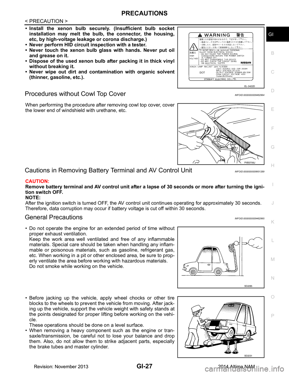
Procedures without Cowl Top CoverINFOID:0000000009462994
When performing the procedure after removing cowl top cover, cover
the lower end of windshield with urethane, etc.
Cautions in Removing Battery Terminal and AV Control UnitINFOID:0000000009951289
CAUTION:
Remove battery terminal and AV control unit after a lapse of 30 seconds or more after turning the igni-
tion switch OFF.
NOTE:
After the ignition switch is turned OFF, the AV cont rol unit continues operating for approximately 30 seconds.
Therefore, data corruption may occur if battery voltage is cut off within 30 seconds.
General PrecautionsINFOID:0000000009462995
• Do not operate the engine for an extended period of time without proper exhaust ventilation.
Keep the work area well ventilated and free of any inflammable
materials. Special care should be taken when handling any inflam-
mable or poisonous materials, such as gasoline, refrigerant gas,
etc. When working in a pit or ot her enclosed area, be sure to prop-
erly ventilate the area before working with hazardous materials.
Do not smoke while working on the vehicle.
• Before jacking up the vehicle, apply wheel chocks or other tire blocks to the wheels to prevent t he vehicle from moving. After jack-
ing up the vehicle, support the vehicle weight with safety stands at
the points designated for proper lifting before working on the vehi-
cle.
These operations should be done on a level surface.
• When removing a heavy component such as the engine or tran-
saxle/transmission, be careful not to lose your balance and drop
them. Also, do not allow them to strike adjacent parts, especially
the brake tubes and master cylinder.
EL-3422D
PIIB3706J
SGI285
SGI231
Revision: November 20132014 Altima NAMRevision: November 20132014 Altima NAM
Page 3723 of 4801

RSU-6
< PERIODIC MAINTENANCE >
REAR SUSPENSION ASSEMBLY
• Check the wheelarch height in the unladen condition. Refer to RSU-17, "Wheelarch Height (Unladen*1)".
GENERAL INFORMATION AND RECOMMENDATIONS
1. A Four-Wheel Thrust Alignment should be performed.
• This type of alignment is recommended for any NISSAN vehicle.
• The four-wheel “thrust” process helps ensure that the vehicle is properly aligned and the steering wheel
is centered.
• The alignment machine itself should be ca pable of accepting any NISSAN vehicle.
• The alignment machine should be checked to ensure that it is level.
2. Make sure the alignment machine is properly calibrated. • Your alignment machine should be regularly calibrated in order to give correct information.
• Check with the manufacturer of your specific al ignment machine for their recommended Service/Cali-
bration Schedule.
THE ALIGNMENT PROCESS
IMPORTANT: Use only the alignment specifications listed in this Service Manual. Refer to RSU-17,
"Wheelarch Height (Unladen*1)".
1. When displaying the alignment settings, many alignm ent machines use “indicators”: (Green/red, plus or
minus, Go/No Go). Do NOT use these indicators.
• The alignment specifications programmed into your alignment machine that operate these indicators
may not be correct.
• This may result in an ERROR.
2. Most camera-type alignment machines are equipped with both "Rolling Compensation" method and optional "Jacking Compensation" method to "com pensate" the alignment targets or head units.
"Rolling Compensation" is the preferred method.
• If using the "Rolling Compensation" method, after installing the alignment targets or head units, push or pull on the rear wheel to move the vehicle. Do not push or pull the vehicle body.
• If using the "Jacking Compensation" method, after in stalling the alignment targets or head units, raise
the vehicle and rotate the wheels 1/2 turn both ways.
NOTE:
Do not use the "Rolling Compensation" method if you are using sensor-type alignment equipment.
• Follow all instructions for the alignment machine you are using for more information.
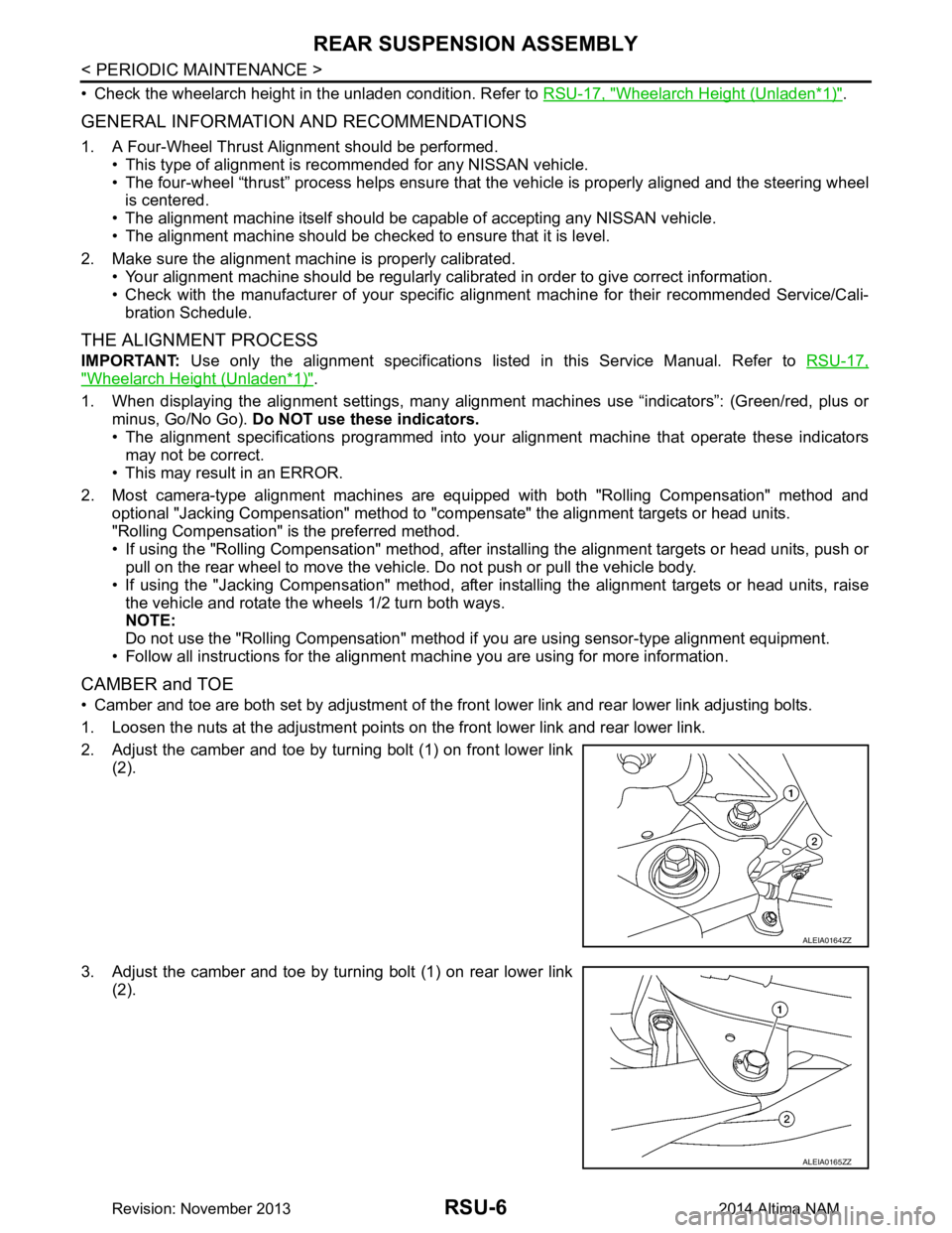
CAMBER and TOE
• Camber and toe are both set by adjustment of the fr ont lower link and rear lower link adjusting bolts.
1. Loosen the nuts at the adjustment points on the front lower link and rear lower link.
2. Adjust the camber and toe by turning bolt (1) on front lower link (2).
3. Adjust the camber and toe by turning bolt (1) on rear lower link (2).
ALEIA0164ZZ
ALEIA0165ZZ
Revision: November 20132014 Altima NAM