2014 NISSAN TEANA warning
[x] Cancel search: warningPage 2543 of 4801

ABBREVIATIONSGI-15
< HOW TO USE THIS MANUAL >
C
D E
F
G H
I
J
K L
M B
GI
N
O P
I
K
L
M
N
O
ABBREVIATION DESCRIPTION I/M Inspection and maintenanceIA Intake air
IAC Idle air control IAT Intake air temperature
IBA Intelligent brake assist IC Ignition control
ICC Intelligent cruise control
ICM Ignition control module
IPDM E/R Intelligent power distribution module engine room ISC Idle speed controlISS Input shaft speed ITS Information technology suite
ABBREVIATION DESCRIPTION KS Knock sensor
ABBREVIATION DESCRIPTION LBC Li-ion battery controller
LCD Liquid crystal display
LCU Local control unit LDP Lane departure prevention
LDW Lane departure warning LED Light emitting diode LH Left-hand
LIN Local interconnect network
ABBREVIATION DESCRIPTION M/T Manual transaxle/transmission
MAF Mass airflow
MAP Manifold absolute pressure
MDU Multi display unit MI Malfunction indicator
MIL Malfunction indicator lamp
MOD Moving object detection
ABBREVIATION DESCRIPTION NOX Nitrogen oxides
ABBREVIATION DESCRIPTION O2 Oxygen
O2S Oxygen sensor
OBD On board diagnostic OC Oxidation catalytic converter
OD Overdrive
Revision: November 20132014 Altima NAMRevision: November 20132014 Altima NAM
Page 2554 of 4801
GI-26
< PRECAUTION >
PRECAUTIONS
PRECAUTION
PRECAUTIONS
DescriptionINFOID:0000000009462991
Observe the following precautions to ensure safe and proper servicing. These precautions are not
described in each individual section.
Precaution for Supplemental Restraint Syst em (SRS) "AIR BAG" and "SEAT BELT
PRE-TENSIONER"
INFOID:0000000009462992
The Supplemental Restraint System such as “A IR BAG” and “SEAT BELT PRE-TENSIONER”, used along
with a front seat belt, helps to reduce the risk or severi ty of injury to the driver and front passenger for certain
types of collision. Information necessary to service the system safely is included in the SR and SB section of
this Service Manual.
WARNING:
• To avoid rendering the SRS inopera tive, which could increase the risk of personal injury or death in
the event of a collision which would result in air bag inflation, all maintenance must be performed by
an authorized NISS AN/INFINITI dealer.
• Improper maintenance, including in correct removal and installation of the SRS, can lead to personal
injury caused by unintent ional activation of the system. For re moval of Spiral Cable and Air Bag
Module, see the SR section.
• Do not use electrical test equipmen t on any circuit related to the SRS unless instructed to in this
Service Manual. SRS wiring harn esses can be identified by yellow and/or orange harnesses or har-
ness connectors.
PRECAUTIONS WHEN USING POWER TOOLS (AIR OR ELECTRIC) AND HAMMERS
WARNING:
• When working near the Airbag Diagnosis Sensor Unit or other Airbag System sensors with the Igni-
tion ON or engine running, DO NOT use air or electri c power tools or strike near the sensor(s) with a
hammer. Heavy vibration could activate the sensor( s) and deploy the air bag(s), possibly causing
serious injury.
• When using air or electric power tools or hammers , always switch the Ignition OFF, disconnect the
battery and wait at least 3 minutes before performing any service.
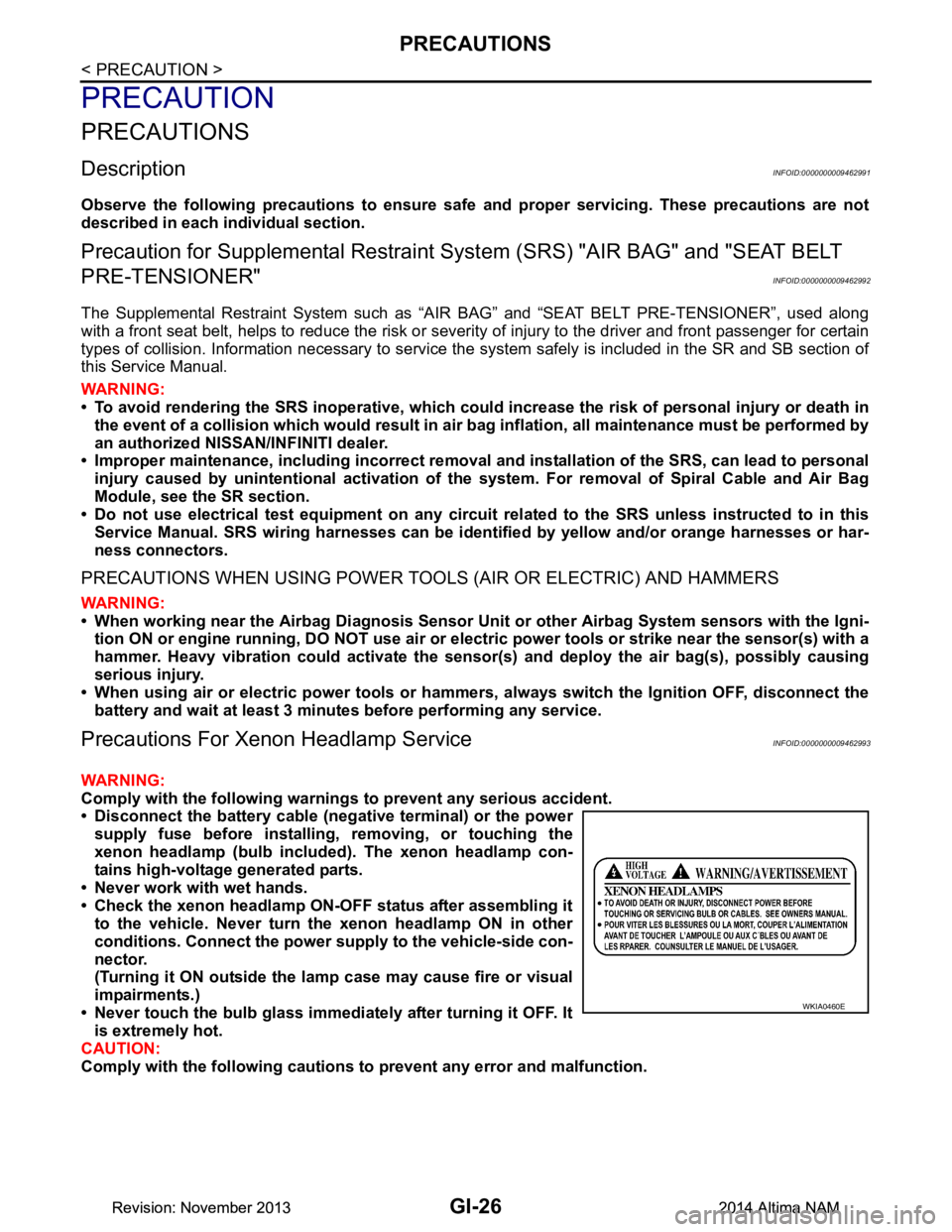
Precautions For Xeno n Headlamp ServiceINFOID:0000000009462993
WARNING:
Comply with the following warnings to prevent any serious accident.
• Disconnect the battery cable (n egative terminal) or the power
supply fuse before in stalling, removing, or touching the
xenon headlamp (bulb included) . The xenon headlamp con-
tains high-voltage generated parts.
• Never work with wet hands.
• Check the xenon headlamp ON-OFF status after assembling it to the vehicle. Never turn the xenon headlamp ON in other
conditions. Connect the power supply to the vehicle-side con-
nector.
(Turning it ON outside the la mp case may cause fire or visual
impairments.)
• Never touch the bulb glass immediately after turning it OFF. It is extremely hot.
CAUTION:
Comply with the following cautions to prevent any error and malfunction.
WKIA0460E
Revision: November 20132014 Altima NAMRevision: November 20132014 Altima NAM
Page 2556 of 4801
GI-28
< PRECAUTION >
PRECAUTIONS
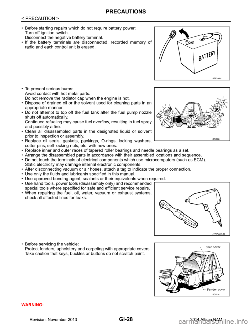
• Before starting repairs which do not require battery power:Turn off ignition switch.
Disconnect the negative battery terminal.
• If the battery terminals are disconnected, recorded memory of
radio and each control unit is erased.
• To prevent serious burns: Avoid contact with hot metal parts.
Do not remove the radiator cap when the engine is hot.
• Dispose of drained oil or the solvent used for cleaning parts in an
appropriate manner.
• Do not attempt to top off the fuel tank after the fuel pump nozzle
shuts off automatically.
Continued refueling may cause fuel overflow, resulting in fuel spray
and possibly a fire.
• Clean all disassembled parts in the designated liquid or solvent
prior to inspection or assembly.
• Replace oil seals, gaskets, packings, O-rings, locking washers, cotter pins, self-locking nuts, etc. with new ones.
• Replace inner and outer races of tapered roller bearings and needle bearings as a set.
• Arrange the disassembled parts in accordance with their assembled locations and sequence.
• Do not touch the terminals of electrical com ponents which use microcomputers (such as ECM).
Static electricity may damage internal electronic components.
• After disconnecting vacuum or air hoses, atta ch a tag to indicate the proper connection.
• Use only the fluids and lubricants specified in this manual.
• Use approved bonding agent, sealants or their equivalents when required.
• Use hand tools, power tools (disassembly only) and recommended special tools where specified for safe and efficient service repairs.
• When repairing the fuel, oil, water, vacuum or exhaust systems,
check all affected lines for leaks.
• Before servicing the vehicle: Protect fenders, upholstery and carpeting with appropriate covers.
Take caution that keys, buckles or buttons do not scratch paint.
WARNING:
SEF289H
SGI233
JPAIA0335ZZ
SGI234
Revision: November 20132014 Altima NAMRevision: November 20132014 Altima NAM
Page 2560 of 4801
GI-32
< PRECAUTION >
LIFTING POINT
LIFTING POINT
Special Service ToolINFOID:0000000009463003
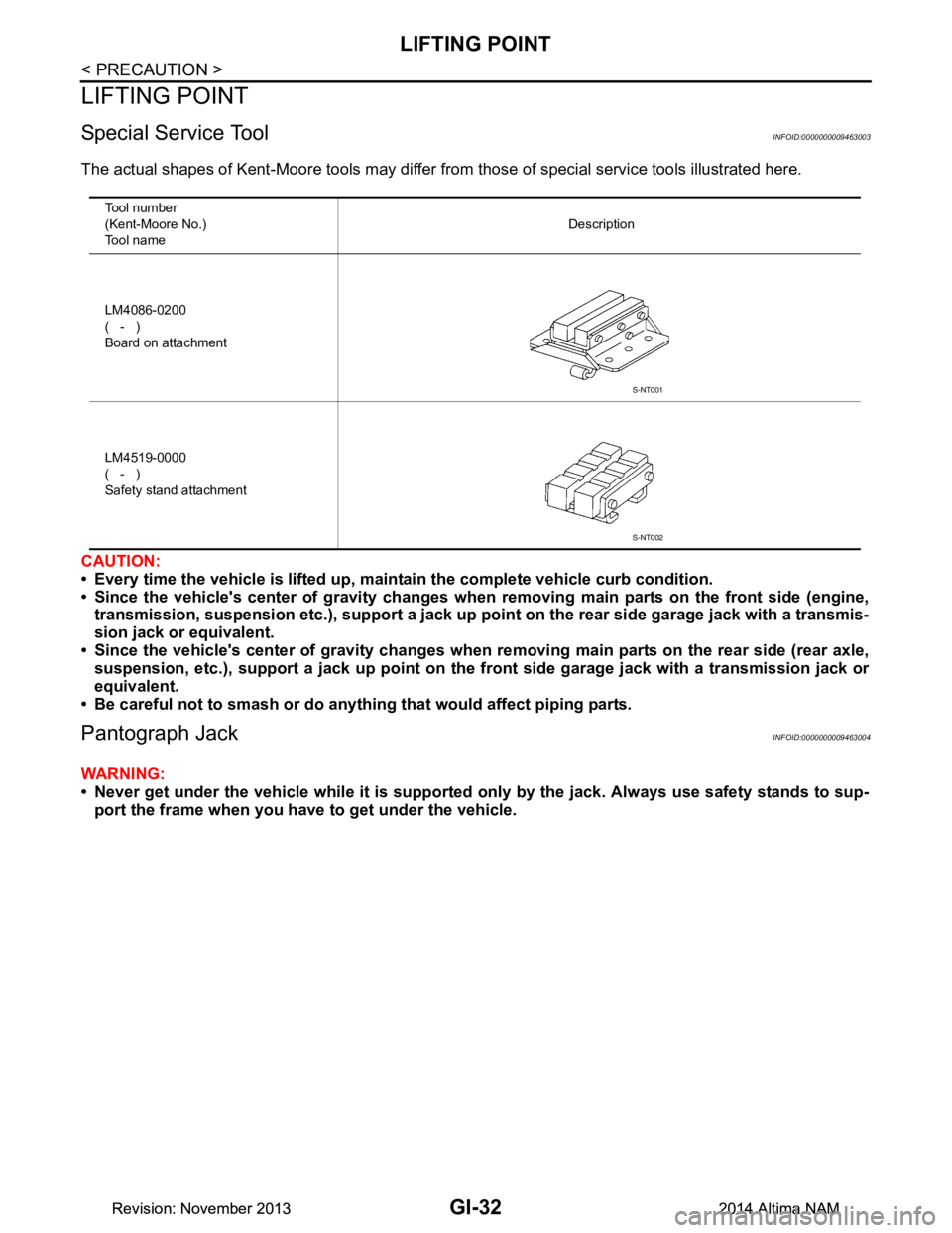
The actual shapes of Kent-Moore tools may differ from those of special service tools illustrated here.
CAUTION:
• Every time the vehicle is lifted up, main tain the complete vehicle curb condition.
• Since the vehicle's center of gravity changes when removing main parts on the front side (engine,
transmission, suspension etc.), supp ort a jack up point on the rear side garage jack with a transmis-
sion jack or equivalent.
• Since the vehicle's center of gravity changes when removing main parts on the rear side (rear axle,
suspension, etc.), support a jack up point on the front side garage jack with a transmission jack or
equivalent.
• Be careful not to smash or do anythi ng that would affect piping parts.
Pantograph JackINFOID:0000000009463004
WARNING:
• Never get under the vehicle while it is supported only by the jack. Always use safety stands to sup-
port the frame when you have to get under the vehicle.
Tool number
(Kent-Moore No.)
Tool name Description
LM4086-0200
( - )
Board on attachment
LM4519-0000
( - )
Safety stand attachment
S-NT001
S-NT002
Revision: November 20132014 Altima NAMRevision: November 20132014 Altima NAM
Page 2561 of 4801
LIFTING POINTGI-33
< PRECAUTION >
C
D E
F
G H
I
J
K L
M B
GI
N
O P
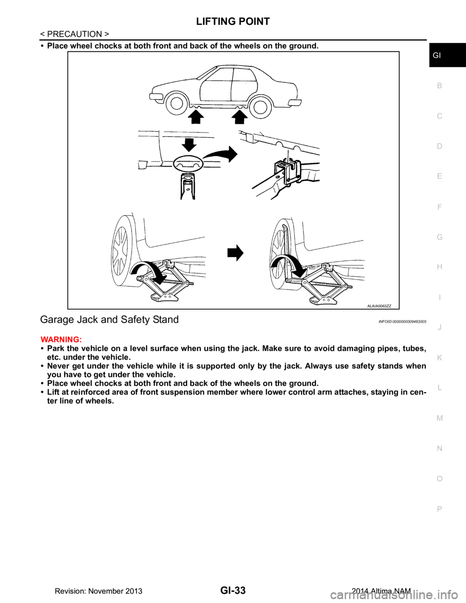
• Place wheel chocks at both front a nd back of the wheels on the ground.
Garage Jack and Safety StandINFOID:0000000009463005
WARNING:
• Park the vehicle on a level surface when using th e jack. Make sure to avoid damaging pipes, tubes,
etc. under the vehicle.
• Never get under the vehicle while it is supported only by the jack. Always use safety stands when
you have to get under the vehicle.
• Place wheel chocks at both front a nd back of the wheels on the ground.
• Lift at reinforced area of front suspension member where lower control arm attaches, staying in cen-
ter line of wheels.
ALAIA0063ZZ
Revision: November 20132014 Altima NAMRevision: November 20132014 Altima NAM
Page 2562 of 4801
GI-34
< PRECAUTION >
LIFTING POINT
2-Pole Lift
INFOID:0000000009463006
WARNING:
When lifting the vehicle, open the lift arms as wide as possible and ensure that the front and rear of the
vehicle are well balanced.
When setting the lift arm, do not allow the arm to contact the brake tubes, brake cable, fuel lines and
sill spoiler.
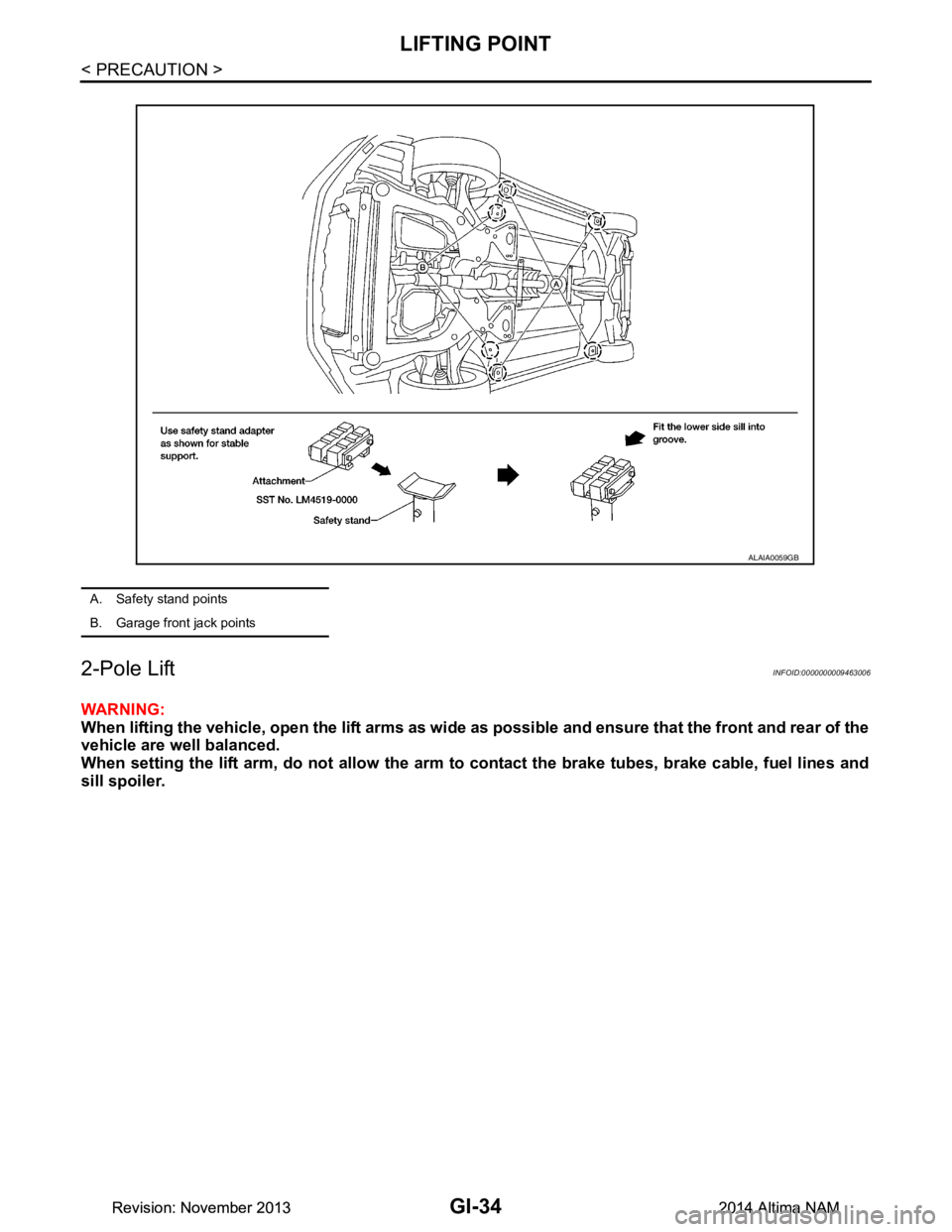
A. Safety stand points
B. Garage front jack points
ALAIA0059GB
Revision: November 20132014 Altima NAMRevision: November 20132014 Altima NAM
Page 2564 of 4801
GI-36
< PRECAUTION >
TOW TRUCK TOWING
TOW TRUCK TOWING
Tow Truck TowingINFOID:0000000009463008
CAUTION:
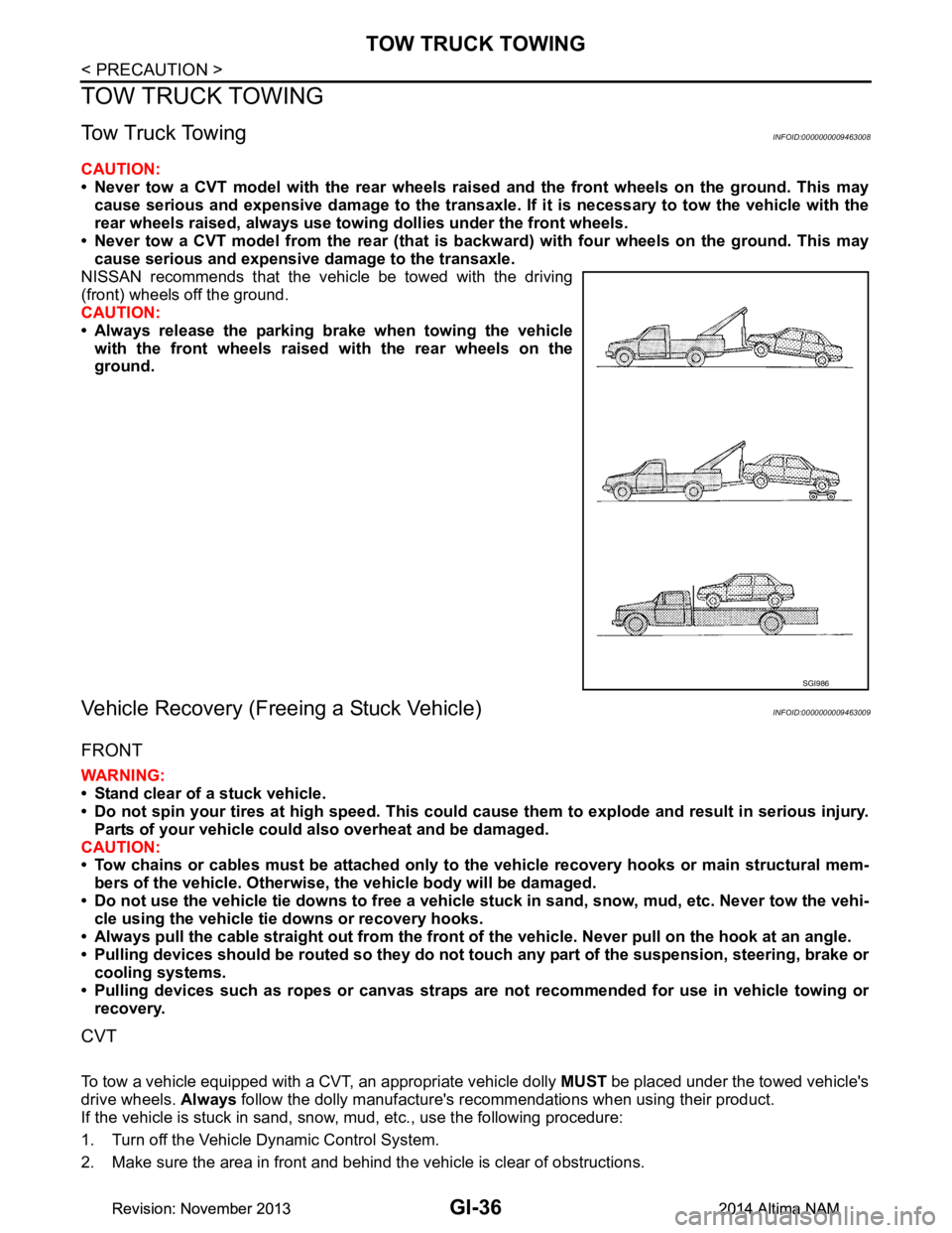
• Never tow a CVT model with the rear wheels raised and the front wheels on the ground. This may
cause serious and expensive damage to the transaxle. If it is necessary to tow the vehicle with the
rear wheels raised, always use towi ng dollies under the front wheels.
• Never tow a CVT model from the rear (that is backw ard) with four wheels on the ground. This may
cause serious and expensive damage to the transaxle.
NISSAN recommends that the vehicle be towed with the driving
(front) wheels off the ground.
CAUTION:
• Always release the parking brake when towing the vehicle with the front wheels raised with the rear wheels on the
ground.
Vehicle Recovery (Freeing a Stuck Vehicle)INFOID:0000000009463009
FRONT
WARNING:
• Stand clear of a stuck vehicle.
• Do not spin your tires at high speed. This could cause them to explode and result in serious injury.
Parts of your vehicle could also overheat and be damaged.
CAUTION:
• Tow chains or cables must be attached only to the vehicle recovery hooks or main structural mem-
bers of the vehicle. Otherwise, the vehicle body will be damaged.
• Do not use the vehicle tie downs to free a vehicle stuck in sand, snow, mud, etc. Never tow the vehi-
cle using the vehicle tie downs or recovery hooks.
• Always pull the cable straight out from the front of the vehicle. Never pull on the hook at an angle.
• Pulling devices should be routed so they do not touch any part of the suspension, steering, brake or
cooling systems.
• Pulling devices such as ropes or canvas straps ar e not recommended for use in vehicle towing or
recovery.
CVT
To tow a vehicle equipped with a CVT, an appropriate vehicle dolly MUST be placed under the towed vehicle's
drive wheels. Always follow the dolly manufacture's recommendations when using their product.
If the vehicle is stuck in sand, snow , mud, etc., use the following procedure:
1. Turn off the Vehicle Dynamic Control System.
2. Make sure the area in front and behind the vehicle is clear of obstructions.
SGI986
Revision: November 20132014 Altima NAMRevision: November 20132014 Altima NAM
Page 2579 of 4801
CONSULT CHECKING SYSTEMGI-51
< BASIC INSPECTION >
C
D E
F
G H
I
J
K L
M B
GI
N
O PCONSULT CHECKING SYSTEM
DescriptionINFOID:0000000009463016
CAUTION:
After disconnecting the CONSULT vehicle interface (VI) from the data link connector, the ignition must
be cycled OFF → ON (for at least 5 seconds) → OFF. If this step is not performed, the BCM may not go
to “sleep mode”, potentiall y causing a discharged battery and a no-start condition.
NOTE:
This vehicle is diagnosed using the CONSULT-III plus.
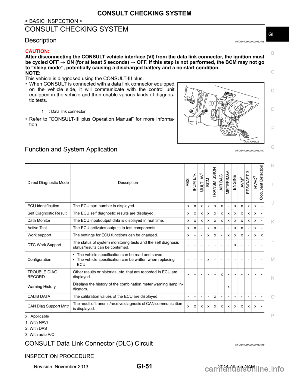
• When CONSULT is connected with a data link connector equipped on the vehicle side, it will communicate with the control unit
equipped in the vehicle and then enable various kinds of diagnos-
tic tests.
• Refer to “CONSULT-III plus Operation Manual” for more informa- tion.
Function and System ApplicationINFOID:0000000009463017
x : Applicable
1: With NAVI
2: With DAS
3: With auto A/C
CONSULT Data Link Connector (DLC) CircuitINFOID:0000000009463018
INSPECTION PROCEDURE
1 : Data link connector
ALAIA0061ZZ
Direct Diagnostic Mode DescriptionABS
IPDM E/R
MULTI AV
1
BCM
TRANSMISSION
AIR BAG
METER/M&A
ENGINE
AV M
2
EPS/DAST 3 HVAC
3
Occupant Detection
ECU identification The ECU part number is displayed. x x x x x x - x x x x -
Self Diagnostic Result The ECU self diagnostic results are displayed. x x x x x x x x x x x -
Data Monitor The ECU input/output data is displayed in real time. x x x x x x x x x x x -
Active Test The ECU activates outputs to test components. x x - x x - - x x - x -
Work support The settings for ECU functions can be changed. x - - x x - x x x - x x
DTC Work Support The status of system monitoring tests and the self diagnosis
status/results can be confirmed. -------x----
Configuration • The vehicle specification can be read and saved.
• The vehicle specification can be written when replacing ECU. ---x--------
TROUBLE DIAG
RECORD Other results or histories, etc. that are recorded in ECU are
displayed. -----x------
Warning History Displays the history of the combination meter warning lamp in-
dicators. ------x-----
CALIB DATA The calibration values of the ECU are displayed. - - - - x - - - - - - -
CAN Diag Support Mntr The result of transmit/receive diagnosis of CAN communication
is displayed. xxxxxxxxxxx-
Revision: November 20132014 Altima NAMRevision: November 20132014 Altima NAM