2014 NISSAN TEANA parking sensors
[x] Cancel search: parking sensorsPage 3263 of 4801

MWI-8
< SYSTEM DESCRIPTION >
COMPONENT PARTS
Unit Description
Combination meter Controls the following with the signals received from each unit via CAN communication and the signals
from switches and sensors:
• Speedometer
• Tachometer
• Engine coolant temperature gauge
• Fuel gauge
• Warning lamps
• Indicator lamps
• Meter illumination control
• Meter effect function
• Information display
Meter control switch Transmits the following signals to the combination meter:
• Trip reset switch signal
• Illumination control switch signal (+)
• Illumination control switch signal ( −)
ECM Transmits the following signals to the combination meter via CAN communication:
• Engine speed signal
• Engine coolant temperature signal
• Engine oil pressure warning signal
• Fuel consumption monitor signal
ABS actuator and electric unit
(control unit) Transmits the vehicle speed signal to the combination meter via CAN communication.
Power steering control module Transmits the EPS signal to the combination meter via CAN communication.
BCM Transmits the following signals to the combination meter via CAN communication:
• Tire pressure information
• Position light request signal
• Low tire pressure warning lamp signal
• Door switch signal
• Trunk lamp switch signal
TCM Receives the O/D OFF switch signal from the combination meter via CAN communication.
Transmits the O/D OFF indicator request signal to the combination meter via CAN communication.
CVT shift selector switch
(overdrive co ntrol switch)
(with QR25DE) Transmits the O/D OFF switch signal to the combination meter
Fuel level sensor unit Transmits the fuel level sensor signal to the combination meter.
Seat belt buckle switch LH
(RH similar) Transmits the seat belt buckle switch LH signal to the combination meter.
Air bag diagnosis sensor unit Transmits the following signals to the combination meter:
• Seat belt buckle switch RH signal
• Air bag warning indicator
Engine oil pressure sensor Transmits the engine oil pressure sensor signal to the ECM.
Ambient sensor Transmits the ambient sensor signal to the IPDM E/R.
A/C auto amp. • Receives the ambient sensor signal from the IPDM E/R (with auto A/C).
• Transmits the ambient sensor signal to the combination meter via CAN communication.
Parking brake switch Transmits the parking brake switch signal to the combination meter.
Washer fluid level switch Transmits the washer fluid level switch signal to the combination meter.
Steering switch Transmits the following signals to the information display:
• Display signal
• Menu up signal
• Menu down signal
• Enter signal
• Back signal
IPDM E/R • Receives the ambient sensor signal from the ambient sensor.
• Transmits the ambient sensor signal to the combination meter (without auto A/C).
• Transmits the ambient sensor signal to the A/C auto amp (with auto A/C).
Brake fluid level switch Transmits the brake fluid level switch signal to the combination meter.
Revision: November 20132014 Altima NAMRevision: November 20132014 Altima NAM
Page 3355 of 4801
![NISSAN TEANA 2014 Service Manual
PC S-6
< SYSTEM DESCRIPTION >[IPDM E/R]
SYSTEM
RELAY CONTROL SYSTEM : System Description
INFOID:0000000009461598
IPDM E/R activates the internal cont rol circuit to perform the relay ON-OFF control a NISSAN TEANA 2014 Service Manual
PC S-6
< SYSTEM DESCRIPTION >[IPDM E/R]
SYSTEM
RELAY CONTROL SYSTEM : System Description
INFOID:0000000009461598
IPDM E/R activates the internal cont rol circuit to perform the relay ON-OFF control a](/manual-img/5/57390/w960_57390-3354.png)
PC S-6
< SYSTEM DESCRIPTION >[IPDM E/R]
SYSTEM
RELAY CONTROL SYSTEM : System Description
INFOID:0000000009461598
IPDM E/R activates the internal cont rol circuit to perform the relay ON-OFF control according to the input sig-
nals from various sensors and the request signals received from control units via CAN communication.
CAUTION:
IPDM E/R integrated relays cannot be removed.
POWER CONSUMPTION CONTROL SYSTEM
Control relay Input/output T ransmit unitControl partReference
page
Front fog lamp relay Front fog lamp request signal BCM (CAN) Front fog lamp EXL-101
Headlamp high relay High beam request signal BCM (CAN) Headlamp highEXL-91
Headlamp low relay Low beam request signal BCM (CAN) Headlamp lowEXL-93
(halogen)
EXL-94
(xe-
non)
Tail lamp relay Position light request signal BCM (CAN) •Parking lamp
• Side marker lamp
• License plate lamp
•Tail lamp EXL-103
• Front wiper relay
• Front wiper high relay Front wiper request signal BCM (CAN)
Front wiperWW-48
Front wiper auto stop signal Front wiper motor
Cooling fan relay-1 Cooling fan request signal ECM Cooling fan EC-499
(QR25DE)
EC-953
(VQ35DE)
A/C relay A/C compressor request signal ECM (CAN) A/C compressor HAC-87
(automatic
air condi-
tioner)
HAC-151
(manual air
conditioner)
Ignition relay-1 Ignition switch ON signal BCM (CAN)
Ignition relay-1PCS-58
Vehicle speed signal Combination meter (CAN)
Push-button ignition switch Push-button ignition switch
Fuel pump relay Fuel pump request signal ECM Fuel pump EC-508
(QR25DE)
EC-965
(VQ35DE)
ECM relay ECM relay cont rol signal ECM ECM relay EC-203
(QR25DE)
EC-709
(VQ35DE)
Throttle contro l motor relay Throttle control
motor relay sig-
nal ECMThrottle control motor re-
lay EC-475
(QR25DE)
EC-933
(VQ35DE)
Starter relay Starter relay control signal BCM Starter motor PCS-12
Starter control relay
Revision: November 20132014 Altima NAMRevision: November 20132014 Altima NAM
Page 4154 of 4801

PRECAUTIONSSTC-3
< PRECAUTION >
C
D E
F
H I
J
K L
M A
B
STC
N
O P
PRECAUTION
PRECAUTIONS
Precaution for Supplemental Restraint System (SRS) "AIR BAG" and "SEAT BELT
PRE-TENSIONER"
INFOID:0000000009951730
The Supplemental Restraint System such as “A IR BAG” and “SEAT BELT PRE-TENSIONER”, used along
with a front seat belt, helps to reduce the risk or severi ty of injury to the driver and front passenger for certain
types of collision. Information necessary to service t he system safely is included in the SR and SB section of
this Service Manual.
WARNING:
• To avoid rendering the SRS inoper ative, which could increase the risk of personal injury or death in
the event of a collision which would result in air bag inflation, all maintenance must be performed by
an authorized NISSAN/INFINITI dealer.
• Improper maintenance, including in correct removal and installation of the SRS, can lead to personal
injury caused by unintentional act ivation of the system. For removal of Spiral Cable and Air Bag
Module, see the SR section.
• Do not use electrical test equipm ent on any circuit related to the SRS unless instructed to in this
Service Manual. SRS wiring harnesses can be identi fied by yellow and/or orange harnesses or har-
ness connectors.
PRECAUTIONS WHEN USING POWER TOOLS (AIR OR ELECTRIC) AND HAMMERS
WARNING:
• When working near the Airbag Diagnosis Sensor Un it or other Airbag System sensors with the Igni-
tion ON or engine running, DO NOT use air or el ectric power tools or strike near the sensor(s) with a
hammer. Heavy vibration could activate the sensor( s) and deploy the air bag(s), possibly causing
serious injury.
• When using air or electric power tools or hammers , always switch the Ignition OFF, disconnect the
battery and wait at least three mi nutes before performing any service.
Service Notice and Precautions for Hydrau lic Pump Electric Power Steering System
INFOID:0000000009460340
• Check each tire for proper air pressure and size. Refer to WT-60, "Tire".
• Verify that the steering system components are G enuine NISSAN parts and have been installed properly.
• Check the steering column for loose mounting bolts.
• Check the steering gear assembly for loose mounting bolts. Check the inner sockets and outer sockets for
damage or wear. Inspect the boots and seals for leakage of power steering fluid.
• Verify proper wheel alignment. Refer to FSU-7, "Inspection and Adjustment"
.
• Check for any damage, wear, or modification to the suspension and body that would result in increased
weight or an improper wheelarch height. Refer to FSU-26, "Wheelarch Height (Unladen*
1)".
• Check for proper battery voltage.
• Verify that all power steering pump assembly connections are clean and fully seated.
• Verify that only Genuine NISSAN E-PSF is used. Use of any power steering fluid other than Genuine NIS-
SAN E-PSF will prevent the power st eering system from proper operation.
• An audible high pitch noise may be heard from the engine compartment when the steering wheel is oper-
ated, particularly at low speeds such as a parking lot maneuver. This condition is not a malfunction, rather
normal system operation. Steering at low speeds or parking lot maneuvers demands higher hydraulic assis-
tance, resulting in larger power st eering pump load and increased system noise.
• The power steering pump is electrically controlled by the power steering control module.
• Before connecting or disconnecting the power steeri ng control module harness connectors, turn ignition
switch “OFF” and disconnect battery ground cable. Batter y voltage is applied to power steering control mod-
ule even if ignition switch is turned “OFF”.
Revision: November 20132014 Altima NAMRevision: November 20132014 Altima NAM
Page 4701 of 4801

WT-26
< BASIC INSPECTION >
ID REGISTRATION PROCEDURE
5. Turn on the Signal Tech II tool (J-50190).
6. Hold the Signal Tech II against the side of the left front tire, near the valve stem.
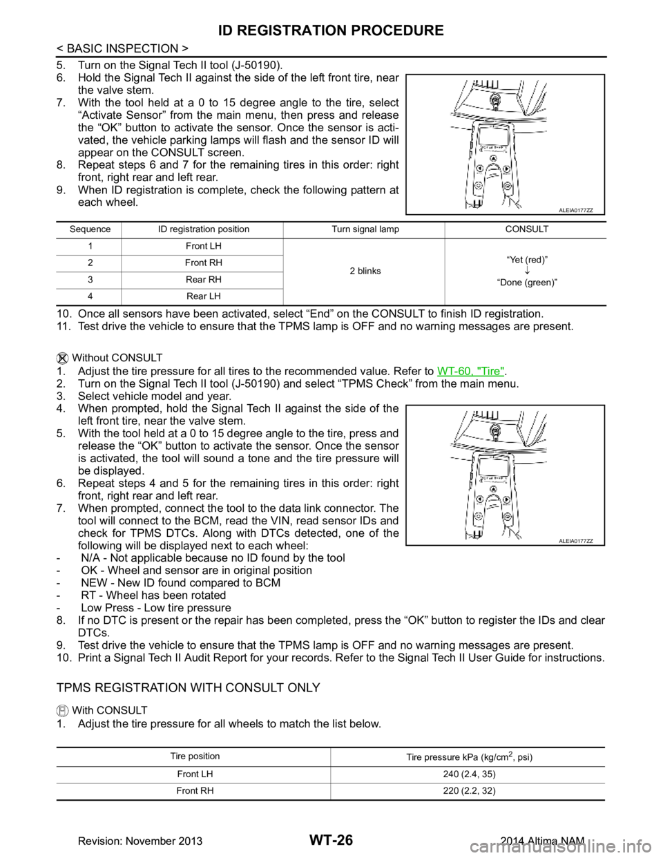
7. With the tool held at a 0 to 15 degree angle to the tire, select
“Activate Sensor” from the main menu, then press and release
the “OK” button to activate the s ensor. Once the sensor is acti-
vated, the vehicle parking lamps will flash and the sensor ID will
appear on the CONSULT screen.
8. Repeat steps 6 and 7 for the remaining tires in this order: right
front, right rear and left rear.
9. When ID registration is complete, check the following pattern at each wheel.
10. Once all sensors have been activated, select “End” on the CONSULT to finish ID registration.
11. Test drive the vehicle to ensure that the TPMS lamp is OFF and no warning messages are present.
Without CONSULT
1. Adjust the tire pressure for all tires to the recommended value. Refer to WT-60, "Tire".
2. Turn on the Signal Tech II tool (J-50190) and select “TPMS Check” from the main menu.
3. Select vehicle model and year.
4. When prompted, hold the Signal Tech II against the side of the
left front tire, near the valve stem.
5. With the tool held at a 0 to 15 degree angle to the tire, press and release the “OK” button to activate the sensor. Once the sensor
is activated, the tool will sound a tone and the tire pressure will
be displayed.
6. Repeat steps 4 and 5 for the remaining tires in this order: right
front, right rear and left rear.
7. When prompted, connect the tool to the data link connector. The tool will connect to the BCM, read the VIN, read sensor IDs and
check for TPMS DTCs. Along wit h DTCs detected, one of the
following will be displayed next to each wheel:
- N/A - Not applicable because no ID found by the tool
- OK - Wheel and sensor are in original position
- NEW - New ID found compared to BCM
- RT - Wheel has been rotated
- Low Press - Low tire pressure
8. If no DTC is present or the repair has been complet ed, press the “OK” button to register the IDs and clear
DTCs.
9. Test drive the vehicle to ensure that the TPMS lamp is OFF and no warning messages are present.
10. Print a Signal Tech II Audit Report for your records. Re fer to the Signal Tech II User Guide for instructions.
TPMS REGISTRATION WITH CONSULT ONLY
With CONSULT
1. Adjust the tire pressure for all wheels to match the list below.
ALEIA0177ZZ
Sequence ID registration position Turn signal lamp CONSULT
1Front LH
2 blinks“Yet (red)”
↓
“Done (green)”
2Front RH
3Rear RH
4Rear LH
ALEIA0177ZZ
Tire position Tire pressure kPa (kg/cm2, psi)
Front LH 240 (2.4, 35)
Front RH 220 (2.2, 32)
Revision: November 20132014 Altima NAMRevision: November 20132014 Altima NAM