2014 NISSAN TEANA warning
[x] Cancel search: warningPage 2832 of 4801

DIAGNOSIS SYSTEM (BCM)INL-11
< SYSTEM DESCRIPTION >
C
D E
F
G H
I
J
K
M A
B
INL
N
O P
DIAGNOSIS SYSTEM (BCM)
COMMON ITEM
COMMON ITEM : CONSULT Function (BCM - COMMON ITEM)INFOID:0000000009956797
CAUTION:
After disconnecting the CONSULT vehicle interface (VI) from the data link connector, the ignition must
be cycled OFF → ON (for at least 5 seconds) → OFF. If this step is not performed, the BCM may not go
to ”sleep mode”, potentiall y causing a discharged battery and a no-start condition.
APPLICATION ITEM
CONSULT performs the following functions via CAN communication with BCM.
SYSTEM APPLICATION
BCM can perform the following functions.
Direct Diagnostic Mode Description
Ecu Identification The BCM part number is displayed.
Self Diagnostic Result The BCM self diagnostic results are displayed.
Data Monitor The BCM input/output data is displayed in real time.
Active Test The BCM activates outputs to test components.
Work support The settings for BCM functions can be changed.
Configuration • The vehicle specification can be read and saved.
• The vehicle specification can be written when replacing BCM.
CAN Diag Support Mntr The result of transmit/receive diagnosis of CAN communication is displayed.
System Sub System Direct Diagnostic Mode
Ecu Identification
Self Diagnostic Result
Data Monitor
Active Test
Work support
Configuration
CAN Diag Su pport Mntr
Door lock DOOR LOCK ××××
Rear window defogger REAR DEFOGGER ×××
Warning chime BUZZER ××
Interior room lamp timer INT LAMP ×××
Remote keyless entry system MULTI REMOTE ENT ×××
Exterior lamp HEADLAMP ×××
Wiper and washer WIPER ×××
Turn signal and hazard warning lamps FLASHER ××
Air conditioner AIR CONDITIONER ×
Intelligent Key system INTELLIGENT KEY ××××
Combination switch COMB SW ×
BCM BCM × × ×××
Immobilizer IMMU ×××
Interior room lamp battery saver BATTERY SAVER ××
Trunk open TRUNK ×
Vehicle security system THEFT ALM ×××
Revision: November 20132014 Altima NAMRevision: November 20132014 Altima NAM
Page 2836 of 4801
![NISSAN TEANA 2014 Service Manual
DIAGNOSIS SYSTEM (BCM)INL-15
< SYSTEM DESCRIPTION >
C
D E
F
G H
I
J
K
M A
B
INL
N
O P
ACTIVE TEST
WORK SUPPORT
DETE SW PWR [On/Off] Indicates condition of detent switch voltage.
ACC RLY -REQ [On/ NISSAN TEANA 2014 Service Manual
DIAGNOSIS SYSTEM (BCM)INL-15
< SYSTEM DESCRIPTION >
C
D E
F
G H
I
J
K
M A
B
INL
N
O P
ACTIVE TEST
WORK SUPPORT
DETE SW PWR [On/Off] Indicates condition of detent switch voltage.
ACC RLY -REQ [On/](/manual-img/5/57390/w960_57390-2835.png)
DIAGNOSIS SYSTEM (BCM)INL-15
< SYSTEM DESCRIPTION >
C
D E
F
G H
I
J
K
M A
B
INL
N
O P
ACTIVE TEST
WORK SUPPORT
DETE SW PWR [On/Off] Indicates condition of detent switch voltage.
ACC RLY -REQ [On/Off] Indicates condition of accessory relay control request.
RKE OPE COUN1 [0-19] ×When remote keyless entry receiver receives the signal transmitted while
operating on Intelligent Key, the numerical value start changing.
RKE OPE COUN2 [0-19] ×When remote keyless entry receiver receives the signal transmitted while
operating on Intelligent Key, the numerical value start changing.
TRNK/HAT MNTR [On/Off] Indicates condition of trunk room lamp switch.
RKE-LOCK [On/Off] Indicates condition of lock signal from Intelligent Key.
RKE-UNLOCK [On/Off] Indicates condition of unlock signal from Intelligent Key.
RKE-TR/BD [On/Off] Indicates condition of trunk open signal from Intelligent Key.
RKE-PANIC [On/Off] Indicates condition of panic signal from Intelligent Key.
RKE-MODE CHG [On/Off] Indicates condition of mode change signal from Intelligent Key. Monitor Item [Unit] Main Description
Test Item Description
INTELLIGENT KEY LINK (CAN) This test is able to check Intelligent Key iden
tification number [Off/ID No1/ID N02/ID No3/ID
No4/ID No5].
INT LAMP This test is able to check interior room lamp operation [On/Off].
FLASHER This test is able to check hazard lamp operation [LH/RH/Off].
HORN This test is able to check horn operation [On].
BATTERY SAVER This test is able to check battery saver operation [On/Off].
TRUNK/BACK DOOR This test is able to check trunk actuator operation [Open].
OUTSIDE BUZZER This test is able to check In telligent Key warning buzzer operation [On/Off].
INSIDE BUZZER This test is able to check combination meter warning chime operation [Take Out/Knob/Key/
Off].
INDICATOR This test is able to check combination meter warning lamp operation [KEY ON/KEY IND/Off].
IGN CONT2 This test is able to check ignition relay-2 control operation [On/Off].
ENGINE SW ILLUMI This test is able to check push-bu tton ignition switch START indicator operation [On/Off].
PUSH SWITCH INDICATOR This test is able to check push-button ignition switch indicator operation [On/Off].
ACC CONT This test is able to check ac cessory relay control operation [On/Off].
IGN CONT1 This test is able to check ignition relay-1 control operation [On/Off].
ST CONT LOW This test is able to check starter control relay operation [On/Off].
IGNITION RELAY This test is able to ignition relay operation [On/Off].
REVERSE LAMP TEST This test is able to check reverse lamp illuminatio n operation [On/Off].
TRUNK/LUGGAGE LAMP TEST This test is able to check cargo lamp illumination operation [On/Off].
KEYFOB PW TEST This test is able to check power window operation using the Inte lligent Key [Off/DOWN/UP].
SHIFTLOCK SOLENOID TEST This te st is able to check shift lock solenoid operation [On/Off].
Support Item Setting Description
IGN/ACC BATTERY SAVER On* Battery saver function ON.
Off Battery saver function OFF.
REMOTE ENGINE STARTER On* Remote engine start function ON.
Off Remote engine start function OFF.
Revision: November 20132014 Altima NAMRevision: November 20132014 Altima NAM
Page 2840 of 4801
DIAGNOSIS SYSTEM (IPDM E/R)INL-19
< SYSTEM DESCRIPTION >
C
D E
F
G H
I
J
K
M A
B
INL
N
O P
APPLICATION ITEM
CONSULT performs the following functions via CAN communication with IPDM E/R.
ECU IDENTIFICATION
The IPDM E/R part number is displayed.
SELF DIAGNOSTIC RESULT
Refer to PCS-20, "DTC Index".
DATA MONITOR
Direct Diagnostic Mode Description
Ecu Identification The IPDM E/R part number is displayed.
Self Diagnostic Result The IPDM E/R self diagnostic results are displayed.
Data Monitor The IPDM E/R input/output data is displayed in real time.
Active Test The IPDM E/R activates outputs to test components.
CAN Diag Support Mntr The result of transmit/receive diagnosis of CAN communication is displayed.
Monitor Item [Unit] Main
Signals Description
MOTOR FAN REQ [%] ×Indicates cooling fan speed signal received from ECM on CAN communication
line
AC COMP REQ [On/Off] ×Indicates A/C compressor request signal received from ECM on CAN commu-
nication line
TAIL&CLR REQ [On/Off] ×Indicates position light request signal
received from BCM on CAN communica-
tion line
HL LO REQ [On/Off] ×Indicates low beam request signal received from BCM on CAN communication
line
HL HI REQ [On/Off] ×Indicates high beam request signal received from BCM on CAN communication
line
FR FOG REQ [On/Off] ×Indicates front fog light request signal received from BCM on CAN communica-
tion line
FR WIP REQ [Stop/1LOW/Low/Hi] ×Indicates front wiper request signal received from BCM on CAN communication
line
WIP AUTO STOP [STOP P/ACT P] ×Indicates condition of front wiper auto stop signal
WIP PROT [Off/BLOCK] ×Indicates condition of front wiper fail-safe operation
IGN RLY1 -REQ [On/Off] Indicates ignition switch ON signal received from BCM on CAN communication
line
IGN RLY [On/Off] ×Indicates condition of ignition relay
PUSH SW [On/Off] Indicates condition of push-button ignition switch
INTER/NP SW [On/Off] Indicates condition of CVT shift position
ST RLY CONT [On/Off] Indicates starter relay status signal received from BCM on CAN communication
line
IHBT RLY -REQ [On/Off] Indicates starter control relay signal received from BCM on CAN communication
line
ST/INHI RLY [Off/ ST /INHI] Indicates condition of starter relay and starter control relay
DETENT SW [On/Off] Indicates condition of CVT shift selector (park position switch)
DTRL REQ [Off] Indicates daytime light request signal received from BCM on CAN communica-
tion line
HOOD SW [On/Off] Indicates condition of hood switch
THFT HRN REQ [On/Off] Indicates theft warning horn request signal received from BCM on CAN commu-
nication line
Revision: November 20132014 Altima NAMRevision: November 20132014 Altima NAM
Page 2885 of 4801
INL-64
< REMOVAL AND INSTALLATION >
VANITY MIRROR LAMP
VANITY MIRROR LAMP
Removal and InstallationINFOID:0000000009463897
CAUTION:
Do not attempt to separate the vanity mirror lamp from the sun visor or damage to the components
may occur.
The vanity mirror lamp is replaced as part of the sun visor. Refer to INT-30, "Removal and Installation"
.
Bulb or Lens ReplacementINFOID:0000000009463898
WARNING:
Do not touch bulb while it is lit or right after being turned OFF. Burning may result.
CAUTION:
• Do not attempt to separate the vanity mirror lamp from the sun visor or damage to the components
may occur.
• Do not touch glass surface of the bulb with bare hands or allow oil or grease to get on it to prevent
damage to bulb.
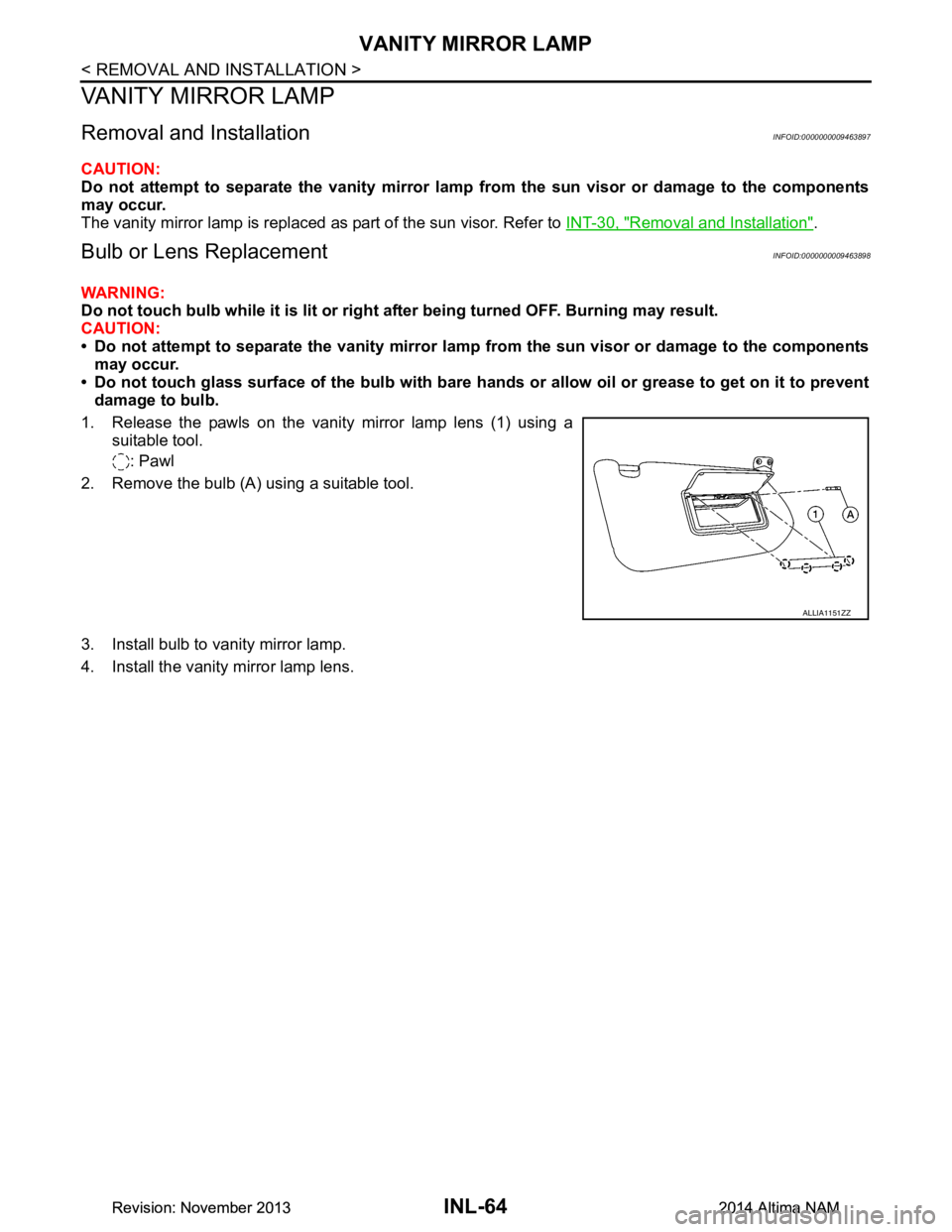
1. Release the pawls on the vanity mirror lamp lens (1) using a suitable tool.
: Pawl
2. Remove the bulb (A) using a suitable tool.
3. Install bulb to vanity mirror lamp.
4. Install the vanity mirror lamp lens.
ALLIA1151ZZ
Revision: November 20132014 Altima NAMRevision: November 20132014 Altima NAM
Page 2886 of 4801
GLOVE BOX LAMPINL-65
< REMOVAL AND INSTALLATION >
C
D E
F
G H
I
J
K
M A
B
INL
N
O P
GLOVE BOX LAMP
Removal and InstallationINFOID:0000000009463899
WARNING:
Do not touch bulb while it is lit or right after being turned OFF. Burning may result.
CAUTION:
Do not touch glass surface of the bulb with bare hands or allow oil or grease to get on it to prevent
damage to bulb.
REMOVAL
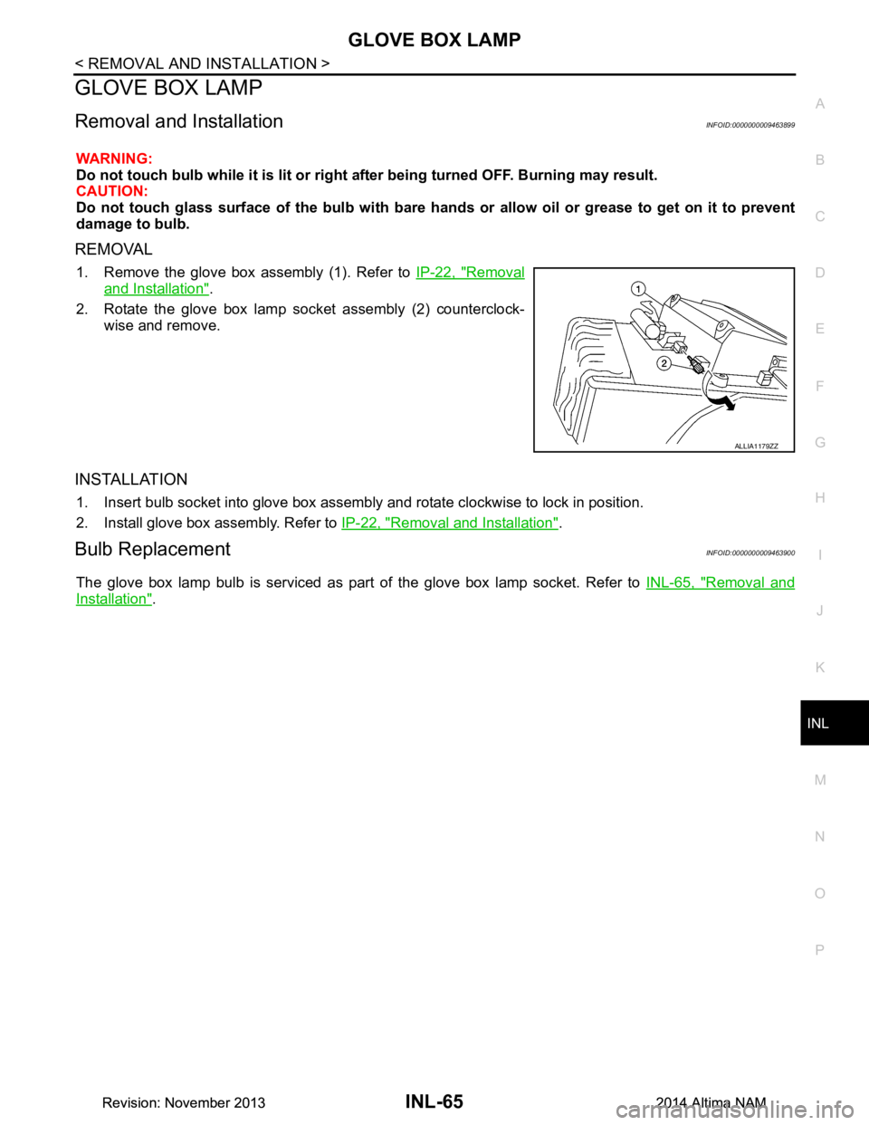
1. Remove the glove box assembly (1). Refer to IP-22, "Removal
and Installation".
2. Rotate the glove box lamp socket assembly (2) counterclock- wise and remove.
INSTALLATION
1. Insert bulb socket into glove box assembly and rotate clockwise to lock in position.
2. Install glove box assembly. Refer to IP-22, "Removal and Installation"
.
Bulb ReplacementINFOID:0000000009463900
The glove box lamp bulb is serviced as part of the glove box lamp socket. Refer to INL-65, "Removal and
Installation".
ALLIA1179ZZ
Revision: November 20132014 Altima NAMRevision: November 20132014 Altima NAM
Page 2887 of 4801
INL-66
< REMOVAL AND INSTALLATION >
STEP LAMP
STEP LAMP
Bulb or Lens ReplacementINFOID:0000000009463901
WARNING:
Do not touch bulb while it is lit or right after being turned OFF. Burning may result.
CAUTION:
Do not touch glass surface of the bulb with bare ha nds or allow oil or grease to get on it to prevent
damage to bulb.
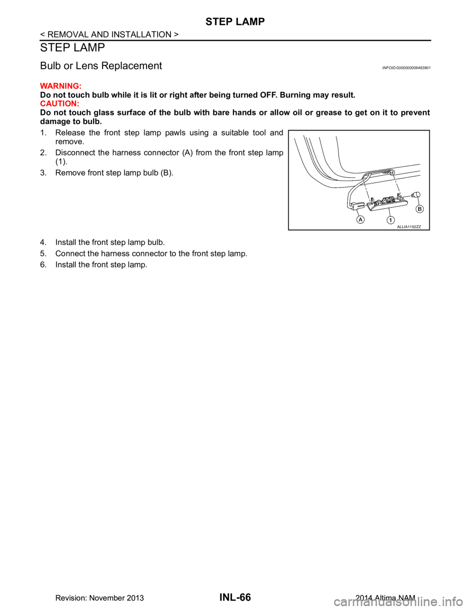
1. Release the front step lamp pawls using a suitable tool and remove.
2. Disconnect the harness connector (A) from the front step lamp (1).
3. Remove front step lamp bulb (B).
4. Install the front step lamp bulb.
5. Connect the harness connector to the front step lamp.
6. Install the front step lamp.
ALLIA1152ZZ
Revision: November 20132014 Altima NAMRevision: November 20132014 Altima NAM
Page 2888 of 4801
PERSONAL LAMPINL-67
< REMOVAL AND INSTALLATION >
C
D E
F
G H
I
J
K
M A
B
INL
N
O P
PERSONAL LAMP
Removal and InstallationINFOID:0000000009463902
CAUTION:
Do not attempt to separate the personal lamp rear from the headlining or damage to the components
may occur.
The personal lamp rear is replaced as part of the headlining. Refer to INT-30, "Removal and Installation"
.
Bulb or Lens ReplacementINFOID:0000000009463903
WARNING:
Do not touch bulb while it is lit or right after being turned OFF. Burning may result.
CAUTION:
Do not touch glass surface of the bulb with bare hands or allow oil or grease to get on it to prevent
damage to bulb.
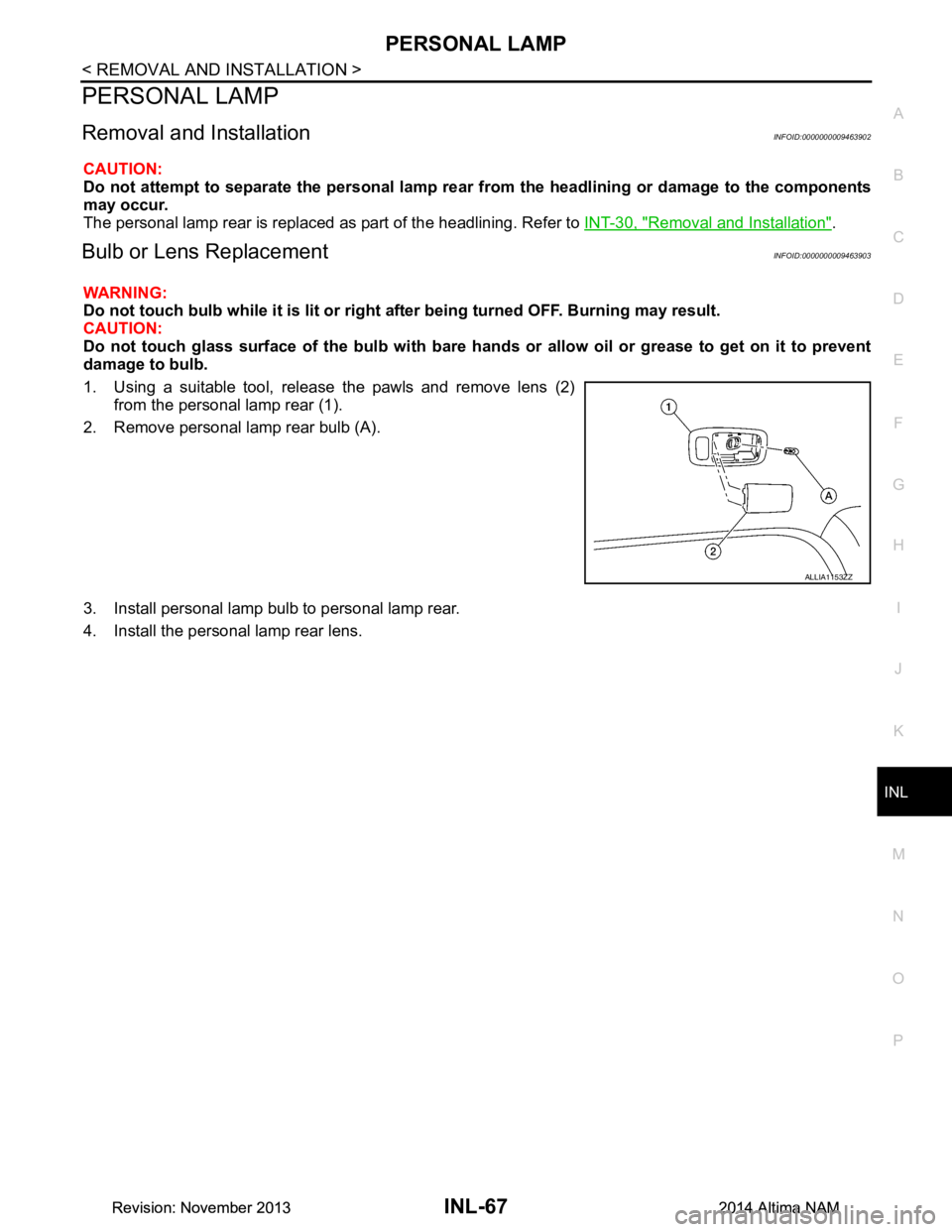
1. Using a suitable tool, release the pawls and remove lens (2) from the personal lamp rear (1).
2. Remove personal lamp rear bulb (A).
3. Install personal lamp bulb to personal lamp rear.
4. Install the personal lamp rear lens.
ALLIA1153ZZ
Revision: November 20132014 Altima NAMRevision: November 20132014 Altima NAM
Page 2889 of 4801
INL-68
< REMOVAL AND INSTALLATION >
TRUNK ROOM LAMP
TRUNK ROOM LAMP
Removal and InstallationINFOID:0000000009463904
WARNING:
Do not touch bulb while it is lit or right after being turned OFF. Burning may result.
CAUTION:
Do not touch glass surface of the bulb with bare ha nds or allow oil or grease to get on it to prevent
damage to bulb.
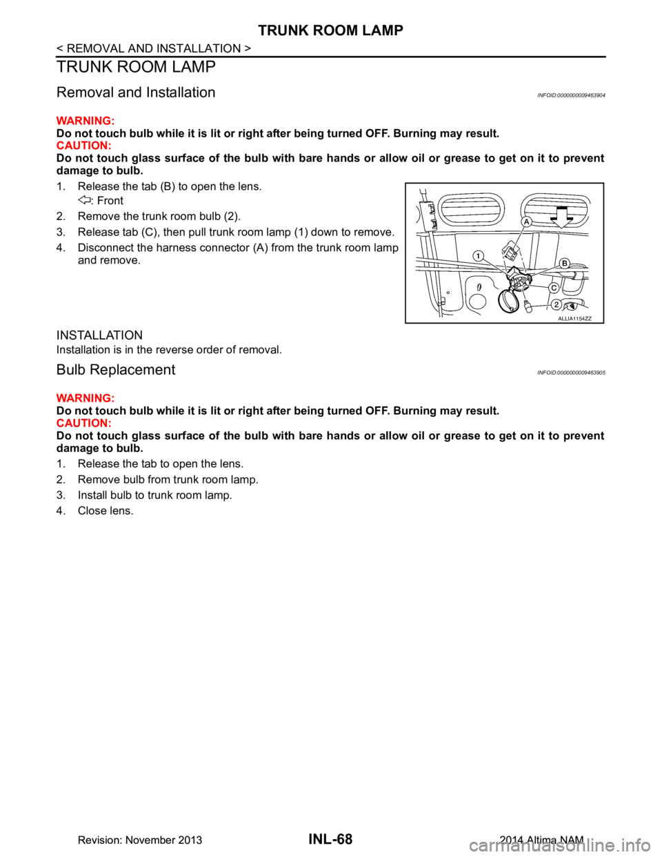
1. Release the tab (B) to open the lens. : Front
2. Remove the trunk room bulb (2).
3. Release tab (C), then pull trunk room lamp (1) down to remove.
4. Disconnect the harness connector (A ) from the trunk room lamp
and remove.
INSTALLATION
Installation is in the reverse order of removal.
Bulb ReplacementINFOID:0000000009463905
WARNING:
Do not touch bulb while it is lit or right after being turned OFF. Burning may result.
CAUTION:
Do not touch glass surface of the bulb with bare ha nds or allow oil or grease to get on it to prevent
damage to bulb.
1. Release the tab to open the lens.
2. Remove bulb from trunk room lamp.
3. Install bulb to trunk room lamp.
4. Close lens.
ALLIA1154ZZ
Revision: November 20132014 Altima NAMRevision: November 20132014 Altima NAM