2014 MITSUBISHI OUTLANDER SPORT set clock
[x] Cancel search: set clockPage 23 of 388
Installation of accessories2-14 General information
2
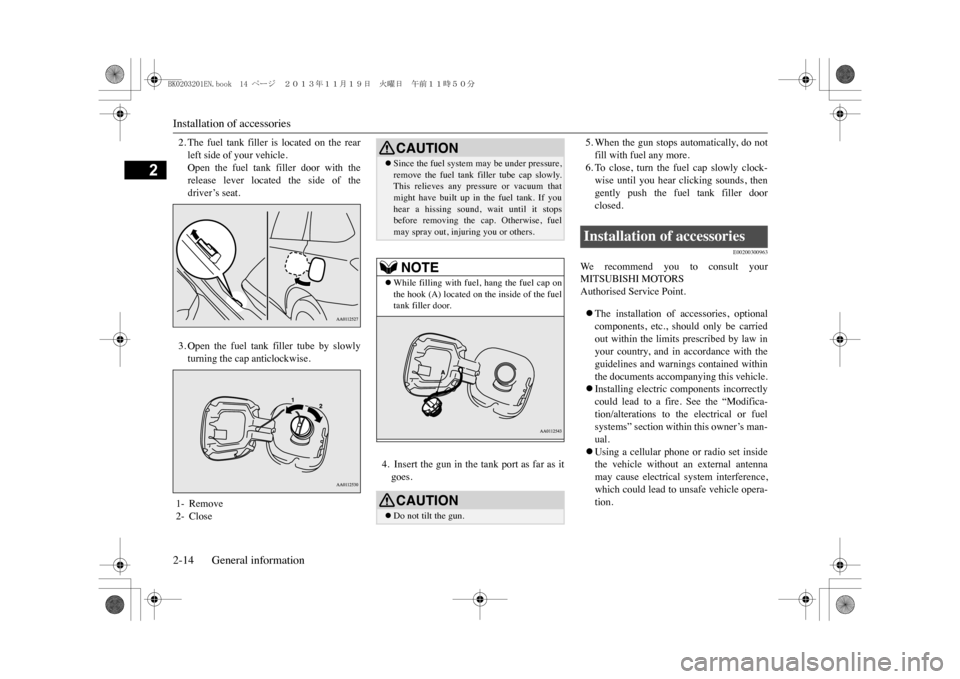
2. The fuel tank filler is located on the rearleft side of your vehicle.Open the fuel tank filler door with therelease lever located the side of thedriver’s seat.3. Open the fuel tank filler tube by slowlyturning the cap anticlockwise.
4. Insert the gun in the tank port as far as itgoes.
5. When the gun stops automatically, do notfill with fuel any more.6. To close, turn the fuel cap slowly clock-wise until you hear clicking sounds, thengently push the fuel tank filler doorclosed.
E00200300963
We r e c o m m e n d y o u t o c o n s u l t y o u rMITSUBISHI MOTORSAuthorised Service Point.�zThe installation of accessories, optionalcomponents, etc., should only be carriedout within the limits prescribed by law inyour country, and in accordance with theguidelines and warnings contained withinthe documents accompanying this vehicle.�zInstalling electric components incorrectlycould lead to a fire. See the “Modifica-tion/alterations to the electrical or fuelsystems” section within this owner’s man-ual.�zUsing a cellular phone or radio set insidethe vehicle without an external antennamay cause electrical system interference,which could lead to unsafe vehicle opera-tion.
1- Remove2- Close
CAUTION�zSince the fuel system
may be under pressure,
remove the fuel tank filler tube cap slowly.This relieves any pressure or vacuum thatmight have built up in the fuel tank. If youhear a hissing sound, wait until it stopsbefore removing the cap. Otherwise, fuelmay spray out, injuring you or others.NOTE
�zWhile filling with fuel, hang the fuel cap onthe hook (A) located on the inside of the fueltank filler door.CAUTION�zDo not tilt the gun.
Installation of accessories
BK0203201EN.book 14 ページ 2013年11月19日 火曜日 午前11時50分
Page 55 of 388
Keyless operation system4-10 Locking and unlocking
4
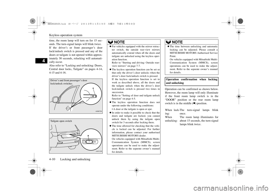
time, the room lamp will turn on for 15 sec-onds. The turn-signal lamps will blink twice.If the driver’s or front passenger’s doorlock/unlock switch is pressed and any of thedoors or tailgate is not opened within approx-imately 30 seconds, relocking will automati-cally occur.Also refer to “Locking and unlocking: Doors,Central door locks, Tailgate” on pages 4-14,4-15 and 4-16.
Operation can be confirmed as shown below.However, the room lamp will only illuminateif the front room lamp switch is in the“DOOR” position or the rear room lampswitch is in the middle (
�z) position.
Driver’s and front passenger’s door lock/unlock switchesTa i l g a t e o p e n s w i t c h
NOTE
�zFor vehicles equipped wi
th the mirror retrac-
tor switch, the outside rear-view mirrorsautomatically extend when all the doors andtailgate are unlocked us
ing the keyless oper-
ation function.Refer to “Starting and driving: Outside rear-view mirrors” on page 7-7.�zThe keyless operation f
unction can be set so
that only the driver’s door unlocks when thedriver’s door lock/unlock switch is pressed.If the keyless operati
on function is set to
work as described above, all the doors andthe tailgate unlock when the driver’s doorlock/unlock switch is pressed two times insuccession.Refer to “Setting of door and tailgate unlockfunction” on page 4-5.�zThe keyless operation function does notoperate under the following conditions:•A door or the tailgate is open or ajar.�zIn order to make it possible to check that thedoors and tailgate are locked, you cannotunlock them by using the tailgate openswitch for 3 seconds after locking them.�zThe time allowed for checking that the vehi-cle is locked can be adjusted. For furtherinformation, please contact your authorisedMITSUBISHI MOTORS dealer.On vehicles equipped
with Mitsubishi Multi-
Communication System (MMCS), screenoperations can be used to make the adjust-ment. Refer to the se
parate owner’s manual
for details.
�zThe time between unlocking and automaticlocking can be adjusted. Please consult aMITSUBISHI MOTORS Authorised ServicePoint.On vehicles equipped with Mitsubishi Multi-Communication System (MMCS), screenoperations can be used to make the adjust-ment. Refer to the separate owner’s manualfor details.
Operation confirmation when lockingand unlockingWhen lock-ing:
The turn-signal lamps blinkonce.
Whenunlocking:
The room lamp illuminates forabout 15 seconds, the turn-signallamps blink twice.
NOTE
BK0203201EN.book 10 ページ 2013年11月19日 火曜日 午前11時50分
Page 259 of 388
Operation Keys8-22 For pleasant driving
8
E00737100023E00737200024
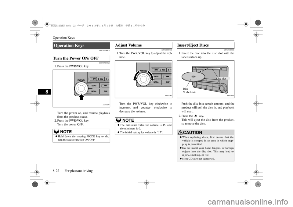
1. Press the PWR/VOL key.Turn the power on, and resume playbackfrom the previous status.2. Press the PWR/VOL key.Turn the power OFF.
E00737300025
1. Turn the PWR/VOL key to adjust the vol-ume.Turn the PWR/VOL key clockwise toincrease, and counter- clockwise todecrease the volume.
E00737400026
1. Insert the disc into the disc slot with thelabel surface up.Push the disc in a certain amount, and theproduct will pull the disc in, and playbackwill start.2. Press the key.This will eject the disc from the product,so remove the disc.
Operation Keys Tu r n t h e P o w e r O N / O F F
NOTE
�zHold down the steering MODE key to alsoturn the audio
function ON/OFF.
Adjust Volume
NOTE
�zThe maximum value for volume is 45, andthe minimum is 0.�zThe initial setting for volume is “17”.
Insert/Eject Discs
CAUTION�zWhen replacing discs, first ensure that thevehicle is stopped in an area in which stop-ping is permitted.�zDo not insert your hand, fingers, or foreignobjects into the disc slot. This may lead toinjury, smoking, or fire.�z8 cm CDs are not supported.
Disc slot
Disc*Label side
BK0203201EN.book 22 ページ 2013年11月19日 火曜日 午前11時50分
Page 262 of 388
Listen to Radio
For pleasant driving 8-25
8
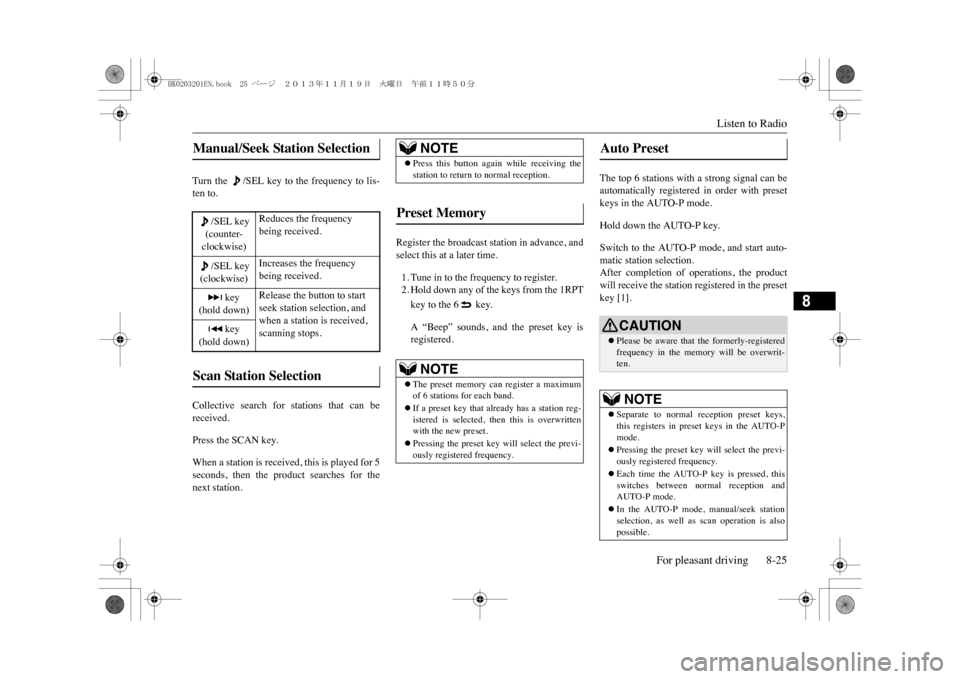
Turn the /SEL key to the frequency to lis-ten to.Collective search for stations that can bereceived.Press the SCAN key.When a station is received, this is played for 5seconds, then the product searches for thenext station.
Register the broadcast station in advance, andselect this at a later time.1. Tune in to the frequency to register.2. Hold down any of the keys from the 1RPTkey to the 6 key.A “Beep” sounds, and the preset key isregistered.
The top 6 stations with a strong signal can beautomatically registered in order with presetkeys in the AUTO-P mode.Hold down the AUTO-P key.Switch to the AUTO-P mode, and start auto-matic station selection.After completion of operations, the productwill receive the station registered in the presetkey [1].
Manual/Seek Station Selection
/SEL key(counter-clockwise)
Reduces the frequency being received.
/SEL key(clockwise)
Increases the frequency being received.
key
(hold down)
Release the button to start seek station selection, and when a station is received, scanning stops.
key
(hold down)Scan Station Selection
NOTE
�zPress this button again while receiving thestation to return to normal reception.
Preset Memory
NOTE
�zThe preset memory can register a maximumof 6 stations for each band.�zIf a preset key that al
ready has a station reg-
istered is selected, then this is overwrittenwith the new preset.�zPressing the preset key will select the previ-ously registered frequency.
Auto Preset
CAUTION�zPlease be aware that the formerly-registeredfrequency in the memory will be overwrit-ten.NOTE
�zSeparate to normal re
ception preset keys,
this registers in preset keys in the AUTO-Pmode.�zPressing the preset key will select the previ-ously registered frequency.�zEach time the AUTO-P key is pressed, thisswitches between normal reception andAUTO-P mode.�zIn the AUTO-P mode, manual/seek stationselection, as well as scan operation is alsopossible.
BK0203201EN.book 25 ページ 2013年11月19日 火曜日 午前11時50分
Page 273 of 388
System Settings8-36 For pleasant driving
8
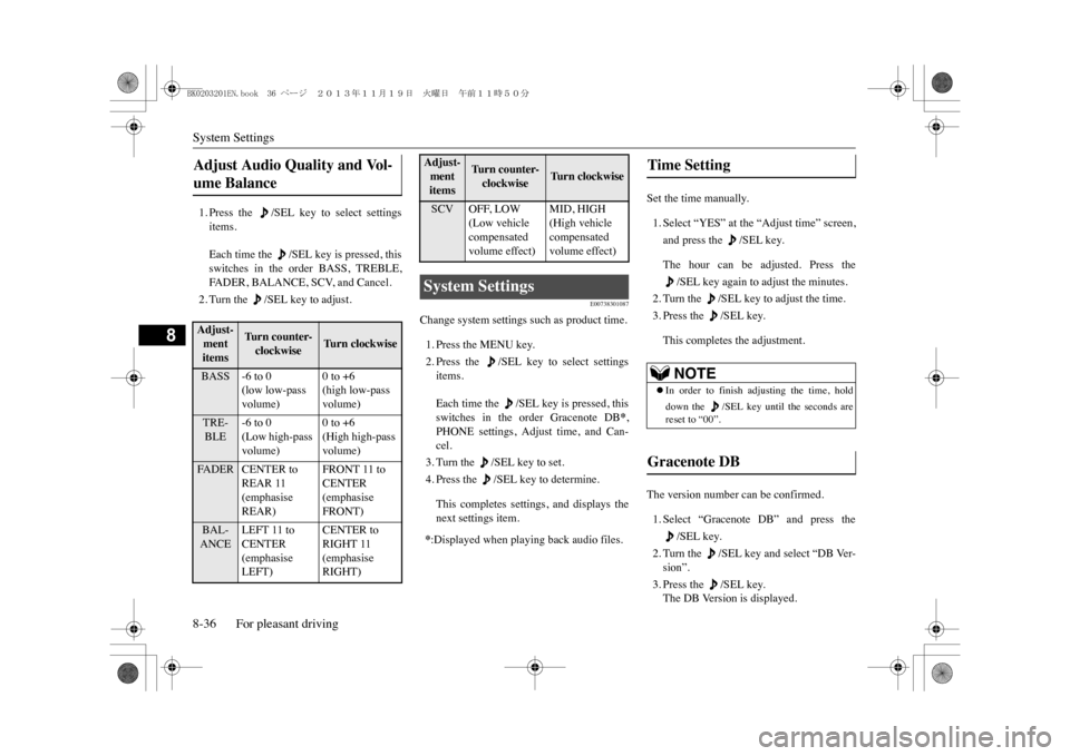
1. Press the /SEL key to select settingsitems.Each time the /SEL key is pressed, thisswitches in the order BASS, TREBLE,FA D E R , B A L A N C E , S C V, a n d C a n c e l .2. Turn the /SEL key to adjust.
E00738301087
Change system settings such as product time.1. Press the MENU key.2. Press the /SEL key to select settingsitems.Each time the /SEL key is pressed, thisswitches in the order Gracenote DB
*,
PHONE settings, Adjust time, and Can-cel.3. Turn the /SEL key to set.4. Press the /SEL key to determine.This completes settings, and displays thenext settings item.
Set the time manually.1. Select “YES” at the “Adjust time” screen,and press the /SEL key.The hour can be adjusted. Press the
/SEL key again to adjust the minutes.
2. Turn the /SEL key to adjust the time.3. Press the /SEL key.This completes the adjustment.
The version number can be confirmed.1. Select “Gracenote DB” and press the
/SEL key.
2. Turn the /SEL key and select “DB Ver-sion”.3. Press the /SEL key.The DB Version is displayed.
Adjust Audio Quality and Vol-ume Balance Adjust-ment items
Turn counter-clockwise
Tu r n c l o c k w i s e
BASS -6 to 0
(low low-pass volume)
0 to +6(high low-pass volume)
TRE-BLE
-6 to 0(Low high-pass volume)
0 to +6(High high-pass volume)
FA D E R C E N T E R t o
REAR 11 (emphasise REAR)
FRONT 11 to CENTER (emphasise FRONT)
BAL-ANCE
LEFT 11 to CENTER (emphasise LEFT)
CENTER to RIGHT 11 (emphasise RIGHT)
SCV OFF, LOW
(Low vehicle compensated volume effect)
MID, HIGH(High vehicle compensated volume effect)
System Settings *:Displayed when playing back audio files.Adjust-ment items
Tu r n c o u n t e r -clockwise
Tu r n c l o c k w i s e
Time Setting
NOTE
�zIn order to finish adjusting the time, holddown the /SEL key un
til the seconds are
reset to “00”.
Gracenote DB
BK0203201EN.book 36 ページ 2013年11月19日 火曜日 午前11時50分
Page 328 of 388
![MITSUBISHI OUTLANDER SPORT 2014 3.G Owners Manual How to change a tyre
For emergencies 9-17
9
7. Turn the wheel nuts clockwise by hand toinitially tighten them.[Type 1: On vehicles with steel wheels]Te m p o r a r i l y t i g h t e n t h e w h MITSUBISHI OUTLANDER SPORT 2014 3.G Owners Manual How to change a tyre
For emergencies 9-17
9
7. Turn the wheel nuts clockwise by hand toinitially tighten them.[Type 1: On vehicles with steel wheels]Te m p o r a r i l y t i g h t e n t h e w h](/manual-img/19/7545/w960_7545-327.png)
How to change a tyre
For emergencies 9-17
9
7. Turn the wheel nuts clockwise by hand toinitially tighten them.[Type 1: On vehicles with steel wheels]Te m p o r a r i l y t i g h t e n t h e w h e e l n u t s b yhand until the tapered parts of the wheelnuts make light contact with the seats ofthe wheel holes and the wheel is notloose.[Type 2: On vehicles with aluminiumwheels]Te m p o r a r i l y t i g h t e n t h e w h e e l n u t s b yhand until the flange parts of the wheelnuts make light contact with the wheeland the wheel is not loose.
8. Lower the vehicle slowly by rotating thewheel nut wrench anticlockwise until thetyre touches the ground.
9. Tighten the nuts in the order shown in theillustration until each nut has been tight-ened to the torque listed here.Tightening torque 88 to 108 N•m
10. On vehicles with wheel covers, install the
covers (refer to “Wheel covers” on page9-18).
11. Lower and remove the jack, then store the
jack, flat tyre, and chocks. Have yourdamaged tyre repaired as soon as possi-ble.
CAUTION�zNever apply oil to either the wheel bolts orthe nuts or they will tighten too much.
Ty p e 1Ty p e 2
NOTE
�zOn vehicles with aluminium wheels, if all 4aluminium wheels are changed to steelwheels. e. g. when fitting winter tyres, usetapered nuts.
CAUTION�zNever use your foot or
a pipe extension for
extra force in the wheel nut wrench. If youdo so, you will tighten the nut too much.
BK0203201EN.book 17 ページ 2013年11月19日 火曜日 午前11時50分
Page 383 of 388
Alphabetical index13-2
13
D
Daytime running lamps
Bulb capacity
...............................
11-22
Demister (rear window)
.......................
6-53
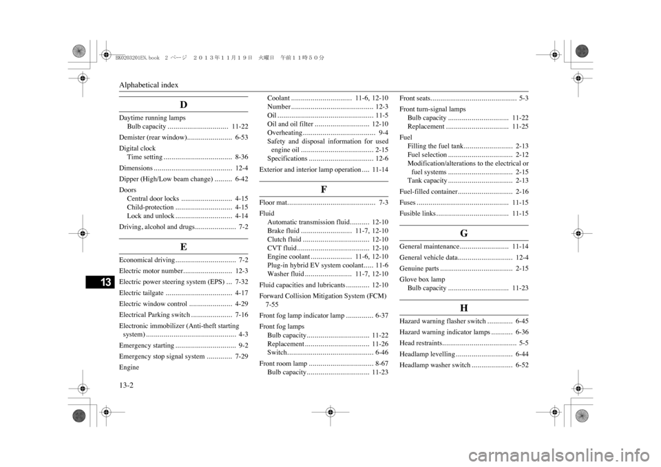
Digital clock
Time setting
...................................
8-36
Dimensions
........................................
12-4
Dipper (High/Low beam change)
.........
6-42
Doors
Central door locks
..........................
4-15
Child-protection
.............................
4-15
Lock and unlock
.............................
4-14
Driving, alcohol and drugs
.....................
7-2
E
Economical driving
...............................
7-2
Electric motor number
.........................
12-3
Electric power steering system (EPS)
...
7-32
Electric tailgate
..................................
4-17
Electric window control
......................
4-29
Electrical Parking switch
.....................
7-16
Electronic immobilizer (Anti-theft starting system)
..............................................
4-3
Emergency starting
...............................
9-2
Emergency stop signal system
.............
7-29
Engine
Coolant
...............................
11-6
, 12-10
Number
..........................................
12-3
Oil
.................................................
11-5
Oil and oil filter
............................
12-10
Overheating
.....................................
9-4
Safety and disposal information for usedengine oil
.....................................
2-15
Specifications
.................................
12-6
Exterior and interior lamp operation
....
11-14
F
Floor mat
.............................................
7-3
Fluid
Automatic transmission fluid
..........
12-10
Brake fluid
..........................
11-7
, 12-10
Clutch fluid
..................................
12-10
CVT fluid
.....................................
12-10
Engine coolant
.....................
11-6
, 12-10
Plug-in hybrid EV system coolant
.....
11-6
Washer fluid
........................
11-7
, 12-10
Fluid capacities and lubricants
............
12-10
Forward Collision Mitigation System (FCM)7-55Front fog lamp indicator lamp
..............
6-37
Front fog lamps
Bulb capacity
................................
11-22
Replacement
.................................
11-26
Switch
............................................
6-46
Front room lamp
.................................
8-67
Bulb capacity
................................
11-23
Front seats
............................................
5-3
Front turn-signal lamps
Bulb capacity
...............................
11-22
Replacement
................................
11-25
Fuel
Filling the fuel tank
.........................
2-13
Fuel selection
.................................
2-12
Modification/alterations to the electrical orfuel systems
.................................
2-15
Tank capacity
.................................
2-13
Fuel-filled container
............................
2-16
Fuses
...............................................
11-15
Fusible links
.....................................
11-15
G
General maintenance
.........................
11-14
General vehicle data
............................
12-4
Genuine parts
.....................................
2-15
Glove box lamp
Bulb capacity
...............................
11-23
H
Hazard warning flasher switch
.............
6-45
Hazard warning indicator lamps
...........
6-36
Head restraints
......................................
5-5
Headlamp levelling
.............................
6-44
Headlamp washer switch
.....................
6-52
BK0203201EN.book 2 ページ 2013年11月19日 火曜日 午前11時50分