Page 1853 of 2453
LU(H6DO)-4
General Description
LUBRICATION
C: CAUTION
•Wear work clothing, including a cap, protective goggles and protective shoes during operation.
•Remove contamination including dirt and corrosion before removal, installation or disassembly.
•Keep the disassembled parts in order and protect them from dust and dirt.
•Before removal, installation or disassembly, be sure to clarify the failure. Avoid unnecessary removal, in-
stallation, disassembly and replacement.
•Be careful not to burn yourself, because each part on the vehicle is hot after running.
•Be sure to tighten fasteners including bolts and nuts to the specified torque.
•Place shop jacks or rigid racks at the specified points.
•Before disconnecting connectors of sensors or units, be sure to disconnect the ground cable from battery.
D: PREPARATION TOOL
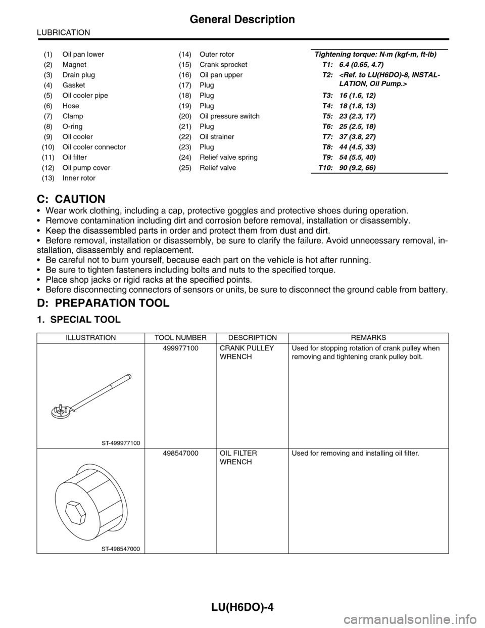
1. SPECIAL TOOL
(1) Oil pan lower (14) Outer rotorTightening torque: N·m (kgf-m, ft-lb)
(2) Magnet (15) Crank sprocketT1: 6.4 (0.65, 4.7)
(3) Drain plug (16) Oil pan upperT2:
LATION, Oil Pump.>(4) Gasket (17) Plug
(5) Oil cooler pipe (18) PlugT3: 16 (1.6, 12)
(6) Hose (19) PlugT4: 18 (1.8, 13)
(7) Clamp (20) Oil pressure switchT5: 23 (2.3, 17)
(8) O-ring (21) PlugT6: 25 (2.5, 18)
(9) Oil cooler (22) Oil strainerT7: 37 (3.8, 27)
(10) Oil cooler connector (23) PlugT8: 44 (4.5, 33)
(11) Oil filter (24) Relief valve springT9: 54 (5.5, 40)
(12) Oil pump cover (25) Relief valveT10: 90 (9.2, 66)
(13) Inner rotor
ILLUSTRATION TOOL NUMBER DESCRIPTION REMARKS
499977100 CRANK PULLEY
WRENCH
Used for stopping rotation of crank pulley when
removing and tightening crank pulley bolt.
498547000 OIL FILTER
WRENCH
Used for removing and installing oil filter.
ST-499977100
ST-498547000
Page 1855 of 2453
LU(H6DO)-6
Oil Pressure System
LUBRICATION
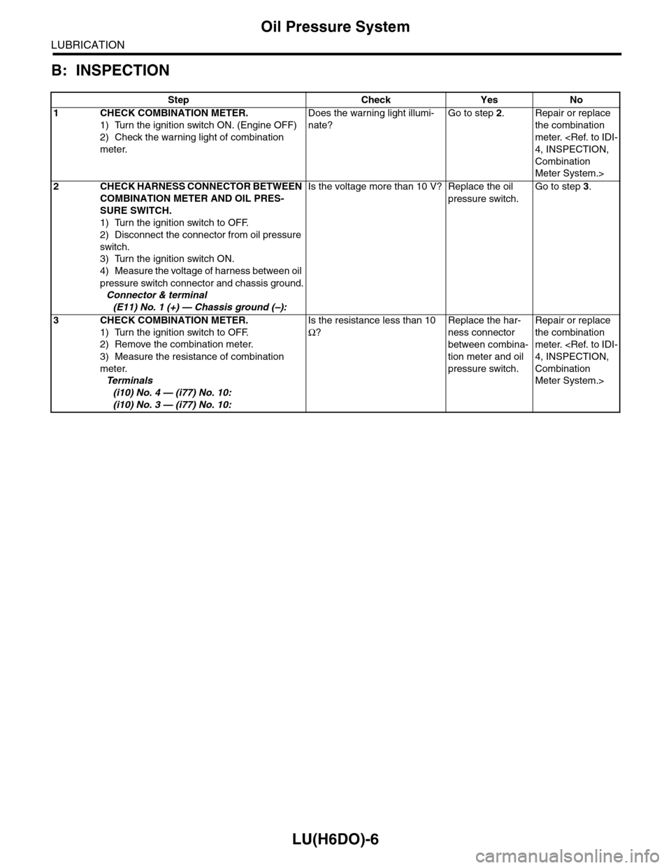
B: INSPECTION
Step Check Yes No
1CHECK COMBINATION METER.
1) Turn the ignition switch ON. (Engine OFF)
2) Check the warning light of combination
meter.
Does the warning light illumi-
nate?
Go to step 2.Repair or replace
the combination
meter.
4, INSPECTION,
Combination
Meter System.>
2CHECK HARNESS CONNECTOR BETWEEN
COMBINATION METER AND OIL PRES-
SURE SWITCH.
1) Turn the ignition switch to OFF.
2) Disconnect the connector from oil pressure
switch.
3) Turn the ignition switch ON.
4) Measure the voltage of harness between oil
pressure switch connector and chassis ground.
Connector & terminal
(E11) No. 1 (+) — Chassis ground (–):
Is the voltage more than 10 V? Replace the oil
pressure switch.
Go to step 3.
3CHECK COMBINATION METER.
1) Turn the ignition switch to OFF.
2) Remove the combination meter.
3) Measure the resistance of combination
meter.
Te r m i n a l s
(i10) No. 4 — (i77) No. 10:
(i10) No. 3 — (i77) No. 10:
Is the resistance less than 10
Ω?
Replace the har-
ness connector
between combina-
tion meter and oil
pressure switch.
Repair or replace
the combination
meter.
4, INSPECTION,
Combination
Meter System.>
Page 1864 of 2453
LU(H6DO)-15
Oil Cooler
LUBRICATION
9. Oil Cooler
A: REMOVAL
1) Lift-up the vehicle.
2) Remove the under cover.
3) Drain engine coolant.
COOLANT, REPLACEMENT, Engine Coolant.>
4) Drain the engine oil.
PLACEMENT, Engine Oil.>
5) Remove the bolts which hold the water pipe to
engine.
6) Disconnect the water hose from oil cooler.
7) Remove the oil filter using the ST.
LU(H6DO)-14, REMOVAL, Engine Oil Filter.>
ST 498547000 OIL FILTER WRENCH
NOTE:
Set a container under the vehicle.
8) Remove the oil cooler connector and remove oil
cooler.
B: INSTALLATION
1) Install the oil cooler to oil pan upper with oil cool-
er connector.
Tightening torque:
T: 54 N·m (5.5 kgf-m, 40 ft-lb)
NOTE:
Use new O-rings.
2) Install the oil filter.
STALLATION, Engine Oil Filter.>
LU-00132
LU-00133
LU-00134
(A) Oil cooler connector
(B) Oil cooler
(C) O-ring
(A) Oil cooler connector
(B) Oil cooler
(C) O-ring
(A)
(B)(C)
LU-00135
(A)
(B)(C)
T
LU-00136
LU-00134
Page 1878 of 2453
ME(H6DO)-12
General Description
MECHANICAL
(1) Cylinder block (RH) (13) ClampTightening torque: N·m (kgf-m, ft-lb)
(2) Cylinder block (LH) (14) HoseT1: 6.4 (0.65, 4.7)
(3) Rear oil seal (15) Oil cooler pipeT2: 18 (1.8, 13.3)
(4) Service hole cover (16) Oil coolerT3: 25 (2.5, 18)
(5) O-ring (17) ConnectorT4: 16 (1.6, 12)
(6) Oil pan upper (18) Oil filterT5: 37 (3.8, 27)
(7) Oil pressure switch (19) PlugT6: 44 (4.5, 33)
(8) Oil strainer (20) Crankshaft position sensor holderT7: 54 (5.5, 40)
(9) Magnet (21) Relief valveT8: 70 (7.1, 52)
(10) Oil pan lower (22) Relief valve springT9: 23 (2.3, 17)
(11) Metal gasket (23) PlugT10: 90 (9.2, 67)
(12) Drain plug
Page 1880 of 2453
ME(H6DO)-14
General Description
MECHANICAL
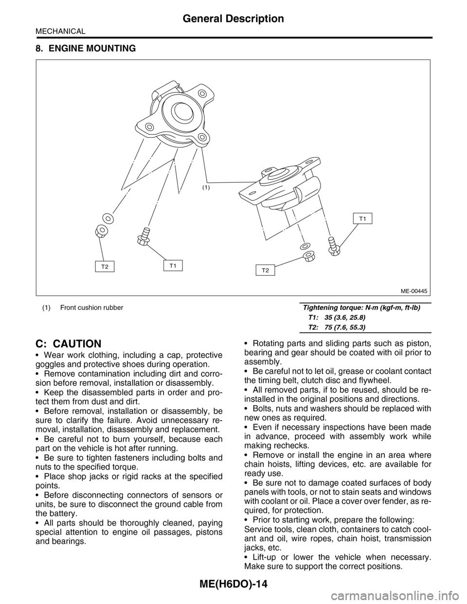
8. ENGINE MOUNTING
C: CAUTION
•Wear work clothing, including a cap, protective
goggles and protective shoes during operation.
•Remove contamination including dirt and corro-
sion before removal, installation or disassembly.
•Keep the disassembled parts in order and pro-
tect them from dust and dirt.
•Before removal, installation or disassembly, be
sure to clarify the failure. Avoid unnecessary re-
moval, installation, disassembly and replacement.
•Be careful not to burn yourself, because each
part on the vehicle is hot after running.
•Be sure to tighten fasteners including bolts and
nuts to the specified torque.
•Place shop jacks or rigid racks at the specified
points.
•Before disconnecting connectors of sensors or
units, be sure to disconnect the ground cable from
the battery.
•All parts should be thoroughly cleaned, paying
special attention to engine oil passages, pistons
and bearings.
•Rotating parts and sliding parts such as piston,
bearing and gear should be coated with oil prior to
assembly.
•Be careful not to let oil, grease or coolant contact
the timing belt, clutch disc and flywheel.
•All removed parts, if to be reused, should be re-
installed in the original positions and directions.
•Bolts, nuts and washers should be replaced with
new ones as required.
•Even if necessary inspections have been made
in advance, proceed with assembly work while
making rechecks.
•Remove or install the engine in an area where
chain hoists, lifting devices, etc. are available for
ready use.
•Be sure not to damage coated surfaces of body
panels with tools, or not to stain seats and windows
with coolant or oil. Place a cover over fender, as re-
quired, for protection.
•Prior to starting work, prepare the following:
Service tools, clean cloth, containers to catch cool-
ant and oil, wire ropes, chain hoist, transmission
jacks, etc.
•Lift-up or lower the vehicle when necessary.
Make sure to support the correct positions.
(1) Front cushion rubber Tightening torque: N·m (kgf-m, ft-lb)
T1: 35 (3.6, 25.8)
T2: 75 (7.6, 55.3)
(1)
T2
T1
T1T2
ME-00445
Page 1885 of 2453
ME(H6DO)-19
General Description
MECHANICAL
18482AA010 CARTRIDGE Troubleshooting for electrical system.
22771AA030 SUBARU
SELECT MONI-
TOR KIT
Tr o u b l e s h o o t i n g f o r e l e c t r i c a l s y s t e m .
18233AA000 PISTON PIN
SNAP RING PLI-
ERS
Used for removing and installing snap ring of pis-
ton pin.
498277200 STOPPER SET Used for installing automatic transmission assem-
bly to engine.
42099AE000 CONNECTOR
REMOVER
Used for disconnecting quick connector of the
engine compartment.
ILLUSTRATION TOOL NUMBER DESCRIPTION REMARKS
ST18482AA010
ST22771AA030
ST18233AA000
ST-498277200
ST42099AE000
Page 1888 of 2453
ME(H6DO)-22
Idle Speed
MECHANICAL
3. Idle Speed
A: INSPECTION
1) Before checking the idle speed, check the fol-
lowing item:
(1) Check the air cleaner element is free from
clogging, ignition timing is correct, spark plugs
are in good condition, and hoses are connected
properly.
(2) Check the malfunction indicator light does
not illuminate.
2) Idle the engine.
3) Stop the engine, and turn the ignition switch to
OFF.
4) Insert the cartridge to Subaru Select Monitor.
5) Connect the Subaru Select Monitor to data link
connector.
6) Turn the ignition switch to ON and Subaru Select
Monitor switch to ON.
7) Select {Each System Check} in Main Menu.
8) Select {Engine} in Selection Menu.
9) Select {Current Data Display & Save} in Engine
Control System Diagnosis.
10) Select {Data Display} in Data Display Menu.
11) Start the engine, and read the engine idle
speed.
12) Check the idle speed when no-loaded. (Head-
light, heater fan, rear defroster, radiator fan, A/C
and etc. are OFF)
Idle speed [No load and gears in neutral]:
650±50 rpm
13) Check the idle speed when loaded. (Turn the A/
C switch to “ON” and operate the compressor for at
least one minute before measurement.)
Idle speed [A/C ON and gears in neutral]:
770±50 rpm
NOTE:
Idle speed cannot be adjusted manually, because
the idle speed is automatically adjusted. If the pre-
scribed idle speed cannot be maintained, refer to
General On-board Diagnosis Table under “Engine
Control System”.
sic Diagnostic Procedure.>
Page 1889 of 2453
ME(H6DO)-23
Ignition Timing
MECHANICAL
4. Ignition Timing
A: INSPECTION
CAUTION:
After warming-up, engine becomes very hot. Be
careful not to burn yourself at measurement.
1) Before checking the ignition timing, check the
following item:
(1) Check the air cleaner element is free from
clogging, spark plugs are in good condition, and
hoses are connected properly.
(2) Check the malfunction indicator light does
not illuminate.
2) Idle the engine.
3) Stop the engine, and turn the ignition switch to
OFF.
4) Insert the cartridge to Subaru Select Monitor.
5) Connect the Subaru Select Monitor to data link
connector.
6) Turn the ignition switch to ON and Subaru Select
Monitor switch to ON.
7) Select {Each System Check} in Main Menu.
8) Select {Engine} in Selection Menu.
9) Select {Current Data Display & Save} in Engine
Control System Diagnosis.
10) Select {Data Display} in Data Display Menu.
11) Start the engine and check the ignition timing at
idle speed.
Ignition timing [BTDC/rpm]:
15°±8°/650
If the timing is not correct, check the ignition control
system. Refer to Engine Control System.
EN(H6DO)(diag)-2, Basic Diagnostic Procedure.>